The document discusses analysis of protection systems using the DigSILENT PowerFactory software tool. It covers topics such as objectives of protection systems, types of abnormalities in power systems, criteria for fault detection, current transformers and potential transformers, and overcurrent protection including time-current characteristics. The analysis of protection systems aims to prevent injuries, minimize equipment damage, and limit service interruptions during faults or abnormal conditions on power grids.


![Dr. Francisco M. Gonzalez-Longatt, fglongatt@ieee.org .Copyright © 2009 14/23
All
rights
reserved.
No
part
of
this
publication
may
be
reproduced
or
distributed
in
any
form
without
permission
of
the
author.
Copyright
©
2009.
http:www.fglongatt.org.ve
Característica de tiempo definido
• Tiempo total de limpieza de
falla (Tcf):
Tfc = Trelay + Tbrk
Trelay: tiempo de disparo del rele
Tbrk : Tiempo de disparo del interruptor
• Tiempo de disparo del rele
(Trelay):
Trelay = Ts + Tset
Ts: tiempo de arranque
Tset: tiempo ajustado
• Ajuste de corriente
Ajuste de corriente de
arranque
>>
> I
und
I
1000 10000 100000
[pri.A]
0.01
0.1
1
10
[s]
I>/I>>
DIgS
ILE
NT
Tfct=Trelay+Tbrk
Tfct=Trelay+Tbrk
I>>
I>](https://image.slidesharecdn.com/sistemasproteccion-220729165541-236ba87d/85/Sistemas_Proteccion-pdf-14-320.jpg)
![Dr. Francisco M. Gonzalez-Longatt, fglongatt@ieee.org .Copyright © 2009 15/23
All
rights
reserved.
No
part
of
this
publication
may
be
reproduced
or
distributed
in
any
form
without
permission
of
the
author.
Copyright
©
2009.
http:www.fglongatt.org.ve
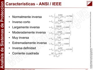
Característica de tiempo inverso
• Tiempo total de limpieza de
falla (Tcf):
Tfc = Trelay + Tbrk
Trelay: tiempo de disparo del rele
Tbrk : Tiempo de disparo del interruptor
• Tiempo de disparo del rele
(Trelay):
Trelay = Ts + Tset
Ts: tiempo de arranque
Tset: tiempo ajustado
• Ajuste de corriente
Ipset: rango de corriente ajustada
Imin: Corriente de arranque
1000 10000 100000
[pri.A]
0.01
0.1
1
10
[s]
AMZ
DIgSILENT
Tpset
Ipset
Tfct=Trelay+Tbrk
Imin](https://image.slidesharecdn.com/sistemasproteccion-220729165541-236ba87d/85/Sistemas_Proteccion-pdf-15-320.jpg)


![Dr. Francisco M. Gonzalez-Longatt, fglongatt@ieee.org .Copyright © 2009 21/23
All
rights
reserved.
No
part
of
this
publication
may
be
reproduced
or
distributed
in
any
form
without
permission
of
the
author.
Copyright
©
2009.
http:www.fglongatt.org.ve
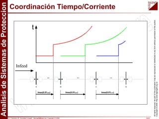
Interruptores de Bajo Voltaje
• Tiempo largo con retardo
por protección de
sobrecarga
• Tiempo corto con retardo
por cortocircuito – con o
sin característica I²t
• Protección instantánea
contra cortocircuito
1000 10000 100000
[pri.A]
0.001
0.1
10
1000
[s]
DIgSILENT
I²t on/off
Ir
Im
I
tm
tr
Tiempo largo de
retardo por
proteccion de
sobrecarga
Tiempo corto con
retardo por cortocircuito
Protección instantánea
contra cortocircuito
LV-Breaker](https://image.slidesharecdn.com/sistemasproteccion-220729165541-236ba87d/85/Sistemas_Proteccion-pdf-21-320.jpg)
![Dr. Francisco M. Gonzalez-Longatt, fglongatt@ieee.org .Copyright © 2009 22/23
All
rights
reserved.
No
part
of
this
publication
may
be
reproduced
or
distributed
in
any
form
without
permission
of
the
author.
Copyright
©
2009.
http:www.fglongatt.org.ve
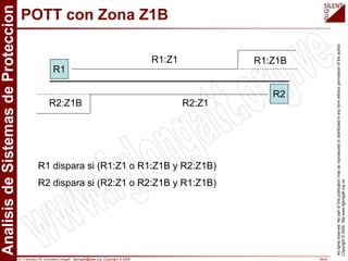
Caracteristicas de Arranque de Motores
• Característica de
arranque
Corriente nominal
Corriente de arranque
Corriente de magnetización (Inrush)
Duración de la corriente de Inrush
Limite térmico
bajo condiciones frías
bajo condiciones calientes
n
n
n
U
S
I
⋅
=
3
a
I
cold
t
hot
t
start
t
p
I
inrush
t
1000 10000
[pri.A]
0
0.1
1
10
100
[s]
Motor - 1
DIgSILENT
Ia
In
tinrush
thot
tcold
Ip
tstart](https://image.slidesharecdn.com/sistemasproteccion-220729165541-236ba87d/85/Sistemas_Proteccion-pdf-22-320.jpg)
![Dr. Francisco M. Gonzalez-Longatt, fglongatt@ieee.org .Copyright © 2009 23/23
All
rights
reserved.
No
part
of
this
publication
may
be
reproduced
or
distributed
in
any
form
without
permission
of
the
author.
Copyright
©
2009.
http:www.fglongatt.org.ve
Curva Limite de Cables
• Capabilidad térmica
Corriente de cortocircuito
Periodo nominal(1s)
Tiempo de liberación de falla
• Corriente de
magnetización
Corriente de magnetizacion
(Inrush)
Duración de la corriente de
Inrush
0.01 10
kr
th thr k
k
T
I I con s T s
T
< ≤ ≤
thr
I
kr
T
k
T
100 10000 100000
[pri.A]
0.01
0.1
1
10
[s]
Cable-1
DIgSILENT
Ithr
Tkr
Ip
tinrush
p
I
inrush
t](https://image.slidesharecdn.com/sistemasproteccion-220729165541-236ba87d/85/Sistemas_Proteccion-pdf-23-320.jpg)

![Dr. Francisco M. Gonzalez-Longatt, fglongatt@ieee.org .Copyright © 2009 25/23
All
rights
reserved.
No
part
of
this
publication
may
be
reproduced
or
distributed
in
any
form
without
permission
of
the
author.
Copyright
©
2009.
http:www.fglongatt.org.ve
Curva de Sobrecarga de Cables
• Sobrecarga (for t > 10s )
Corriente nominal en A
Corriente de prefalla en A
Tiempo de sobrecarga en s
Mínimo constante de tiempo
del cable
2
0
1
1
b
b
t
b
n t
I
e
I
I I para corta operacion
e
τ
τ
−
−
−
<
−
n
I
0
I
b
t
τ
100 1000 10000
[pri.A]
10
100
1000
10000
[s]
Cable-1
DIgSILENT
In](https://image.slidesharecdn.com/sistemasproteccion-220729165541-236ba87d/85/Sistemas_Proteccion-pdf-25-320.jpg)
![Dr. Francisco M. Gonzalez-Longatt, fglongatt@ieee.org .Copyright © 2009 26/23
All
rights
reserved.
No
part
of
this
publication
may
be
reproduced
or
distributed
in
any
form
without
permission
of
the
author.
Copyright
©
2009.
http:www.fglongatt.org.ve
Curva de Transformadores ANSI/IEEE - Cat. I/II
• Curva de limite térmico
– Categoría I (0.15 - 0.5
MVA)
– Categoría II (0.501 - 5
MVA)
• Curva de limite mecánico
– Categoría II (0.501 - 5
MVA)
• Corriente de
magnetización
Corriente de magnetización
Duración de la corriente de
magnetización
p
I
inrush
t
10 100 1000 10000
[pri.A]
0.1
1
10
100
1000
10000
[s]
Category I Category II
DIgSILENT
5 4
7
8
10
12 uk in %
Sn = 1MVA (10kV)
Sn = 0,1 MVA (10kV)
Ip
tinrush
térmica
mecánica](https://image.slidesharecdn.com/sistemasproteccion-220729165541-236ba87d/85/Sistemas_Proteccion-pdf-26-320.jpg)
![Dr. Francisco M. Gonzalez-Longatt, fglongatt@ieee.org .Copyright © 2009 27/23
All
rights
reserved.
No
part
of
this
publication
may
be
reproduced
or
distributed
in
any
form
without
permission
of
the
author.
Copyright
©
2009.
http:www.fglongatt.org.ve
Curva de Transformadores ANSI/IEEE Cat. III/IV
• Curva de limite térmico
– Categoría III (5.001 - 30
MVA)
– Categoría IV ( > 30 MVA)
• Curva de limite mecánico
– Categoría III (5.001 - 30
MVA)
– Categoría IV ( > 30 MVA)
• Curvas de cambio de fase
ANSI
100 1000 10000
[pri.A]
1
10
100
1000
10000
[s]
Category III Category IV
DIgSIL
ENT
Sn = 50MVA (110kV)
Sn = 10 MVA (110kV)
5 4
7
8
10
12
uk in % 5 4
7
8
10
12
thermal
mechanical](https://image.slidesharecdn.com/sistemasproteccion-220729165541-236ba87d/85/Sistemas_Proteccion-pdf-27-320.jpg)


![Dr. Francisco M. Gonzalez-Longatt, fglongatt@ieee.org .Copyright © 2009 47/23
All
rights
reserved.
No
part
of
this
publication
may
be
reproduced
or
distributed
in
any
form
without
permission
of
the
author.
Copyright
©
2009.
http:www.fglongatt.org.ve
Ejemplo: Digrama de Impedancia R-X
130.
120.
110.
100.
90.0
80.0
70.0
60.0
50.0
40.0
30.0
20.0
10.0
-10.0
-20.0
-30.0
-40.0
-50.0
-60.0
-70.0
-80.0
-90.0
-100...
-110. [pri.Ohm]
100.
90.0
80.0
70.0
60.0
50.0
40.0
30.0
20.0
10.0
-10.0..
-20.0
-30.0
-40.0
-50.0
-60.0
[pri.Ohm]
R1-Dist
R3-Mho-1
R3-Mho-1
Zl A 131.086 pri.Ohm 4.31 deg
Zl B 26.306 pri.Ohm 81.25 deg
Zl C 129.771 pri.Ohm 161.03 deg
Faulttype: BC
Tripping Time: 0.19 s
Zone:2
Ph-Ph 2: 0.19 s
Zone:3
Ph-Ph 3: 0.29 s
Zone:4
Ph-Ph 4: 0.44 s
R1-Dist
Zl A 141.551 pri.Ohm 17.88 deg
Zl B 60.135 pri.Ohm 82.35 deg
Zl C 140.851 pri.Ohm 147.44 deg
Faulttype: BC
Tripping Time: 0.37 s
Zone3
ZPHPH3: 0.37 s
DIgSILENT](https://image.slidesharecdn.com/sistemasproteccion-220729165541-236ba87d/85/Sistemas_Proteccion-pdf-47-320.jpg)
![Dr. Francisco M. Gonzalez-Longatt, fglongatt@ieee.org .Copyright © 2009 48/23
All
rights
reserved.
No
part
of
this
publication
may
be
reproduced
or
distributed
in
any
form
without
permission
of
the
author.
Copyright
©
2009.
http:www.fglongatt.org.ve
Ejemplo: Z-t Time-grading Diagram
105.
84.1
63.1
42.0
21.0
0.0 [pri.Ohm]
0.46
0.37
0.28
0.18
0.09
0.00
[s]
HV-UT2 SS-D3 SS-D2 SS-D1 HV-Infeed
105. 84.1 63.1 42.0 21.0 0.0
[pri.Ohm]
0.46
0.37
0.28
0.18
0.09
0.00
[s]
HV-Infeed
SS-D1
SS-D2
SS-D3
HV-UT2
x-Achse: Reaktanz Cub_2Rel-U1 Cub_2Rel-L2-1 Cub_3R1-Dist
Cub_1R2-D1 Cub_2R3-Mho-1 Cub_1R4-Mho-2 Cub_2R5-Mho-4
Cub_1R6-Mho-5 Cub_2R7-Mho-6 Cub_2R8-Dist
R4-Mho-2
Ph-Ph 3
Zone 3
R8-Dist
ZPHPH1
Zone 1
DIgSILENT](https://image.slidesharecdn.com/sistemasproteccion-220729165541-236ba87d/85/Sistemas_Proteccion-pdf-48-320.jpg)