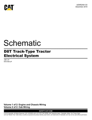
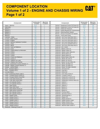
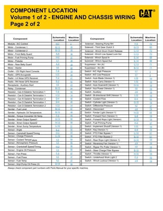
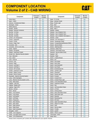
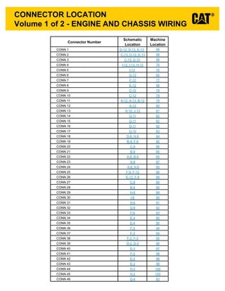
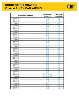
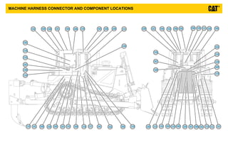
1. Click here to view the
Schematic Symbols
and Definitions page
INTERACTIVE SCHEMATIC
The Bookmarks panel will allow you to
quickly navigate to points of interest.
Click on any text that is BLUE and
underlined. These are hyperlinks
that can be used to navigate the
schematic and machine views.
When only one callout is showing on a
machine view, clicking on this button will
make all of the callouts visible. This
button is located in the top right corner
of every machine view page.
VIEW ALL CALLOUTS
Cover Page
Tables
Schematic
Machine Views
Component
Connector
Chassis View
Cab View
Engine View
Features
Options
Bookmarks X
EC-C3
EC-C2 E-C60
EC-C1
E-C61
To set your screen resolution do the following:
RIGHT CLICK on the DESKTOP.
Select PROPERTIES.
CLICK the SETTINGS TAB.
MOVE THE SLIDER under SCREEN RESOLUTION
until it shows 1024 X 768.
CLICK OK to apply the resolution.
*This document is best viewed at a
screen resolution of 1024 X 768.
*Due to different monitor sizes and PDF reader preferences
there may be some variance in linked schematic locations
FUNCTION
Zoom In
HOTKEYS (Keyboard Shortcuts)
Zoom Out
Fit to Page
Hand Tool
“CTRL” / “+”
KEYS
“CTRL” / “-”
“CTRL” / “0” (zero)
“SPACEBAR” (hold down)
Find “CTRL” / “F”
Pressure
Switch
Temperature
Switch
Level
Switch
Flow
Switch Circuit Breaker
T
ELECTRICAL SYMBOLS
Spring
(Adjustable)
Variability
Fluid
Conditioner
Pump
or Motor
BASIC HYDRAULIC
COMPONENT SYMBOLS
Click here to save a copy of
this interactive schematic
to your desktop
Search “CTRL” / “SHIFT” / “F”
2. SCHEMATIC SYMBOLS AND DEFINITIONS
HYDRAULIC SYMBOLS - ELECTRICAL
Transducer
(Fluid)
Transducer
(Gas / Air)
G
Generator Electrical
Wire
Pressure
Switch
M
Electric
Motor
Pressure Switch
(Adjustable)
Temperature
Switch
Pressure
Switch
Temperature
Switch
Level
Switch
Flow
Switch Circuit Breaker
T
ELECTRICAL SYMBOLS
Spring
Control
Valves
Restriction Line Restriction
(Fixed)
2-Section
Pump
MAIN AUX.
Spring
(Adjustable)
Variability
Line Restriction
(Variable)
Pressure
Compensation
Pump: Variable and
Pressure Compensated
Hydraulic Pneumatic
Energy Triangles
Fluid
Conditioner
Attachment
Pump
or Motor
BASIC HYDRAULIC
COMPONENT SYMBOLS
Line Restriction
Variable and Pressure
Compensated
Vented Pressurized Return Above Fluid Level Return Below Fluid Level
FLUID STORAGE RESERVOIRS
Pressure Temperature Flow
MEASUREMENT
Unidirectional Bidirectional
ROTATING SHAFTS
One Position Two Position Three Position
Two-way Three-Way Four-Way
ENVELOPES
PORTS
CONTROL
Basic
Symbol
Spring
Loaded
Normal Position
A B
P T
A B
P T
Shifted Position Infinite Position
Shuttle Pilot
Controlled
VALVES
CHECK
Solenoid
or Manual
Solenoid
and Pilot
Solenoid and
Pilot or Manual
Solenoid Servo Thermal Detent
COMBINATION CONTROLS
T
Fuse: A component in an electrical circuit that will open the circuit if too much current flows through it.
Switch (Normally Open): A switch that will close at a specified point (temp, press, etc.). The circle indicates
that the component has screw terminals and a wire can be disconnected from it.
Switch (Normally Closed): A switch that will open at a specified point (temp, press, etc.).
No circle indicates that the wire cannot be disconnected from the component.
Ground (Wired): This indicates that the component is connected to a grounded wire.
The grounded wire is fastened to the machine.
Ground (Case): This indicates that the component does not have a wire connected to ground.
It is grounded by being fastened to the machine.
Reed Switch: A switch whose contacts are controlled by a magnet. A magnet closes the contacts of
a normally open reed switch; it opens the contacts of a normally closed reed switch.
Sender: A component that is used with a temperature or pressure gauge.
The sender measures the temperature or pressure.
Its resistance changes to give an indication to the gauge of the temperature or pressure.
Relay (Magnetic Switch): A relay is an electrical component that is activated by electricity.
It has a coil that makes an electromagnet when current flows through it.
The electromagnet can open or close the switch part of the relay.
Solenoid: A solenoid is an electrical component that is activated by electricity.
It has a coil that makes an electromagnet when current flows through it.
The electromagnet can open or close a valve or move a piece of metal that can do work.
Magnetic Latch Solenoid: An electrical component that is activated by electricity and held latched by a
permanent magnet. It has two coils (latch and unlatch) that make electromagnet
when current flows through them. It also has an internal switch that places
the latch coil circuit open at the time the coil latches.
BASIC ELECTRICAL COMPONENT SYMBOLS
Push-pull Lever Pedal
General Manual Push Button Spring
Manual Shutoff
MANUAL CONTROL
External Return Internal Return
Simplified Complete
Internal
Supply Pressure
RELEASED PRESSURE
REMOTE SUPPLY PRESSURE
PILOT CONTROL
Spring Loaded Gas Charged
ACCUMULATORS
Crossing Joining
LINES
Double Acting
Single Acting
CYLINDERS
Unidirectional
Bidirectional
FIXED DISPLACEMENT
VARIABLE DISPLACEMENT
NON- COMPENSATED
PUMPS
Unidirectional
Bidirectional
Unidirectional
Bidirectional
FIXED DISPLACEMENT
VARIABLE DISPLACEMENT
NON- COMPENSATED
MOTORS
Unidirectional
Bidirectional
Two
Position
Infinite
Positioning
FLOW IN ONE
DIRECTION
FLOW ALLOWED IN
EITHER DIRECTION
Three
Position
CROSS
FLOW
PARALLEL
FLOW
INTERNAL PASSAGEWAYS
1
2
AG-C4
111-7898
L-C12
3E-5179
9X-1123
Component
Part Number
Pin or Socket Number
Part Number: for
Connector Plug
Harness Identification Letter(s): (A, B, C, AA, AB, AC, ...)
Plug
325-AG135 PK-14
Wire Color
Wire Gauge*
Receptacle
1
1
2
2
Sure-Seal connector: Typical representation
of a Sure-Seal connector. The plug and receptacle
contain both pins and sockets.
Deutsch connector: Typical representation
of a Deutsch connector. The plug contains all
sockets and the receptacle contains all pins.
Fuse (5 Amps)
5A
Harness identification code:
This example indicates wire group 325,
wire 135 in harness "AG".
L-C12
3E-5179
Wire, Cable, or Harness Assembly Identification:
Includes Harness Identification Letters and Harness
Connector Serialization Codes (see sample).
Harness Connector Serialization Code: The "C" stands for
"Connector" and the number indicates which connector in the
harness (C1, C2, C3, ...)
HARNESS AND WIRE SYMBOLS
*Wire gauge is shown in AWG (American Wire Gauge)
but could also be shown in metric denoted with mm