Download to read offline


![38 | P a g e
A variable frequency drive is a device used in a drive system consisting of the following three
main sub-systems: AC motor, main drive controller assembly, and drive operator interface.
AC Motor
The AC electric motor used in a VFD system is usually a three-phase induction motor. Some
types of single-phase motors can be used, but three-phase motors are usually preferred.
Various types of synchronous motors offer advantages in some situations, but three phase
induction motors are suitable for most purposes and are generally the most economical
motor choice. Motors that are designed for fixed-speed operation are often used. Elevated
voltage stresses imposed on induction motors that are supplied by VFDs require that such
motors be designed for definite-purpose inverter-fed duty in accordance to such
requirements as Part 31 of NEMA Standard MG-1.[6]
Controller
The variable frequency drive controller is a solid state power electronics conversion system
consisting of three distinct sub-systems: a rectifier bridge converter, a direct current (DC)
link, and an inverter. Voltage-source inverter (VSI) drives (see 'Generic topologies' sub-
section below) are by far the most common type of drives. Most drives are AC-AC drives in
that they convert AC line input to AC inverter output. However, in some applications such as
common DC bus or solar applications, drives are configured as DC-AC drives. The most basic
rectifier converter for the VSI drive is configured as a three-phase, six- pulse, full-wave diode
bridge . In a VSI drive, the DC link consists of a capacitor which smooth out the converter's
DC output ripple and provides a stiff input to the inverter. This filtered DC voltage is
converted to quasi-sinusoidal AC voltage output using the inverter's active switching
elements. VSI drives provide higher power factor and lower harmonic distortion than phase-
controlled current-source inverter (CSI) and load-commutated inverter (LCI) drives (see
'Generic topologies' sub-section below). The drive controller can also be configured as
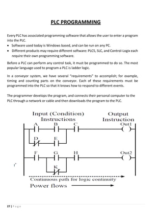
a phase converter having single-phase converter input and three-phase inverter output.[7]
Controller advances have exploited dramatic increases in the voltage and current ratings and
switching frequency of solid state power devices over the past six decades. Introduced in
1983, the insulated-gate bipolar transistor (IGBT) has in the past two decades come to
dominate VFDs as an inverter switching device.[9][10][11]
The two other drive control platforms, vector control and direct torque control (DTC), adjust
the motor voltage magnitude, angle from reference and frequency[14]
such as to precisely
control the motor's magnetic flux and mechanical torque.
Operator interface
The operator interface provides a means for an operator to start and stop the motor and
adjust the operating speed. Additional operator control functions might include reversing,
and switching between manual speed adjustment and automatic control from an
external process control signal. The operator interface often includes
an alphanumeric display and/or indication lights and meters to provide information about
the operation of the drive. An operator interface keypad and display unit is often provided
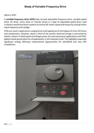
on the front of the VFD controller as shown in the photograph above. The keypad display can](https://image.slidesharecdn.com/81651e6b-d374-49db-963d-e40fcfd6e714-160606122947/85/Siddharth-KIIT-38-320.jpg)


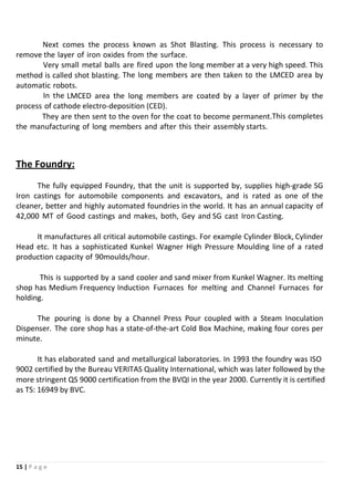
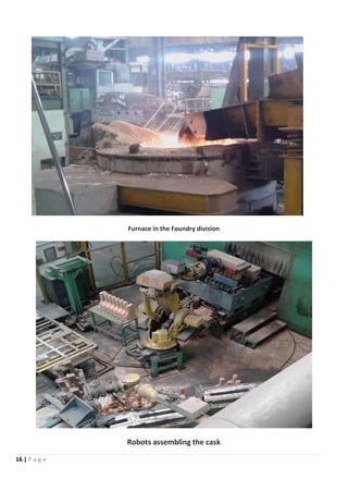
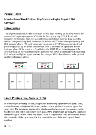
This document provides an overview of Tata Motors and its manufacturing facilities. It discusses the company's history and various divisions at its Jamshedpur plant in India, including the Cab and Cowl Factory, Paint Shop, PRIMA division, Truck Factory, Foundry, Engine Factory, and Central Tool Room. It then provides more details on the manufacturing processes for cabs/cowls at the Cab and Cowl Factory and Paint Shop.


