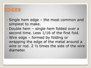
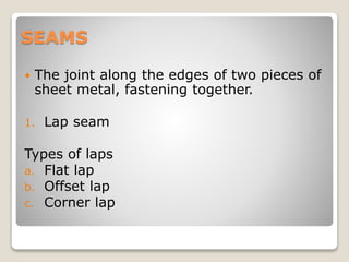
1. The document discusses various sheet metal edges, seams, and pattern development methods. Common edges include single hem, double hem, and wire edge. Common seams include lap seams, grooved seams, dovetail seams, and pittsburg lock seams. Pattern development methods include the parallel line method, triangulation method, and radial line method.
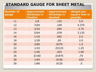
2. The document also provides a table with US standard sheet metal gauges showing approximate thickness and weight for various gauges ranging from 11 to 30.
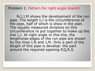
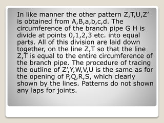
3. An example is given for developing patterns for a right angle branch using the parallel line method of development. Key steps include dividing pipe circumferences into equal parts and transferring division points to