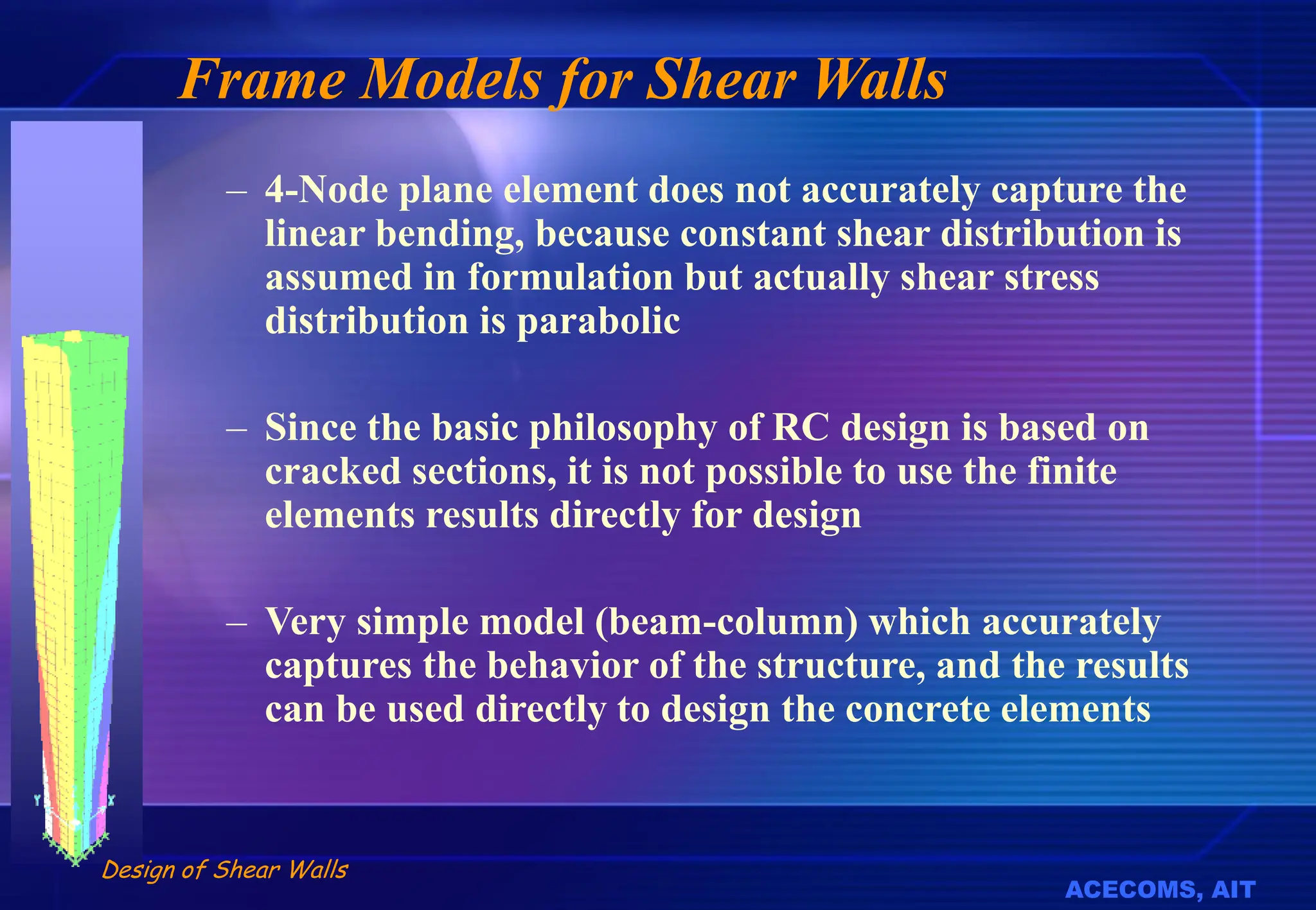
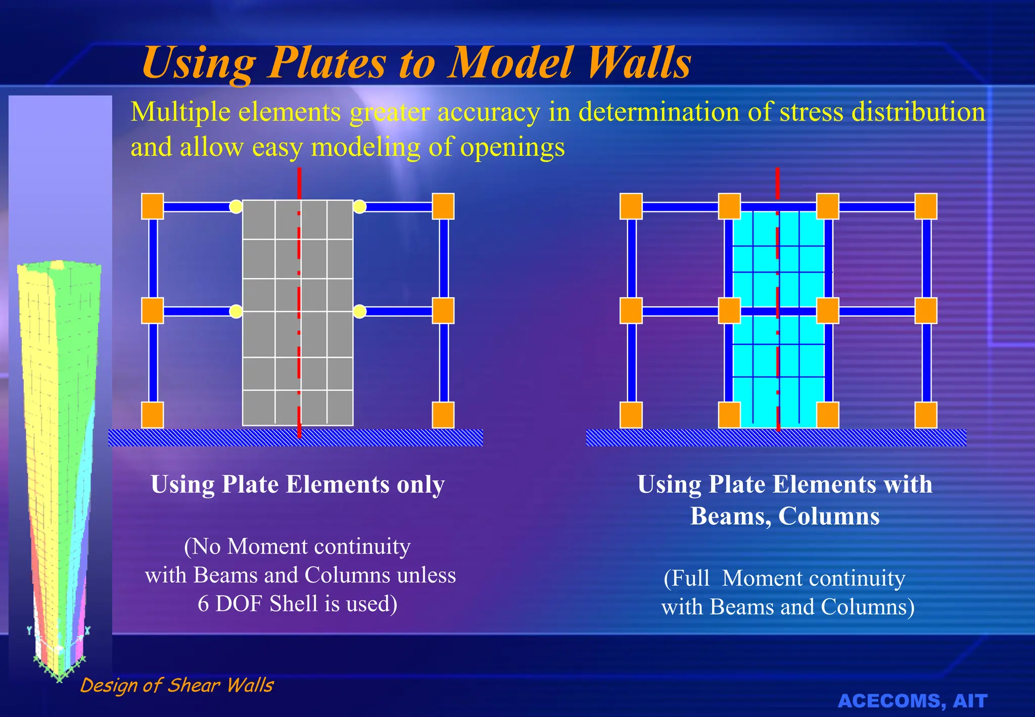
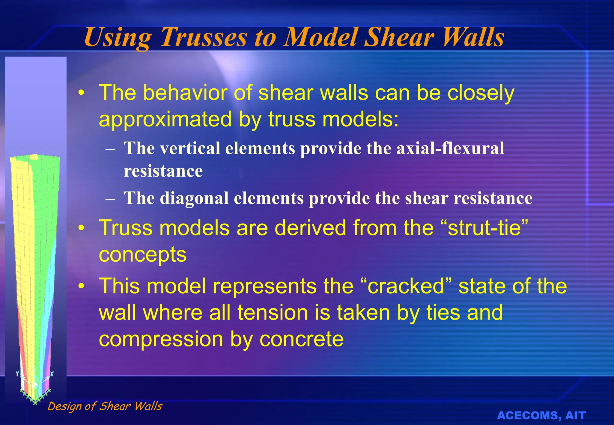
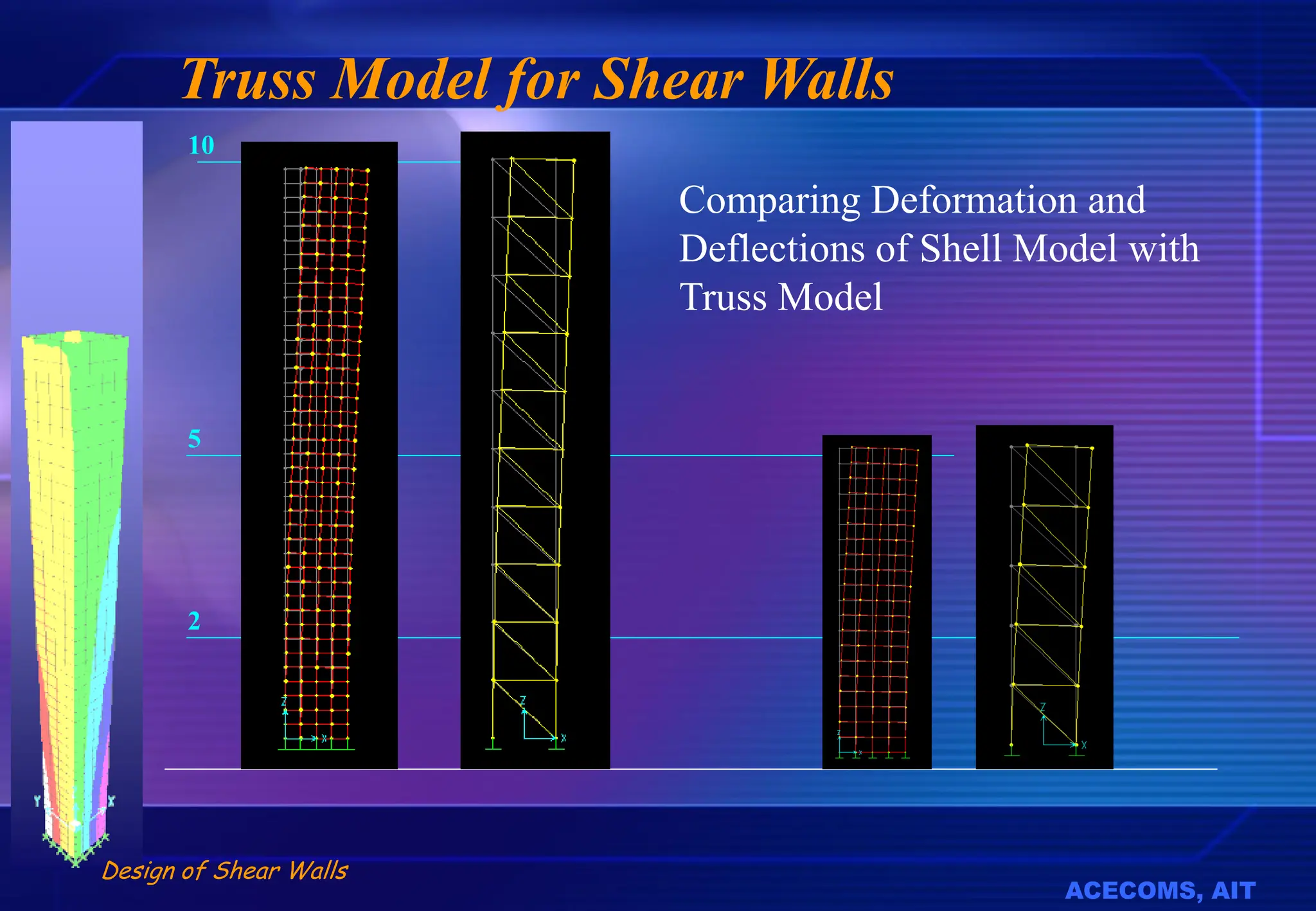
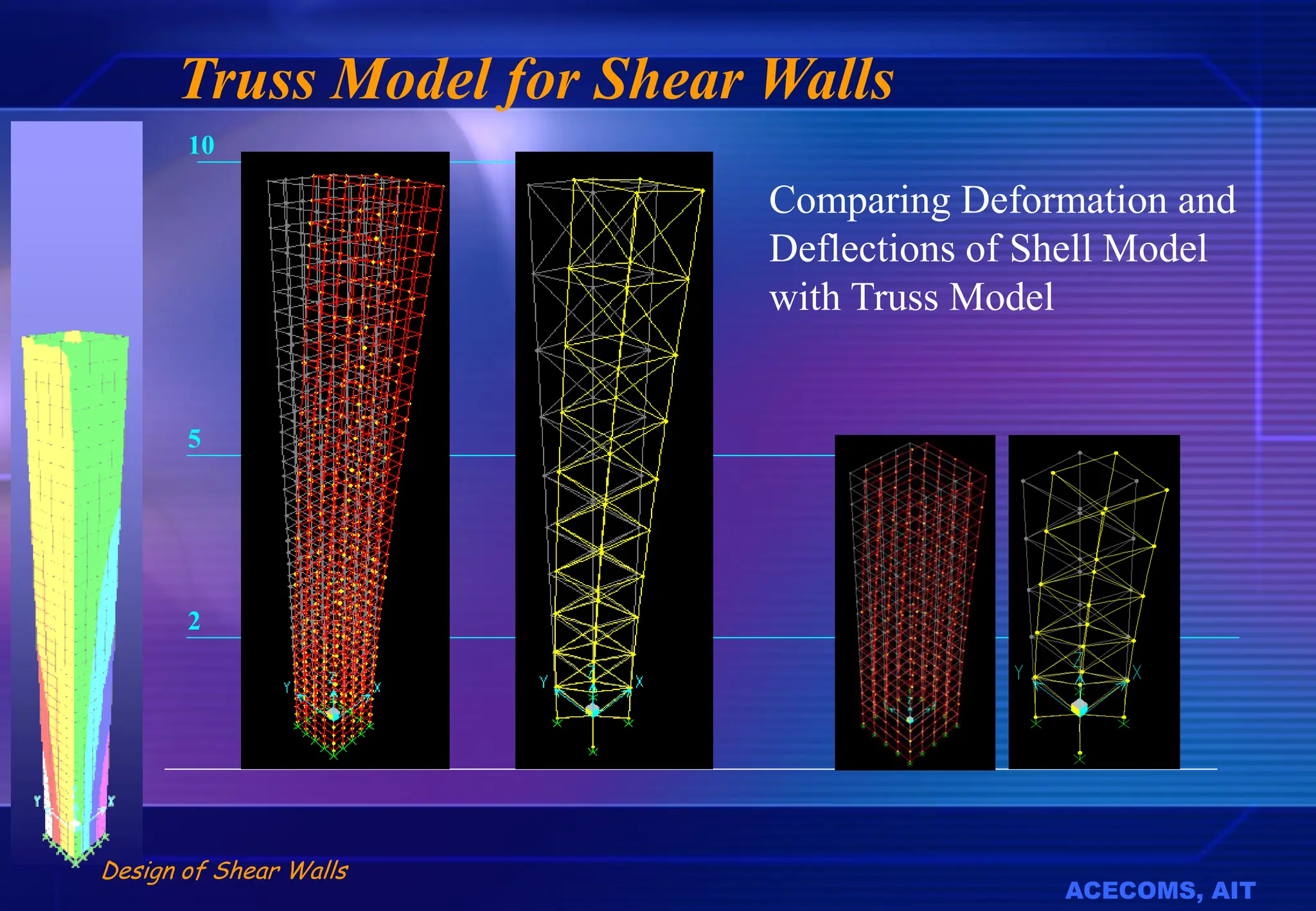
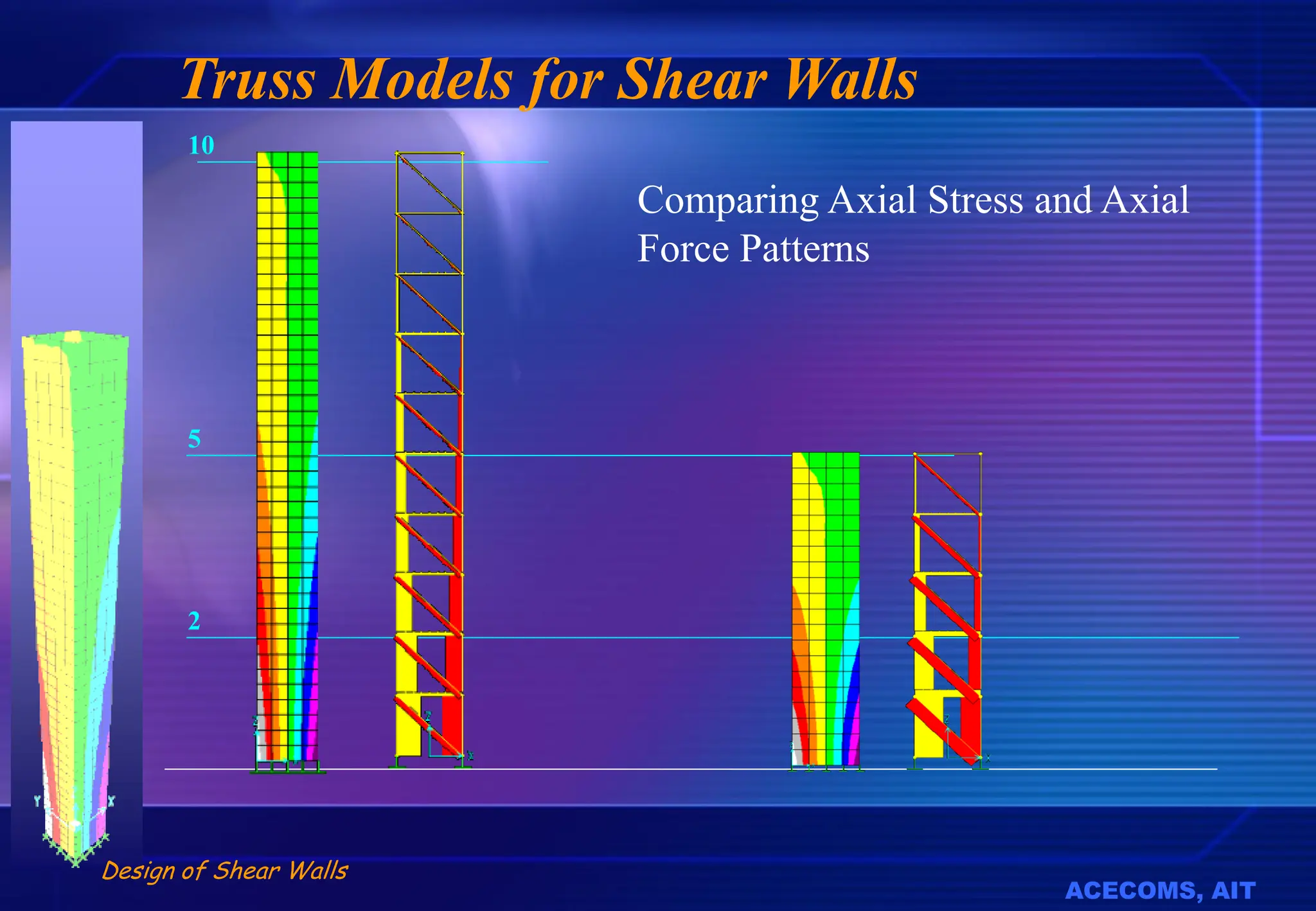
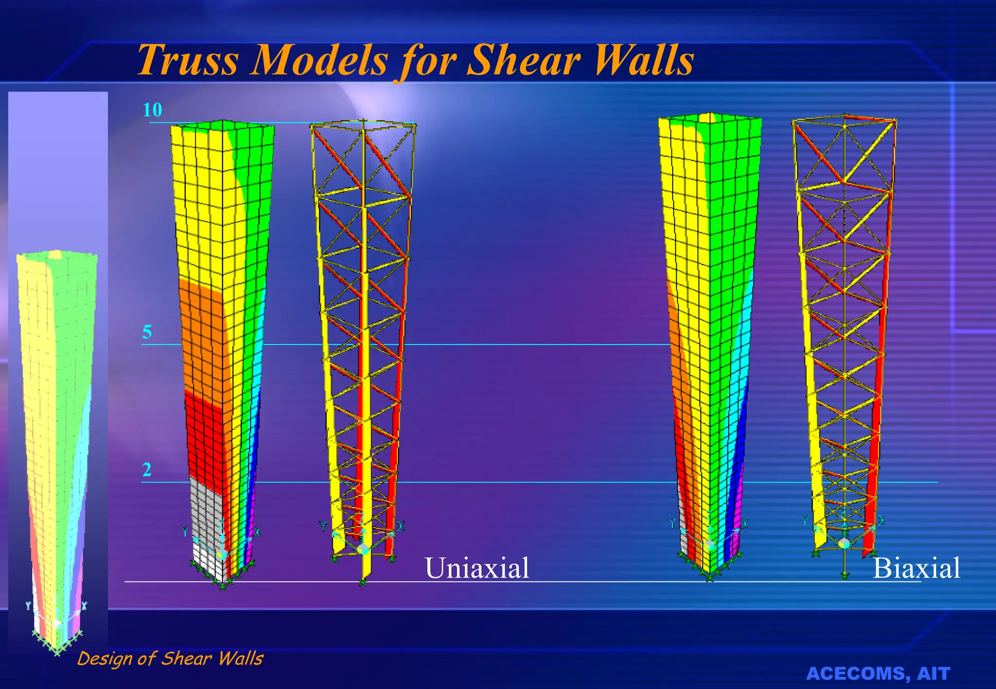
SlideShare a Scribd company logo
1 of 97
Download to read offline
Buddhi S. Sharma
ACECO MS, AIT
Design of Shear Walls Using ETABS
O-SCAAD-1
May 21, 2002, AIT, Bangkok
ACECOMS, AIT
Design of Shear Walls
The Basic Issues
• What is a Shear Wall?
• Modeling and analysis issues
– Transfer of loads to shear walls
– Modeling of shear walls in 2D
– Modeling of shear Walls in 3D
– Interaction of shear-walls with frames
• Design and detaining issues
– Determination of rebars for flexure
– Determination of rebars for shear
– Detailing of rebars near openings and corners
– Design and detailing of connection between various components
of cellular shear walls
Shear Wall
Definition
ACECOMS, AIT
Design of Shear Walls
What is a Shear Wall?
• How can we “tell” when a member is a shear
wall
• Is the definition based on?
– Intended Use
– Shape in Cross-section
– Geometry in Elevation
– Loading Type and Intensity
– Behavior and Theory
– Location, Direction, Orientation
ACECOMS, AIT
Design of Shear Walls
Shear Wall or Column
Wall Column
ACECOMS, AIT
Design of Shear Walls
Shear Wall or Frame
Shear Wall Frame
Shear Wall or Frame ?
ACECOMS, AIT
Design of Shear Walls
Shear Wall or Truss?
ACECOMS, AIT
Design of Shear Walls
Planner Walls
Planer Stiffened Regular
Openings
Irregular Openings
ACECOMS, AIT
Design of Shear Walls
Cellular Walls
Location and
Layout of
Shear Walls
ACECOMS, AIT
Design of Shear Walls
Purpose of Shear Walls
• Resist the lateral loads for medium rise buildings
up to 40 floors
– Reduce total deflection and story drift
– Increase lateral stiffness
– Reduce moments in columns and floor members due to
lateral loads
– Reduce the overall cost of the structural system
– Can also serve as elevator shafts, service ducts, etc,
ACECOMS, AIT
Design of Shear Walls
Loads Transferred to Shear Walls
• Distribution of lateral loads to individual shear walls, to
moment resisting frames, to wall-frames and to
individual columns depends on:
– Stiffness of each column and wall
– Lateral stiffness of each frame or wall frame
– Location of the the vertical unit with respect to the load building
lateral stiffness center
– Location of the load center with respect to the stiffness center
– The geometry and in-plane stiffness of the floor slab system
ACECOMS, AIT
Design of Shear Walls
Load Transferred to Shear Walls
f
Building Plan
D
F
Stiffness
Center
Load Center
?
?
ACECOMS, AIT
Design of Shear Walls
How to Locate the Walls
• Reduce the eccentricity between the stiffness center and
the load center
– Consider Eccentricity due to Wind Loads, depending on overall
geometry of the structure
– Consider Eccentricity due to Earthquake Loads, depending on
Mass Distribution
– Consider Eccentricity not only at foundation level but at various
heights
• Reduce the in-plane bending in the slab system and
Evenly distribute the stiffness in both directions
• Use building layout in plan to enhance overall stiffness
and reduce need for shear walls
ACECOMS, AIT
Design of Shear Walls
How to Check Eccentricity!
• For Wind Loads
– Apply Wind load in X-Direction and check nodal displacements. If
displacement in Y-Directions are nearly zero or very small, then
there is no eccentricity between wind load and and stiffness center
in Y-direction
– Repeat the same for Y-Direction Load
• Seismic Loads
– Assign the Mass properties to the building and carryout a Modal
Analysis: If the first two modes are Translational, and third mode is
Torsional, then there is no eccentricity between the mass center and
Stiffness Center in Both Directions
ACECOMS, AIT
Design of Shear Walls
Eccentric and Concentric Response
F
No Eccentricity
D
F
Eccentric Shear Wall
ACECOMS, AIT
Design of Shear Walls
Eccentric and Concentric Response
Mode-1 Mode-2 Mode-3
Symmetrical Mass and
Stiffness
Unsymmetrical Mass and
Stiffness
ACECOMS, AIT
Design of Shear Walls
Avoid Eccentricity in Plan
Or
ACECOMS, AIT
Design of Shear Walls
Reduce In-plane Bending in Floor
ACECOMS, AIT
Design of Shear Walls
Vertical Irregularity
Expansion
Joint
Balanced Shear
Walls at All Levels
No Shear Walls Using Expansion
Joints to eliminate
some walls
ACECOMS, AIT
Design of Shear Walls
Using Efficient Building Plan Shape
Shear Wall
Behavior
ACECOMS, AIT
Design of Shear Walls
Shear Wall and Frame Behavior
Shear Wall Behavior Frame Behavior
ACECOMS, AIT
Design of Shear Walls
2
5
10
Axial Stresses in Planer Walls
ACECOMS, AIT
Design of Shear Walls
2
5
10
Axial Stresses in Cellular Walls
Uniaxial Bending
ACECOMS, AIT
Design of Shear Walls
2
5
10
Axial Stresses in Cellular Walls
Biaxial Bending
Modeling of
Shear Walls
ACECOMS, AIT
Design of Shear Walls
Modeling of Planer Walls
Using Beam and Column Using Panels, Plates and Beams
Using Truss
ACECOMS, AIT
Design of Shear Walls
Modeling of Shear Walls
Using Beam Elements
ACECOMS, AIT
Design of Shear Walls
Frame Models for Shear Walls
– 4-Node plane element does not accurately capture the
linear bending, because constant shear distribution is
assumed in formulation but actually shear stress
distribution is parabolic
– Since the basic philosophy of RC design is based on
cracked sections, it is not possible to use the finite
elements results directly for design
– Very simple model (beam-column) which accurately
captures the behavior of the structure, and the results
can be used directly to design the concrete elements
ACECOMS, AIT
Design of Shear Walls
Modeling of Walls using 1D Elements
L
t x h
L
t
H2
H1
Simple beam
elements
L
t
Beam elements
with rigid ends
Beam elements
in “Truss Model”
ACECOMS, AIT
Design of Shear Walls
Frame Model for Planer Walls
Rigid Zones
• Specially Suitable when H/B is
more than 5
• The shear wall is represented
by a column of section “B x t”
• The beam up to the edge of the
wall is modeled as normal
beam
• The “column” is connected to
beam by rigid zones or very
large cross-section
B
H
t
ACECOMS, AIT
Design of Shear Walls
Frame Models for Cellular Walls
• Difficult to extend the concept to
Non-planer walls
• Core Wall must be converted to
“equivalent” column and
appropriate “rigid” elements
• Can be used in 2D analysis but
more complicated for 3D analysis
• After the core wall is converted to
planer wall, the simplified
procedure cab used for modeling
B
H
t
B
H
2t
t
ACECOMS, AIT
Design of Shear Walls
Modeling of Shear Walls
Using Plate/Shell Elements
1
2
3
U1, R1
Node 3
U3, R3
U2, R2
U1, R1
Node 1
U3, R3 U2, R2
U1, R1
Node 4
U3, R3
U2, R2
U1, R1
Node 2
U3, R3
U2, R2
Shell
ACECOMS, AIT
Design of Shear Walls
Modeling Walls using 2D Elements
• Walls are subjected to in-plane deformations so
2D elements that have transnational DOF need
to be used
• A coarse mesh can be used to capture the
overall stiffness and deformation of the wall
• A fine mesh should be used to capture in-plane
bending or curvature
• General Shell Element or Membrane Elements
can be used to model Shear Walls
ACECOMS, AIT
Design of Shear Walls
Modeling Walls Using Membrane
Nodes: 4
DOFs: 2 (or 3) DOFs /Node Ux and Uy
2-Translation, 0 or 1 rotation
Dimension: 2 dimension element
Shape: Regular / Irregular
Properties: Modulus of Elasticity(E),
Poisson ratio(v),
Thickness( t )
ACECOMS, AIT
Design of Shear Walls
Modeling Walls using Shell Elements
Nodes: 4
DOFs: 5 or 6 DOFs /Node Ux and Uy
3 Translation, 2 or 3 rotation
Dimension: 2 dimension element
Shape: Regular / Irregular
Properties: Modulus of Elasticity(E),
Poisson ratio(v),
Thickness( t )
1
2
3
U1, R1
Node 3
U3, R3
U2, R2
U1, R1
Node 1
U3, R3 U2, R2
U1, R1
Node 4
U3, R3
U2, R2
U1, R1
Node 2
U3, R3
U2, R2
Shell
ACECOMS, AIT
Design of Shear Walls
Using Panel/ Plate Elements
Modeling Shear-Walls
using Panels only
(No Moment continuity
with Beams and Columns unless
6 DOF Shell is used)
Modeling Shear-Walls using Panels,
Beams, Columns
(Full Moment continuity
with Beams and Columns is restored by
using additional beams)
ACECOMS, AIT
Design of Shear Walls
Using Plates to Model Walls
Multiple elements greater accuracy in determination of stress distribution
and allow easy modeling of openings
Using Plate Elements only
(No Moment continuity
with Beams and Columns unless
6 DOF Shell is used)
Using Plate Elements with
Beams, Columns
(Full Moment continuity
with Beams and Columns)
ACECOMS, AIT
Design of Shear Walls
Connecting Walls to Slab
In general the mesh in the slab
should match with mesh in the wall
to establish connection
Some software automatically
establishes connectivity by using
constraints or “Zipper” elements
“Zipper”
ACECOMS, AIT
Design of Shear Walls
Modeling of Shear Walls
Using Truss Models
C
t
B
t x 2t
t x t
ACECOMS, AIT
Design of Shear Walls
Using Trusses to Model Shear Walls
• The behavior of shear walls can be closely
approximated by truss models:
– The vertical elements provide the axial-flexural
resistance
– The diagonal elements provide the shear resistance
• Truss models are derived from the “strut-tie”
concepts
• This model represents the “cracked” state of the
wall where all tension is taken by ties and
compression by concrete
ACECOMS, AIT
Design of Shear Walls
2
5
10
Truss Model for Shear Walls
Comparing Deformation and
Deflections of Shell Model with
Truss Model
ACECOMS, AIT
Design of Shear Walls
Truss Model for Shear Walls
2
5
10
Comparing Deformation and
Deflections of Shell Model
with Truss Model
ACECOMS, AIT
Design of Shear Walls
2
5
10
Truss Models for Shear Walls
Comparing Axial Stress and Axial
Force Patterns
ACECOMS, AIT
Design of Shear Walls
2
5
10
Truss Models for Shear Walls
Uniaxial Biaxial
ACECOMS, AIT
Design of Shear Walls
How to Construct Truss Models
• For the purpose of analysis, assume the
main truss layout based on wall width
and floor levels
• Initial member sizes can be estimated as
t x 2t for main axial members and t x t for
diagonal members
• Use frame elements to model the truss.
It is not necessary to use truss
elements
• Generally single diagonal is sufficient for
modeling but double diagonal may be
used for easier interpretation of results
• The floor beams and slabs can be
connected directly to truss elements
C
t
B
t x 2t
t x t
ACECOMS, AIT
Design of Shear Walls
Modeling of Shear Walls
Openings in Shear Walls
ACECOMS, AIT
Design of Shear Walls
Very Large Openings
may convert the Wall
to Frame
Very Small Openings
may not alter wall
behavior
Openings in Shear Walls
Medium Openings
may convert shear
wall to Pier and
Spandrel System
Pier Pier
Spandrel
Column
Beam
Wall
ACECOMS, AIT
Design of Shear Walls
Openings in Shear Walls - Cellular
2
5
ACECOMS, AIT
Design of Shear Walls
Openings in Shear Walls - Planer
ACECOMS, AIT
Design of Shear Walls
Modeling Walls with Opening
Plate-Shell Model Rigid Frame Model Truss Model
ACECOMS, AIT
Design of Shear Walls
Frame Model of Shear Walls
3 DOF
per rigid zone
Rigid Zones
Beams
Columns
A: Shear Wall with Line Loads B: Finite Element Model
C: Define Beams & Columns D: Beam-Column Model
Based on Concept proposed by E.L. Wilson
Design of
Shear Walls
ACECOMS, AIT
Design of Shear Walls
Basic Design Considerations
• Main Shear Wall
– Flexural Design
– Shear Design
• Spandrels and Links
– Flexural Design
– Shear Design
• Ductility Considerations
• Anchorage with Footings
• Connection with Floor Slab/ Beams
ACECOMS, AIT
Design of Shear Walls
Flexural Design
ACECOMS, AIT
Design of Shear Walls
Flexural Design
As Single Flexural Member
ACECOMS, AIT
Design of Shear Walls
Designing as A Flexural Member
• Approach
– Design the Wall as “Big Column”
– Follow the normal axial-flexural
concept and provisions
• Input Needed
– P, Mx , (and My)
– Wall Dimensions
• Problems
– Does not consider the non-linear
strain distribution
– In efficient rebar distribution
ACECOMS, AIT
Design of Shear Walls
Design Procedure
1. Obtain Design Actions from Analysis
2. Assume rebar sizes, amount and distribution
3. Determine Cross-section capacity as column in
form of Interaction Surfaces and Curves
4. Check if all action sets (P, Mx, My) fall within
the interaction surface. The extreme values
should be near the surface
5. If required, revise cross-section and repeat
ACECOMS, AIT
Design of Shear Walls
Getting Result from Frame Model
Design actions (P, Mx, My and V) are obtained directly
Vx
Vy
P
Mx
My
V
P
M
ACECOMS, AIT
Design of Shear Walls
Getting Results from Truss Model
C
T
D
Tension
Member
Compression
Member
V
P
M
)
cos(
)
sin(
)
sin(



D
V
x
D
Cx
Tx
M
D
C
T
P
d
c
t







xc
xt
xd
ACECOMS, AIT
Design of Shear Walls
Getting Results From Shell Model
f1, f2, …..fn are the nodal stresses at
section A-A , obtained from analysis
CL of wall
A
A










n
i
i
i
i
n
i
i
n
i
i
i
i
i
v
A
V
x
F
M
F
P
f
A
F
1
1
1
f1
f2
f3
f4
f5
C
T
1
x
x1
t
V
P
M
ACECOMS, AIT
Design of Shear Walls
Assuming Reinforcement
• Assume larger bars on the corners
• Assume more bars on predominant tension
direction/ location
• Assume uniform reinforcement on wall sides
• Total Rebars ratio should preferably be more
than 0.8% and less than 3% for economical
design
ACECOMS, AIT
Design of Shear Walls
Obtaining Section Capacity Curves
• Can be done manually by using linear strain
distribution and equilibrium conditions
– Generate few control points on the curve
– Difficult to apply for Cellular and non rectangular walls
• Can be obtained in more complete form using
Software
– CSI-Section Builder
– GEAR – Column Section Module
– PCA Column
ACECOMS, AIT
Design of Shear Walls
Interaction Curves - Uniaxial
The curve is generated by varying
the neutral axis depth






















zi
N
i
si
z A
c
ny
N
i
si
A
c
nx
d
A
f
dz
da
f
M
A
f
da
f
N
si
b
si
b
1
1
.
)
(
)
(




Safe
Un-safe
ACECOMS, AIT
Design of Shear Walls
Interaction Surface - Biaxial
The surface is
generated by
changing Angle and
Depth of Neutral
Axis
+ Mz
- My
+P
+ My
- Mz
Pu
A cross-section of
interaction surface at P u
Safe
Un-safe
 
 
 































 

 
  



...
)
,
(
1
...
.
,
1
...
)
,
(
1
...
.
,
1
...
)
,
(
1
...
,
1
1
2
1
3
1
2
1
2
1
2
1
1
i
n
i
i
i
x y
y
i
n
i
i
i
x y
x
x y
n
i
i
i
z
x
y
x
A
x
dy
dx
y
x
M
y
y
x
A
y
dy
dx
y
x
M
y
x
A
dy
dx
y
x
N















ACECOMS, AIT
Design of Shear Walls
Interaction Surface and Curves
ACECOMS, AIT
Design of Shear Walls
Narrow Planner Walls
The capacity is almost completely un-
axial
Moment capacity can be increased by
providing Rebars at the corners
ACECOMS, AIT
Design of Shear Walls
Cellular Wall – No Opening
The capacity is
almost completely
biaxial
ACECOMS, AIT
Design of Shear Walls
Single Cell Walls
ACECOMS, AIT
Design of Shear Walls
Double Cell Walls
ACECOMS, AIT
Design of Shear Walls
Flexural Design
Using Axial Zones
ACECOMS, AIT
Design of Shear Walls
Design Walls in Zones
• Basic Concept
– Design the wall to resist the external actions by
compression, tension and shear zones
– More intuitive and more economical
– Zone of high tension designed as tension member
with concentrated rebars
– Zone of high compression designed as compression
member with appropriate rebar limits
– Zone of low stress design as wall with nominal wall
rebars
ACECOMS, AIT
Design of Shear Walls
Designing as Axial Zones
ACECOMS, AIT
Design of Shear Walls
Design Procedure
1. Obtain Design Actions from Analysis
2. Compute Axial Forces
3. For each axial force, assume section, assume
rebars and check capacity
4. If capacity not enough, revise section, re-
compute Axial Forces, and continue until
required section for each force is designed
5. Provide nominal wall reinforcement in between
the axial zones
ACECOMS, AIT
Design of Shear Walls
Getting Result from Frame Model
Compute Forces from Actions
P
Mx
My
P
M
2
2
1
1
/
5
.
0
/
5
.
0
x
M
P
F
x
M
P
F




i
y
i
x
i
x
M
y
M
P
F 


4
x1 x2 yi
F1 F2
Fi
ACECOMS, AIT
Design of Shear Walls
Getting Results from Truss Model
C
T
D
Tension
Member
Compression
Member
xc
xt
xd
Results obtained from truss
analysis can be used Directly
F1 = T
F2 = C
ACECOMS, AIT
Design of Shear Walls
Getting Results From Shell Model
f1, f2, …..fn are the nodal stresses at
section A-A , obtained from analysis
CL of wall
A
A
i
i
i
i
i
f
A
F
t
x
A


f1
f2
f3
f4
f5
C
T
1
x
x1
t
F1=T F2=C
ACECOMS, AIT
Design of Shear Walls
Axial Zone Model – Planer Wall
ACECOMS, AIT
Design of Shear Walls
Axial Zones for Box Wall
ACECOMS, AIT
Design of Shear Walls
Design as Truss: Strut and Tie
• Directly design the
tension members for
reinforcement
• Directly design the
compression members
as columns
• The design is similar to
the “Axial Zones”
concept
ACECOMS, AIT
Design of Shear Walls
Concrete Shear Wall Design in ETABS
• 2D wall pier design and boundary-member checks
• 2D wall spandrel design
• 3D wall pier check for provided reinforcement
• Graphical Section Designer for concrete rebar location
• Graphical display of reinforcement and stress ratios
• Interactive design and review
• Summary and detailed reports including database
formats
ACECOMS, AIT
Design of Shear Walls
Shear Design
Spandrel
Pier
ACECOMS, AIT
Design of Shear Walls
Shear Design Procedure
• For Walls without Openings
– Design the wall as piers
• For Walls with Openings
– Design the Piers, the vertical part
– Design the Spandrels, the horizontal part
ACECOMS, AIT
Design of Shear Walls
Shear Design of Pier
• Determine Concrete
shear capacity, Vc
• Check if Vc exceeds the
limit, if it does, section
needs to be revised
• Determine steel Rebars
for Vs=V-Vc
• Check additional steel for
seismic requirements
p
L
p
t
ACECOMS, AIT
Design of Shear Walls
ACI Equations for Pier Design
   
p
p
u
p
p
c
LW
c
L
L
.
P
L
.
t
f
R
.
V
4
8
0
8
0
3
3 


 
p
p
p
u
u
p
p
u
c
LW
p
c
LW
c L
.
t
L
V
M
Abs
t
L
P
.
f
R
.
L
f
R
.
V 8
0
2
2
0
25
1
6
0




































 
 
p
ys
c
u
v
L
.
f
V
V
Abs
A
8
0



   
p
p
c
LW
u
L
.
t
f
R
V
Abs
8
0
10 


Basic Concrete Shear Capacity
Concrete not to Exceed the limit
Area of Steel Computed as
ACECOMS, AIT
Design of Shear Walls
Shear Design for Spandrel
top
r
d 
bot
r
d 
a
c
s
h
s
t
s
h
s
L
Elevation
Section
• Determine Concrete
shear capacity, Vc
• Check if Vc exceeds the
limit, if it does, section
needs to be revised
• Determine steel Rebars
for Vs=V-Vc
• Check additional steel for
seismic requirements
ACECOMS, AIT
Design of Shear Walls
ACI Equations for Spandrel Design
s
s
c
LW
c d
t
f
R
V

 2
c
u
c
n
s V
V
V
V
V 




s
s
c
LW
s d
t
f
R
V 
 8
s
ys
s
v
d
f
V
A 
Basic Concrete Shear Capacity
Concrete not to Exceed the limit
Area of Steel Computed as
Check for minimum steel and spacing etc.
ACECOMS, AIT
Design of Shear Walls
ACI Equations for Spandrel Design
5

s
s
d
L
When and c
u
V
.
V
5
0


0
50


min
h
ys
s
min
v
A
f
t
A
When 5

s
s
d
L
and c
u
V
.
V
5
0


0

 min
h
min
v A
A
When 5
2 

s
s
d
L
Check
s
s
c
LW
s
s
u
d
t
f
R
d
L
V










 10
3
2
 s
min
h
s
min
v
t
.
A
t
.
A
0025
0
0015
0


ACECOMS, AIT
Design of Shear Walls
Notations for Shear Design
top
r
d 
bot
r
d 
s
h
s
t = Thickness of Spandrel
= Distance from top of spandrel to the centroid of top reinforcing
= Distance from bottom of spandrel to the centroid of bottom reinforcing
= Total depth of spandrel
LW
R = Shear reduction factor as specified in the concrete material properties for
light weight concrete.
s
d = Effective depth of spandrel
s
V = Portion of Shear force in spandrel carried by reinforcing steel
c
V = Portion of Shear force in spandrel carried by concrete
s
L = Length of Spandrel
ACECOMS, AIT
Design of Shear Walls
Notations for Shear Design
p
t = Thickness of Pier
p
L = Length of Pier
min
v
A = Minimum vertical required area of distributed shear reinforcing
min
h
A = Minimum horizontal required area of distributed shear reinforcing
n
V = Nominal Shear strength
ys
f = Shear yield strength of steel
c
f  = Concrete Compressive Strength
Detailing of
Shear Walls
ACECOMS, AIT
Design of Shear Walls
Wall Section
• Place more reinforcement at the ends and distribute the
remaining in the middle portion
• Confine the Rebars at the end for improved ductility and
increased moment capacity
Option -1
Option -2
Option -3
ACECOMS, AIT
Design of Shear Walls
Effect of Rebar Layout
Moment Capacity for 1% Rebars
a) Uniform Distribution
b) Concentrated Bars
Max M= 380
Max M= 475
Nearly 25% increase for same steel
ACECOMS, AIT
Design of Shear Walls
Wall Section
• Place more reinforcement at
the corners and distribute the
remaining in the middle
portion
• Confine the Rebars at the
corners for improved
ductility and increased
moment capacity
• Provide U-Bars at the
corners for easier
construction and improved
laps
ACECOMS, AIT
Design of Shear Walls
Effect of Rebar Layout
Moment Capacity for 1% Rebars
a) Uniform Distribution
b) Concentrated Bars
Nearly 20% increase for same steel
Max M= 16500
Max M= 19600
ACECOMS, AIT
Design of Shear Walls
Rebar Detailing For Openings

More Related Content

Similar to Shear wall design - muros de corte Etabs

Aeons
AeonsAeons
AeonsPixel
 
Prefabricated components
Prefabricated componentsPrefabricated components
Prefabricated componentsSofia Rajesh
 
PRE-CAST-CONSTRUCTION.pptx
PRE-CAST-CONSTRUCTION.pptxPRE-CAST-CONSTRUCTION.pptx
PRE-CAST-CONSTRUCTION.pptxVinayak247538
 
IRJET- Comparative Study of Flat Slab and Conventional Slab Structure wit...
IRJET-  	  Comparative Study of Flat Slab and Conventional Slab Structure wit...IRJET-  	  Comparative Study of Flat Slab and Conventional Slab Structure wit...
IRJET- Comparative Study of Flat Slab and Conventional Slab Structure wit...IRJET Journal
 
PRE-CAST-CONSTRUCTION.pptx
PRE-CAST-CONSTRUCTION.pptxPRE-CAST-CONSTRUCTION.pptx
PRE-CAST-CONSTRUCTION.pptxLokeswarSaha1
 
Seismic Behaviour of Reinforced Concrete Flat Plate Systems
Seismic Behaviour of Reinforced Concrete Flat Plate SystemsSeismic Behaviour of Reinforced Concrete Flat Plate Systems
Seismic Behaviour of Reinforced Concrete Flat Plate SystemsIRJET Journal
 
Running Head BRIDGE DESIGN1BRIDGE DESIGN31.docx
Running Head BRIDGE DESIGN1BRIDGE DESIGN31.docxRunning Head BRIDGE DESIGN1BRIDGE DESIGN31.docx
Running Head BRIDGE DESIGN1BRIDGE DESIGN31.docxtoddr4
 
Precast construction
Precast constructionPrecast construction
Precast constructionDivya Vishnoi
 
Civil engineering - thumb rule
Civil engineering - thumb ruleCivil engineering - thumb rule
Civil engineering - thumb ruleBenAdem1
 
Architectural structures shear-wall.ppt
Architectural structures shear-wall.pptArchitectural structures shear-wall.ppt
Architectural structures shear-wall.pptMohdAzharNumaniShah
 
Chapter 5 formwork
Chapter 5 formworkChapter 5 formwork
Chapter 5 formworkKHUSHBU SHAH
 
08 - Portal Frame.pptx
08 - Portal Frame.pptx08 - Portal Frame.pptx
08 - Portal Frame.pptx2022786965
 
Seismic Response of Structure with Single Core
Seismic Response of Structure with Single CoreSeismic Response of Structure with Single Core
Seismic Response of Structure with Single Coreijtsrd
 
Aitc step by-step procedure for pbd of 40-story rc building_overall (20141105)
Aitc step by-step procedure for pbd of 40-story rc building_overall (20141105)Aitc step by-step procedure for pbd of 40-story rc building_overall (20141105)
Aitc step by-step procedure for pbd of 40-story rc building_overall (20141105)Ramil Artates
 
UNIT 2 PREFABRICATION COMPONENTS | CE8022 PREFABRICATED STRUCTURES
UNIT 2 PREFABRICATION COMPONENTS | CE8022 PREFABRICATED STRUCTURESUNIT 2 PREFABRICATION COMPONENTS | CE8022 PREFABRICATED STRUCTURES
UNIT 2 PREFABRICATION COMPONENTS | CE8022 PREFABRICATED STRUCTURESVenkateswaran S
 

Similar to Shear wall design - muros de corte Etabs (20)

Aeons
AeonsAeons
Aeons
 
Prefabricated components
Prefabricated componentsPrefabricated components
Prefabricated components
 
PRE-CAST-CONSTRUCTION.pptx
PRE-CAST-CONSTRUCTION.pptxPRE-CAST-CONSTRUCTION.pptx
PRE-CAST-CONSTRUCTION.pptx
 
IRJET- Comparative Study of Flat Slab and Conventional Slab Structure wit...
IRJET-  	  Comparative Study of Flat Slab and Conventional Slab Structure wit...IRJET-  	  Comparative Study of Flat Slab and Conventional Slab Structure wit...
IRJET- Comparative Study of Flat Slab and Conventional Slab Structure wit...
 
PRE-CAST-CONSTRUCTION.pptx
PRE-CAST-CONSTRUCTION.pptxPRE-CAST-CONSTRUCTION.pptx
PRE-CAST-CONSTRUCTION.pptx
 
Seismic Behaviour of Reinforced Concrete Flat Plate Systems
Seismic Behaviour of Reinforced Concrete Flat Plate SystemsSeismic Behaviour of Reinforced Concrete Flat Plate Systems
Seismic Behaviour of Reinforced Concrete Flat Plate Systems
 
Running Head BRIDGE DESIGN1BRIDGE DESIGN31.docx
Running Head BRIDGE DESIGN1BRIDGE DESIGN31.docxRunning Head BRIDGE DESIGN1BRIDGE DESIGN31.docx
Running Head BRIDGE DESIGN1BRIDGE DESIGN31.docx
 
Precast construction
Precast constructionPrecast construction
Precast construction
 
Civil engineering - thumb rule
Civil engineering - thumb ruleCivil engineering - thumb rule
Civil engineering - thumb rule
 
Framed structures
Framed structures Framed structures
Framed structures
 
Space frame
Space frameSpace frame
Space frame
 
M.Tech PPT.pptx
M.Tech PPT.pptxM.Tech PPT.pptx
M.Tech PPT.pptx
 
Architectural structures shear-wall.ppt
Architectural structures shear-wall.pptArchitectural structures shear-wall.ppt
Architectural structures shear-wall.ppt
 
CHE :- 6 form work (MODULE 3)
CHE :- 6 form work (MODULE 3)CHE :- 6 form work (MODULE 3)
CHE :- 6 form work (MODULE 3)
 
Chapter 5 formwork
Chapter 5 formworkChapter 5 formwork
Chapter 5 formwork
 
08 - Portal Frame.pptx
08 - Portal Frame.pptx08 - Portal Frame.pptx
08 - Portal Frame.pptx
 
Precast concrete
Precast concretePrecast concrete
Precast concrete
 
Seismic Response of Structure with Single Core
Seismic Response of Structure with Single CoreSeismic Response of Structure with Single Core
Seismic Response of Structure with Single Core
 
Aitc step by-step procedure for pbd of 40-story rc building_overall (20141105)
Aitc step by-step procedure for pbd of 40-story rc building_overall (20141105)Aitc step by-step procedure for pbd of 40-story rc building_overall (20141105)
Aitc step by-step procedure for pbd of 40-story rc building_overall (20141105)
 
UNIT 2 PREFABRICATION COMPONENTS | CE8022 PREFABRICATED STRUCTURES
UNIT 2 PREFABRICATION COMPONENTS | CE8022 PREFABRICATED STRUCTURESUNIT 2 PREFABRICATION COMPONENTS | CE8022 PREFABRICATED STRUCTURES
UNIT 2 PREFABRICATION COMPONENTS | CE8022 PREFABRICATED STRUCTURES
 

Recently uploaded

Architect Hassan Khalil Portfolio for 2024
Architect Hassan Khalil Portfolio for 2024Architect Hassan Khalil Portfolio for 2024
Architect Hassan Khalil Portfolio for 2024hassan khalil
 
The Most Attractive Pune Call Girls Budhwar Peth 8250192130 Will You Miss Thi...
The Most Attractive Pune Call Girls Budhwar Peth 8250192130 Will You Miss Thi...The Most Attractive Pune Call Girls Budhwar Peth 8250192130 Will You Miss Thi...
The Most Attractive Pune Call Girls Budhwar Peth 8250192130 Will You Miss Thi...ranjana rawat
 
(ANJALI) Dange Chowk Call Girls Just Call 7001035870 [ Cash on Delivery ] Pun...
(ANJALI) Dange Chowk Call Girls Just Call 7001035870 [ Cash on Delivery ] Pun...(ANJALI) Dange Chowk Call Girls Just Call 7001035870 [ Cash on Delivery ] Pun...
(ANJALI) Dange Chowk Call Girls Just Call 7001035870 [ Cash on Delivery ] Pun...ranjana rawat
 
(SHREYA) Chakan Call Girls Just Call 7001035870 [ Cash on Delivery ] Pune Esc...
(SHREYA) Chakan Call Girls Just Call 7001035870 [ Cash on Delivery ] Pune Esc...(SHREYA) Chakan Call Girls Just Call 7001035870 [ Cash on Delivery ] Pune Esc...
(SHREYA) Chakan Call Girls Just Call 7001035870 [ Cash on Delivery ] Pune Esc...ranjana rawat
 
MANUFACTURING PROCESS-II UNIT-5 NC MACHINE TOOLS
MANUFACTURING PROCESS-II UNIT-5 NC MACHINE TOOLSMANUFACTURING PROCESS-II UNIT-5 NC MACHINE TOOLS
MANUFACTURING PROCESS-II UNIT-5 NC MACHINE TOOLSSIVASHANKAR N
 
Introduction to Multiple Access Protocol.pptx
Introduction to Multiple Access Protocol.pptxIntroduction to Multiple Access Protocol.pptx
Introduction to Multiple Access Protocol.pptxupamatechverse
 
(RIA) Call Girls Bhosari ( 7001035870 ) HI-Fi Pune Escorts Service
(RIA) Call Girls Bhosari ( 7001035870 ) HI-Fi Pune Escorts Service(RIA) Call Girls Bhosari ( 7001035870 ) HI-Fi Pune Escorts Service
(RIA) Call Girls Bhosari ( 7001035870 ) HI-Fi Pune Escorts Serviceranjana rawat
 
VIP Call Girls Service Kondapur Hyderabad Call +91-8250192130
VIP Call Girls Service Kondapur Hyderabad Call +91-8250192130VIP Call Girls Service Kondapur Hyderabad Call +91-8250192130
VIP Call Girls Service Kondapur Hyderabad Call +91-8250192130Suhani Kapoor
 
(PRIYA) Rajgurunagar Call Girls Just Call 7001035870 [ Cash on Delivery ] Pun...
(PRIYA) Rajgurunagar Call Girls Just Call 7001035870 [ Cash on Delivery ] Pun...(PRIYA) Rajgurunagar Call Girls Just Call 7001035870 [ Cash on Delivery ] Pun...
(PRIYA) Rajgurunagar Call Girls Just Call 7001035870 [ Cash on Delivery ] Pun...ranjana rawat
 
Porous Ceramics seminar and technical writing
Porous Ceramics seminar and technical writingPorous Ceramics seminar and technical writing
Porous Ceramics seminar and technical writingrakeshbaidya232001
 
main PPT.pptx of girls hostel security using rfid
main PPT.pptx of girls hostel security using rfidmain PPT.pptx of girls hostel security using rfid
main PPT.pptx of girls hostel security using rfidNikhilNagaraju
 
Decoding Kotlin - Your guide to solving the mysterious in Kotlin.pptx
Decoding Kotlin - Your guide to solving the mysterious in Kotlin.pptxDecoding Kotlin - Your guide to solving the mysterious in Kotlin.pptx
Decoding Kotlin - Your guide to solving the mysterious in Kotlin.pptxJoão Esperancinha
 
Software Development Life Cycle By Team Orange (Dept. of Pharmacy)
Software Development Life Cycle By  Team Orange (Dept. of Pharmacy)Software Development Life Cycle By  Team Orange (Dept. of Pharmacy)
Software Development Life Cycle By Team Orange (Dept. of Pharmacy)Suman Mia
 
College Call Girls Nashik Nehal 7001305949 Independent Escort Service Nashik
College Call Girls Nashik Nehal 7001305949 Independent Escort Service NashikCollege Call Girls Nashik Nehal 7001305949 Independent Escort Service Nashik
College Call Girls Nashik Nehal 7001305949 Independent Escort Service NashikCall Girls in Nagpur High Profile
 
the ladakh protest in leh ladakh 2024 sonam wangchuk.pptx
the ladakh protest in leh ladakh 2024 sonam wangchuk.pptxthe ladakh protest in leh ladakh 2024 sonam wangchuk.pptx
the ladakh protest in leh ladakh 2024 sonam wangchuk.pptxhumanexperienceaaa
 
Introduction and different types of Ethernet.pptx
Introduction and different types of Ethernet.pptxIntroduction and different types of Ethernet.pptx
Introduction and different types of Ethernet.pptxupamatechverse
 
Extrusion Processes and Their Limitations
Extrusion Processes and Their LimitationsExtrusion Processes and Their Limitations
Extrusion Processes and Their Limitations120cr0395
 
Call Girls Service Nagpur Tanvi Call 7001035870 Meet With Nagpur Escorts
Call Girls Service Nagpur Tanvi Call 7001035870 Meet With Nagpur EscortsCall Girls Service Nagpur Tanvi Call 7001035870 Meet With Nagpur Escorts
Call Girls Service Nagpur Tanvi Call 7001035870 Meet With Nagpur EscortsCall Girls in Nagpur High Profile
 

Recently uploaded (20)

Architect Hassan Khalil Portfolio for 2024
Architect Hassan Khalil Portfolio for 2024Architect Hassan Khalil Portfolio for 2024
Architect Hassan Khalil Portfolio for 2024
 
The Most Attractive Pune Call Girls Budhwar Peth 8250192130 Will You Miss Thi...
The Most Attractive Pune Call Girls Budhwar Peth 8250192130 Will You Miss Thi...The Most Attractive Pune Call Girls Budhwar Peth 8250192130 Will You Miss Thi...
The Most Attractive Pune Call Girls Budhwar Peth 8250192130 Will You Miss Thi...
 
(ANJALI) Dange Chowk Call Girls Just Call 7001035870 [ Cash on Delivery ] Pun...
(ANJALI) Dange Chowk Call Girls Just Call 7001035870 [ Cash on Delivery ] Pun...(ANJALI) Dange Chowk Call Girls Just Call 7001035870 [ Cash on Delivery ] Pun...
(ANJALI) Dange Chowk Call Girls Just Call 7001035870 [ Cash on Delivery ] Pun...
 
(SHREYA) Chakan Call Girls Just Call 7001035870 [ Cash on Delivery ] Pune Esc...
(SHREYA) Chakan Call Girls Just Call 7001035870 [ Cash on Delivery ] Pune Esc...(SHREYA) Chakan Call Girls Just Call 7001035870 [ Cash on Delivery ] Pune Esc...
(SHREYA) Chakan Call Girls Just Call 7001035870 [ Cash on Delivery ] Pune Esc...
 
MANUFACTURING PROCESS-II UNIT-5 NC MACHINE TOOLS
MANUFACTURING PROCESS-II UNIT-5 NC MACHINE TOOLSMANUFACTURING PROCESS-II UNIT-5 NC MACHINE TOOLS
MANUFACTURING PROCESS-II UNIT-5 NC MACHINE TOOLS
 
Introduction to Multiple Access Protocol.pptx
Introduction to Multiple Access Protocol.pptxIntroduction to Multiple Access Protocol.pptx
Introduction to Multiple Access Protocol.pptx
 
(RIA) Call Girls Bhosari ( 7001035870 ) HI-Fi Pune Escorts Service
(RIA) Call Girls Bhosari ( 7001035870 ) HI-Fi Pune Escorts Service(RIA) Call Girls Bhosari ( 7001035870 ) HI-Fi Pune Escorts Service
(RIA) Call Girls Bhosari ( 7001035870 ) HI-Fi Pune Escorts Service
 
VIP Call Girls Service Kondapur Hyderabad Call +91-8250192130
VIP Call Girls Service Kondapur Hyderabad Call +91-8250192130VIP Call Girls Service Kondapur Hyderabad Call +91-8250192130
VIP Call Girls Service Kondapur Hyderabad Call +91-8250192130
 
(PRIYA) Rajgurunagar Call Girls Just Call 7001035870 [ Cash on Delivery ] Pun...
(PRIYA) Rajgurunagar Call Girls Just Call 7001035870 [ Cash on Delivery ] Pun...(PRIYA) Rajgurunagar Call Girls Just Call 7001035870 [ Cash on Delivery ] Pun...
(PRIYA) Rajgurunagar Call Girls Just Call 7001035870 [ Cash on Delivery ] Pun...
 
Porous Ceramics seminar and technical writing
Porous Ceramics seminar and technical writingPorous Ceramics seminar and technical writing
Porous Ceramics seminar and technical writing
 
main PPT.pptx of girls hostel security using rfid
main PPT.pptx of girls hostel security using rfidmain PPT.pptx of girls hostel security using rfid
main PPT.pptx of girls hostel security using rfid
 
Decoding Kotlin - Your guide to solving the mysterious in Kotlin.pptx
Decoding Kotlin - Your guide to solving the mysterious in Kotlin.pptxDecoding Kotlin - Your guide to solving the mysterious in Kotlin.pptx
Decoding Kotlin - Your guide to solving the mysterious in Kotlin.pptx
 
Software Development Life Cycle By Team Orange (Dept. of Pharmacy)
Software Development Life Cycle By  Team Orange (Dept. of Pharmacy)Software Development Life Cycle By  Team Orange (Dept. of Pharmacy)
Software Development Life Cycle By Team Orange (Dept. of Pharmacy)
 
Call Us -/9953056974- Call Girls In Vikaspuri-/- Delhi NCR
Call Us -/9953056974- Call Girls In Vikaspuri-/- Delhi NCRCall Us -/9953056974- Call Girls In Vikaspuri-/- Delhi NCR
Call Us -/9953056974- Call Girls In Vikaspuri-/- Delhi NCR
 
College Call Girls Nashik Nehal 7001305949 Independent Escort Service Nashik
College Call Girls Nashik Nehal 7001305949 Independent Escort Service NashikCollege Call Girls Nashik Nehal 7001305949 Independent Escort Service Nashik
College Call Girls Nashik Nehal 7001305949 Independent Escort Service Nashik
 
the ladakh protest in leh ladakh 2024 sonam wangchuk.pptx
the ladakh protest in leh ladakh 2024 sonam wangchuk.pptxthe ladakh protest in leh ladakh 2024 sonam wangchuk.pptx
the ladakh protest in leh ladakh 2024 sonam wangchuk.pptx
 
Introduction and different types of Ethernet.pptx
Introduction and different types of Ethernet.pptxIntroduction and different types of Ethernet.pptx
Introduction and different types of Ethernet.pptx
 
Extrusion Processes and Their Limitations
Extrusion Processes and Their LimitationsExtrusion Processes and Their Limitations
Extrusion Processes and Their Limitations
 
★ CALL US 9953330565 ( HOT Young Call Girls In Badarpur delhi NCR
★ CALL US 9953330565 ( HOT Young Call Girls In Badarpur delhi NCR★ CALL US 9953330565 ( HOT Young Call Girls In Badarpur delhi NCR
★ CALL US 9953330565 ( HOT Young Call Girls In Badarpur delhi NCR
 
Call Girls Service Nagpur Tanvi Call 7001035870 Meet With Nagpur Escorts
Call Girls Service Nagpur Tanvi Call 7001035870 Meet With Nagpur EscortsCall Girls Service Nagpur Tanvi Call 7001035870 Meet With Nagpur Escorts
Call Girls Service Nagpur Tanvi Call 7001035870 Meet With Nagpur Escorts
 

Shear wall design - muros de corte Etabs

  • 1. Buddhi S. Sharma ACECO MS, AIT Design of Shear Walls Using ETABS O-SCAAD-1 May 21, 2002, AIT, Bangkok
  • 2. ACECOMS, AIT Design of Shear Walls The Basic Issues • What is a Shear Wall? • Modeling and analysis issues – Transfer of loads to shear walls – Modeling of shear walls in 2D – Modeling of shear Walls in 3D – Interaction of shear-walls with frames • Design and detaining issues – Determination of rebars for flexure – Determination of rebars for shear – Detailing of rebars near openings and corners – Design and detailing of connection between various components of cellular shear walls
  • 4. ACECOMS, AIT Design of Shear Walls What is a Shear Wall? • How can we “tell” when a member is a shear wall • Is the definition based on? – Intended Use – Shape in Cross-section – Geometry in Elevation – Loading Type and Intensity – Behavior and Theory – Location, Direction, Orientation
  • 5. ACECOMS, AIT Design of Shear Walls Shear Wall or Column Wall Column
  • 6. ACECOMS, AIT Design of Shear Walls Shear Wall or Frame Shear Wall Frame Shear Wall or Frame ?
  • 7. ACECOMS, AIT Design of Shear Walls Shear Wall or Truss?
  • 8. ACECOMS, AIT Design of Shear Walls Planner Walls Planer Stiffened Regular Openings Irregular Openings
  • 9. ACECOMS, AIT Design of Shear Walls Cellular Walls
  • 11. ACECOMS, AIT Design of Shear Walls Purpose of Shear Walls • Resist the lateral loads for medium rise buildings up to 40 floors – Reduce total deflection and story drift – Increase lateral stiffness – Reduce moments in columns and floor members due to lateral loads – Reduce the overall cost of the structural system – Can also serve as elevator shafts, service ducts, etc,
  • 12. ACECOMS, AIT Design of Shear Walls Loads Transferred to Shear Walls • Distribution of lateral loads to individual shear walls, to moment resisting frames, to wall-frames and to individual columns depends on: – Stiffness of each column and wall – Lateral stiffness of each frame or wall frame – Location of the the vertical unit with respect to the load building lateral stiffness center – Location of the load center with respect to the stiffness center – The geometry and in-plane stiffness of the floor slab system
  • 13. ACECOMS, AIT Design of Shear Walls Load Transferred to Shear Walls f Building Plan D F Stiffness Center Load Center ? ?
  • 14. ACECOMS, AIT Design of Shear Walls How to Locate the Walls • Reduce the eccentricity between the stiffness center and the load center – Consider Eccentricity due to Wind Loads, depending on overall geometry of the structure – Consider Eccentricity due to Earthquake Loads, depending on Mass Distribution – Consider Eccentricity not only at foundation level but at various heights • Reduce the in-plane bending in the slab system and Evenly distribute the stiffness in both directions • Use building layout in plan to enhance overall stiffness and reduce need for shear walls
  • 15. ACECOMS, AIT Design of Shear Walls How to Check Eccentricity! • For Wind Loads – Apply Wind load in X-Direction and check nodal displacements. If displacement in Y-Directions are nearly zero or very small, then there is no eccentricity between wind load and and stiffness center in Y-direction – Repeat the same for Y-Direction Load • Seismic Loads – Assign the Mass properties to the building and carryout a Modal Analysis: If the first two modes are Translational, and third mode is Torsional, then there is no eccentricity between the mass center and Stiffness Center in Both Directions
  • 16. ACECOMS, AIT Design of Shear Walls Eccentric and Concentric Response F No Eccentricity D F Eccentric Shear Wall
  • 17. ACECOMS, AIT Design of Shear Walls Eccentric and Concentric Response Mode-1 Mode-2 Mode-3 Symmetrical Mass and Stiffness Unsymmetrical Mass and Stiffness
  • 18. ACECOMS, AIT Design of Shear Walls Avoid Eccentricity in Plan Or
  • 19. ACECOMS, AIT Design of Shear Walls Reduce In-plane Bending in Floor
  • 20. ACECOMS, AIT Design of Shear Walls Vertical Irregularity Expansion Joint Balanced Shear Walls at All Levels No Shear Walls Using Expansion Joints to eliminate some walls
  • 21. ACECOMS, AIT Design of Shear Walls Using Efficient Building Plan Shape
  • 23. ACECOMS, AIT Design of Shear Walls Shear Wall and Frame Behavior Shear Wall Behavior Frame Behavior
  • 24. ACECOMS, AIT Design of Shear Walls 2 5 10 Axial Stresses in Planer Walls
  • 25. ACECOMS, AIT Design of Shear Walls 2 5 10 Axial Stresses in Cellular Walls Uniaxial Bending
  • 26. ACECOMS, AIT Design of Shear Walls 2 5 10 Axial Stresses in Cellular Walls Biaxial Bending
  • 28. ACECOMS, AIT Design of Shear Walls Modeling of Planer Walls Using Beam and Column Using Panels, Plates and Beams Using Truss
  • 29. ACECOMS, AIT Design of Shear Walls Modeling of Shear Walls Using Beam Elements
  • 30. ACECOMS, AIT Design of Shear Walls Frame Models for Shear Walls – 4-Node plane element does not accurately capture the linear bending, because constant shear distribution is assumed in formulation but actually shear stress distribution is parabolic – Since the basic philosophy of RC design is based on cracked sections, it is not possible to use the finite elements results directly for design – Very simple model (beam-column) which accurately captures the behavior of the structure, and the results can be used directly to design the concrete elements
  • 31. ACECOMS, AIT Design of Shear Walls Modeling of Walls using 1D Elements L t x h L t H2 H1 Simple beam elements L t Beam elements with rigid ends Beam elements in “Truss Model”
  • 32. ACECOMS, AIT Design of Shear Walls Frame Model for Planer Walls Rigid Zones • Specially Suitable when H/B is more than 5 • The shear wall is represented by a column of section “B x t” • The beam up to the edge of the wall is modeled as normal beam • The “column” is connected to beam by rigid zones or very large cross-section B H t
  • 33. ACECOMS, AIT Design of Shear Walls Frame Models for Cellular Walls • Difficult to extend the concept to Non-planer walls • Core Wall must be converted to “equivalent” column and appropriate “rigid” elements • Can be used in 2D analysis but more complicated for 3D analysis • After the core wall is converted to planer wall, the simplified procedure cab used for modeling B H t B H 2t t
  • 34. ACECOMS, AIT Design of Shear Walls Modeling of Shear Walls Using Plate/Shell Elements 1 2 3 U1, R1 Node 3 U3, R3 U2, R2 U1, R1 Node 1 U3, R3 U2, R2 U1, R1 Node 4 U3, R3 U2, R2 U1, R1 Node 2 U3, R3 U2, R2 Shell
  • 35. ACECOMS, AIT Design of Shear Walls Modeling Walls using 2D Elements • Walls are subjected to in-plane deformations so 2D elements that have transnational DOF need to be used • A coarse mesh can be used to capture the overall stiffness and deformation of the wall • A fine mesh should be used to capture in-plane bending or curvature • General Shell Element or Membrane Elements can be used to model Shear Walls
  • 36. ACECOMS, AIT Design of Shear Walls Modeling Walls Using Membrane Nodes: 4 DOFs: 2 (or 3) DOFs /Node Ux and Uy 2-Translation, 0 or 1 rotation Dimension: 2 dimension element Shape: Regular / Irregular Properties: Modulus of Elasticity(E), Poisson ratio(v), Thickness( t )
  • 37. ACECOMS, AIT Design of Shear Walls Modeling Walls using Shell Elements Nodes: 4 DOFs: 5 or 6 DOFs /Node Ux and Uy 3 Translation, 2 or 3 rotation Dimension: 2 dimension element Shape: Regular / Irregular Properties: Modulus of Elasticity(E), Poisson ratio(v), Thickness( t ) 1 2 3 U1, R1 Node 3 U3, R3 U2, R2 U1, R1 Node 1 U3, R3 U2, R2 U1, R1 Node 4 U3, R3 U2, R2 U1, R1 Node 2 U3, R3 U2, R2 Shell
  • 38. ACECOMS, AIT Design of Shear Walls Using Panel/ Plate Elements Modeling Shear-Walls using Panels only (No Moment continuity with Beams and Columns unless 6 DOF Shell is used) Modeling Shear-Walls using Panels, Beams, Columns (Full Moment continuity with Beams and Columns is restored by using additional beams)
  • 39. ACECOMS, AIT Design of Shear Walls Using Plates to Model Walls Multiple elements greater accuracy in determination of stress distribution and allow easy modeling of openings Using Plate Elements only (No Moment continuity with Beams and Columns unless 6 DOF Shell is used) Using Plate Elements with Beams, Columns (Full Moment continuity with Beams and Columns)
  • 40. ACECOMS, AIT Design of Shear Walls Connecting Walls to Slab In general the mesh in the slab should match with mesh in the wall to establish connection Some software automatically establishes connectivity by using constraints or “Zipper” elements “Zipper”
  • 41. ACECOMS, AIT Design of Shear Walls Modeling of Shear Walls Using Truss Models C t B t x 2t t x t
  • 42. ACECOMS, AIT Design of Shear Walls Using Trusses to Model Shear Walls • The behavior of shear walls can be closely approximated by truss models: – The vertical elements provide the axial-flexural resistance – The diagonal elements provide the shear resistance • Truss models are derived from the “strut-tie” concepts • This model represents the “cracked” state of the wall where all tension is taken by ties and compression by concrete
  • 43. ACECOMS, AIT Design of Shear Walls 2 5 10 Truss Model for Shear Walls Comparing Deformation and Deflections of Shell Model with Truss Model
  • 44. ACECOMS, AIT Design of Shear Walls Truss Model for Shear Walls 2 5 10 Comparing Deformation and Deflections of Shell Model with Truss Model
  • 45. ACECOMS, AIT Design of Shear Walls 2 5 10 Truss Models for Shear Walls Comparing Axial Stress and Axial Force Patterns
  • 46. ACECOMS, AIT Design of Shear Walls 2 5 10 Truss Models for Shear Walls Uniaxial Biaxial
  • 47. ACECOMS, AIT Design of Shear Walls How to Construct Truss Models • For the purpose of analysis, assume the main truss layout based on wall width and floor levels • Initial member sizes can be estimated as t x 2t for main axial members and t x t for diagonal members • Use frame elements to model the truss. It is not necessary to use truss elements • Generally single diagonal is sufficient for modeling but double diagonal may be used for easier interpretation of results • The floor beams and slabs can be connected directly to truss elements C t B t x 2t t x t
  • 48. ACECOMS, AIT Design of Shear Walls Modeling of Shear Walls Openings in Shear Walls
  • 49. ACECOMS, AIT Design of Shear Walls Very Large Openings may convert the Wall to Frame Very Small Openings may not alter wall behavior Openings in Shear Walls Medium Openings may convert shear wall to Pier and Spandrel System Pier Pier Spandrel Column Beam Wall
  • 50. ACECOMS, AIT Design of Shear Walls Openings in Shear Walls - Cellular 2 5
  • 51. ACECOMS, AIT Design of Shear Walls Openings in Shear Walls - Planer
  • 52. ACECOMS, AIT Design of Shear Walls Modeling Walls with Opening Plate-Shell Model Rigid Frame Model Truss Model
  • 53. ACECOMS, AIT Design of Shear Walls Frame Model of Shear Walls 3 DOF per rigid zone Rigid Zones Beams Columns A: Shear Wall with Line Loads B: Finite Element Model C: Define Beams & Columns D: Beam-Column Model Based on Concept proposed by E.L. Wilson
  • 55. ACECOMS, AIT Design of Shear Walls Basic Design Considerations • Main Shear Wall – Flexural Design – Shear Design • Spandrels and Links – Flexural Design – Shear Design • Ductility Considerations • Anchorage with Footings • Connection with Floor Slab/ Beams
  • 56. ACECOMS, AIT Design of Shear Walls Flexural Design
  • 57. ACECOMS, AIT Design of Shear Walls Flexural Design As Single Flexural Member
  • 58. ACECOMS, AIT Design of Shear Walls Designing as A Flexural Member • Approach – Design the Wall as “Big Column” – Follow the normal axial-flexural concept and provisions • Input Needed – P, Mx , (and My) – Wall Dimensions • Problems – Does not consider the non-linear strain distribution – In efficient rebar distribution
  • 59. ACECOMS, AIT Design of Shear Walls Design Procedure 1. Obtain Design Actions from Analysis 2. Assume rebar sizes, amount and distribution 3. Determine Cross-section capacity as column in form of Interaction Surfaces and Curves 4. Check if all action sets (P, Mx, My) fall within the interaction surface. The extreme values should be near the surface 5. If required, revise cross-section and repeat
  • 60. ACECOMS, AIT Design of Shear Walls Getting Result from Frame Model Design actions (P, Mx, My and V) are obtained directly Vx Vy P Mx My V P M
  • 61. ACECOMS, AIT Design of Shear Walls Getting Results from Truss Model C T D Tension Member Compression Member V P M ) cos( ) sin( ) sin(    D V x D Cx Tx M D C T P d c t        xc xt xd
  • 62. ACECOMS, AIT Design of Shear Walls Getting Results From Shell Model f1, f2, …..fn are the nodal stresses at section A-A , obtained from analysis CL of wall A A           n i i i i n i i n i i i i i v A V x F M F P f A F 1 1 1 f1 f2 f3 f4 f5 C T 1 x x1 t V P M
  • 63. ACECOMS, AIT Design of Shear Walls Assuming Reinforcement • Assume larger bars on the corners • Assume more bars on predominant tension direction/ location • Assume uniform reinforcement on wall sides • Total Rebars ratio should preferably be more than 0.8% and less than 3% for economical design
  • 64. ACECOMS, AIT Design of Shear Walls Obtaining Section Capacity Curves • Can be done manually by using linear strain distribution and equilibrium conditions – Generate few control points on the curve – Difficult to apply for Cellular and non rectangular walls • Can be obtained in more complete form using Software – CSI-Section Builder – GEAR – Column Section Module – PCA Column
  • 65. ACECOMS, AIT Design of Shear Walls Interaction Curves - Uniaxial The curve is generated by varying the neutral axis depth                       zi N i si z A c ny N i si A c nx d A f dz da f M A f da f N si b si b 1 1 . ) ( ) (     Safe Un-safe
  • 66. ACECOMS, AIT Design of Shear Walls Interaction Surface - Biaxial The surface is generated by changing Angle and Depth of Neutral Axis + Mz - My +P + My - Mz Pu A cross-section of interaction surface at P u Safe Un-safe                                                 ... ) , ( 1 ... . , 1 ... ) , ( 1 ... . , 1 ... ) , ( 1 ... , 1 1 2 1 3 1 2 1 2 1 2 1 1 i n i i i x y y i n i i i x y x x y n i i i z x y x A x dy dx y x M y y x A y dy dx y x M y x A dy dx y x N               
  • 67. ACECOMS, AIT Design of Shear Walls Interaction Surface and Curves
  • 68. ACECOMS, AIT Design of Shear Walls Narrow Planner Walls The capacity is almost completely un- axial Moment capacity can be increased by providing Rebars at the corners
  • 69. ACECOMS, AIT Design of Shear Walls Cellular Wall – No Opening The capacity is almost completely biaxial
  • 70. ACECOMS, AIT Design of Shear Walls Single Cell Walls
  • 71. ACECOMS, AIT Design of Shear Walls Double Cell Walls
  • 72. ACECOMS, AIT Design of Shear Walls Flexural Design Using Axial Zones
  • 73. ACECOMS, AIT Design of Shear Walls Design Walls in Zones • Basic Concept – Design the wall to resist the external actions by compression, tension and shear zones – More intuitive and more economical – Zone of high tension designed as tension member with concentrated rebars – Zone of high compression designed as compression member with appropriate rebar limits – Zone of low stress design as wall with nominal wall rebars
  • 74. ACECOMS, AIT Design of Shear Walls Designing as Axial Zones
  • 75. ACECOMS, AIT Design of Shear Walls Design Procedure 1. Obtain Design Actions from Analysis 2. Compute Axial Forces 3. For each axial force, assume section, assume rebars and check capacity 4. If capacity not enough, revise section, re- compute Axial Forces, and continue until required section for each force is designed 5. Provide nominal wall reinforcement in between the axial zones
  • 76. ACECOMS, AIT Design of Shear Walls Getting Result from Frame Model Compute Forces from Actions P Mx My P M 2 2 1 1 / 5 . 0 / 5 . 0 x M P F x M P F     i y i x i x M y M P F    4 x1 x2 yi F1 F2 Fi
  • 77. ACECOMS, AIT Design of Shear Walls Getting Results from Truss Model C T D Tension Member Compression Member xc xt xd Results obtained from truss analysis can be used Directly F1 = T F2 = C
  • 78. ACECOMS, AIT Design of Shear Walls Getting Results From Shell Model f1, f2, …..fn are the nodal stresses at section A-A , obtained from analysis CL of wall A A i i i i i f A F t x A   f1 f2 f3 f4 f5 C T 1 x x1 t F1=T F2=C
  • 79. ACECOMS, AIT Design of Shear Walls Axial Zone Model – Planer Wall
  • 80. ACECOMS, AIT Design of Shear Walls Axial Zones for Box Wall
  • 81. ACECOMS, AIT Design of Shear Walls Design as Truss: Strut and Tie • Directly design the tension members for reinforcement • Directly design the compression members as columns • The design is similar to the “Axial Zones” concept
  • 82. ACECOMS, AIT Design of Shear Walls Concrete Shear Wall Design in ETABS • 2D wall pier design and boundary-member checks • 2D wall spandrel design • 3D wall pier check for provided reinforcement • Graphical Section Designer for concrete rebar location • Graphical display of reinforcement and stress ratios • Interactive design and review • Summary and detailed reports including database formats
  • 83. ACECOMS, AIT Design of Shear Walls Shear Design Spandrel Pier
  • 84. ACECOMS, AIT Design of Shear Walls Shear Design Procedure • For Walls without Openings – Design the wall as piers • For Walls with Openings – Design the Piers, the vertical part – Design the Spandrels, the horizontal part
  • 85. ACECOMS, AIT Design of Shear Walls Shear Design of Pier • Determine Concrete shear capacity, Vc • Check if Vc exceeds the limit, if it does, section needs to be revised • Determine steel Rebars for Vs=V-Vc • Check additional steel for seismic requirements p L p t
  • 86. ACECOMS, AIT Design of Shear Walls ACI Equations for Pier Design     p p u p p c LW c L L . P L . t f R . V 4 8 0 8 0 3 3      p p p u u p p u c LW p c LW c L . t L V M Abs t L P . f R . L f R . V 8 0 2 2 0 25 1 6 0                                         p ys c u v L . f V V Abs A 8 0        p p c LW u L . t f R V Abs 8 0 10    Basic Concrete Shear Capacity Concrete not to Exceed the limit Area of Steel Computed as
  • 87. ACECOMS, AIT Design of Shear Walls Shear Design for Spandrel top r d  bot r d  a c s h s t s h s L Elevation Section • Determine Concrete shear capacity, Vc • Check if Vc exceeds the limit, if it does, section needs to be revised • Determine steel Rebars for Vs=V-Vc • Check additional steel for seismic requirements
  • 88. ACECOMS, AIT Design of Shear Walls ACI Equations for Spandrel Design s s c LW c d t f R V   2 c u c n s V V V V V      s s c LW s d t f R V   8 s ys s v d f V A  Basic Concrete Shear Capacity Concrete not to Exceed the limit Area of Steel Computed as Check for minimum steel and spacing etc.
  • 89. ACECOMS, AIT Design of Shear Walls ACI Equations for Spandrel Design 5  s s d L When and c u V . V 5 0   0 50   min h ys s min v A f t A When 5  s s d L and c u V . V 5 0   0   min h min v A A When 5 2   s s d L Check s s c LW s s u d t f R d L V            10 3 2  s min h s min v t . A t . A 0025 0 0015 0  
  • 90. ACECOMS, AIT Design of Shear Walls Notations for Shear Design top r d  bot r d  s h s t = Thickness of Spandrel = Distance from top of spandrel to the centroid of top reinforcing = Distance from bottom of spandrel to the centroid of bottom reinforcing = Total depth of spandrel LW R = Shear reduction factor as specified in the concrete material properties for light weight concrete. s d = Effective depth of spandrel s V = Portion of Shear force in spandrel carried by reinforcing steel c V = Portion of Shear force in spandrel carried by concrete s L = Length of Spandrel
  • 91. ACECOMS, AIT Design of Shear Walls Notations for Shear Design p t = Thickness of Pier p L = Length of Pier min v A = Minimum vertical required area of distributed shear reinforcing min h A = Minimum horizontal required area of distributed shear reinforcing n V = Nominal Shear strength ys f = Shear yield strength of steel c f  = Concrete Compressive Strength
  • 93. ACECOMS, AIT Design of Shear Walls Wall Section • Place more reinforcement at the ends and distribute the remaining in the middle portion • Confine the Rebars at the end for improved ductility and increased moment capacity Option -1 Option -2 Option -3
  • 94. ACECOMS, AIT Design of Shear Walls Effect of Rebar Layout Moment Capacity for 1% Rebars a) Uniform Distribution b) Concentrated Bars Max M= 380 Max M= 475 Nearly 25% increase for same steel
  • 95. ACECOMS, AIT Design of Shear Walls Wall Section • Place more reinforcement at the corners and distribute the remaining in the middle portion • Confine the Rebars at the corners for improved ductility and increased moment capacity • Provide U-Bars at the corners for easier construction and improved laps
  • 96. ACECOMS, AIT Design of Shear Walls Effect of Rebar Layout Moment Capacity for 1% Rebars a) Uniform Distribution b) Concentrated Bars Nearly 20% increase for same steel Max M= 16500 Max M= 19600
  • 97. ACECOMS, AIT Design of Shear Walls Rebar Detailing For Openings