SlideShare a Scribd company logo
1 of 4
Download to read offline
                                                                                                 Fact Sheet ‐ Shading 


         Shading of photovoltaics, impacts and recommendations 
                                               Authors: Scott Partlin, Andreas Iliou, 
 
                          Abstract                                    in Figure 1. 
                                                                                                   35

The goal of this document is to provide an overview                                                30


                                                                       Current Density (mA/cm2)
regarding shading of photovoltaic cells, modules and                                               25
arrays.  It  also  discusses  the  impact  of  shading  on                                         20
electrical  output,  and  recommendations  for  how  to                                            15
mitigate the negative effects of shading.                                                          10
                                                                                                    5
1. Basic photovoltaic (PV) operation                                                                0
                                                                                                        0   0.1     0.2     0.3    0.4          0.5     0.6
To understand how and why shading affects PV cells                                                                  Voltage (V)
it is first useful to have a basic understanding of how                                                     0% shading                          50% shading
                                                                                                            80% shading                         90% shading
these  cells  operate.  PV  cells  generate  electricity                                                                                                             
when  exposed  to  direct  sunlight.  For  crystalline                Figure  1  ‐  shading  or  reducing  light  to  the  cell  has  similar  effects  on 

silicon  PV  cells,  this  occurs  when  photons  (light              performance. 

waves/particles) are absorbed in the silicon giving up 
                                                                      It shows how reducing the light to the cell (by either 
their  energy  to  increase  the  energy  of  electrons 
                                                                      shading  or  intensity),  the  current  generated  by  that 
(excited  carriers).  A  P‐N  junction  (which  is  essential 
                                                                      cell is similarly reduced. 
in  the  operation  of  a  PV  device)  then  captures  and 
                                                                      Another  factor  which  can  affect  the  output 
directs  these  excited  carriers  to  build  up  in  specific 
                                                                      performance  of  a  PV  cell  is  temperature.  As  the 
regions  inside  the  cell  before  being  extracted 
                                                                      temperature  of  the  cell  increases  it  causes  some  of 
through metal contacts and used to power electrical 
                                                                      the  properties  of  the  P‐N  junction  to  change.  These 
devices. 
                                                                      changes mean the excited carriers no longer need as 
 
                                                                      much energy before being captured and directed by 
2. Effects of low light, shade and temperature 
                                                                      the  P‐N  junction.  This  causes  a  reduction  in  the 
   on the operation of a single PV cell 
                                                                      voltage of the cell as seen in Figure 2. 
 
The  current  generated  by  a  PV  cell  is  mostly                                               35
                                                                        Current Density (mA/cm2)


proportional to the total amount of direct light being                                             30

absorbed.  It  is  important  to  note  the  term  ‘direct                                         25

light’.  This  means  only  light  which  shines                                                   20

unobstructed,  directly  from  the  sun  to  the  cell  is                                         15

absorbed and can hence generate current.                                                           10

Similarly as the intensity of light changes throughout                                              5

the day, so to will the current generated by a PV cell.                                             0

This will mean that in the morning and evening when                                                     0   0.1     0.2      0.3    0.4          0.5      0.6
                                                                                                                    Voltage (V)
the PV cell is absorbing less light, it will generate less                                                   25'C         45'C           65'C           100'C        
current. 
                                                                      Figure  2  –  shows  how  increasing  cell  temperature  reduces  the  cell 
The  effect  of  reducing  light  intensity  and  shading  a 
                                                                      voltage for the same amount of incident light. 
single  cell  have  very  similar  effects.  This  is  depicted 

                                                             Page 1 of 4                                                                 www.suntech‐power.com 
                                                                                                                Fact Sheet ‐ Shading 


3. Effects of shading on the operation of a                                                                     Obviously  the  situation  shown  in  Figure  3  would  be 
   multiple PV cells                                                                                            unacceptable  for  energy  production,  and  module 
                                                                                                                durability. To limit the effect of shading of a cell on a 
While  the  effects  of  shading  on  a  single  cell  are                                                      module,  bypass  diodes  are  used.  A  bypass  diode 
simple  to  understand,  those  effects  are  much  more                                                        allows  a  proportion  of  the  cells  not  affected  by 
complex  in  a  situation  where  multiple  PV  cells  are                                                      shading to continue operating normally, while only a 
connected together in strings. This is what occurs in                                                           sub‐set  of  cells  all  connected  to  the  same  bypass 
a PV module.                                                                                                    diode  operate  at  a  reduced  power.  Figure  4  shows 
When  cells  are  electrically  connected  in  series  (a                                                       the  affect  on  a  module’s  current‐voltage 
series string), the combined voltage is the sum of all                                                          performance  for  different  levels  of  shading  of  a 
the cell’s voltages. In general however, the current of                                                         single  cell,  while  Figure  5  shows  the  power‐voltage 
the  combined  cells  will  be  equal  to  the  lowest                                                          performance for the same shading conditions. 
current  of  any  of  the  cells  at  that  operating  point. 
                                                                                                                                    5
This  means  that  some  cells  will  not  be  able  to 
                                                                                                                                    4
operate  at  their  preferred  maximum  power.  This  is 
what is referred to by mismatch.                                                                                      Current (A)   3

The  effect  of  mismatch  on  a  module  operating                                                                                 2

normally is very small. However when a cell (or cells)                                                                              1

within  a  series  string  become  shaded,  their  current                                                                          0
output  is  reduced  (recall  Figure  1).  This  shaded  cell                                                                            0            10         20               30        40            50

(cells)  will  then  reduce  the  current  of  all  the  other                                                                                                     Voltage (V)
cells.  Importantly,  the  difference  in  module  power 
                                                                                                                                        No Shading               1 cell 25% shaded         1 cell 50% shaded
between  normal  operation  and  partial  cell  shading 
                                                                                                                                        1 cell 75% shaded        1 cell 100% shaded
will be dissipated into the shaded cell. This would be                                                                                                                                                          
enough  to  destroy  a  module.  The  difference  in                                                            Figure  4  –  current‐voltage  performance  of  a  72  cell  monocrystalline 

operation of a 72 cell monocrystalline module when                                                              module with 3 bypass diodes installed, for different levels of shading for 

it is operating normally compared to when one cell is                                                           a single cell. 

50% shaded is shown in Figure 3. 
                     5                                                               180                                            180
                   4.5                                                                                                              160
                                                                                     160
                     4                                                                                                              140
                                                                                     140
                                                                                                                                    120
                                                                                                                      Power (W)


                   3.5                                                               120
     Current (A)


                                                                                           Power (W)


                     3                                                                                                              100
                                                                                     100                                             80
                   2.5
                                                                                     80                                              60
                     2
                   1.5                                                               60                                              40
                     1                                                               40                                              20
                   0.5                                                               20                                               0
                     0                                                               0                                                       0              10     20             30         40           50
                         0   5    10 15 20 25 30 35 40 45
                                                                                                                                                                    Voltage (V)
                                              Voltage (V)
                                                                                                                                        No Shading               1 cell 25% shaded         1 cell 50% shaded

                                 No Shading                                                                                             1 cell 75% shaded        1 cell 100% shaded

                                 1 cell 50% shaded ‐ no bypass diode
                                                                                                                                                                                                                
                                 No shading (Power curve)                                                       Figure  5  ‐  power‐voltage  performance  of  a  72  cell  monocrystalline 
                                 1 cell 50% shaded (Power curve) ‐ no bypass diode                              module with 3 bypass diodes installed, for different levels of shading for 
                                                                                                           
                                                                                                                a single cell. 
Figure  3  ‐  operation  of  a  72  cell  monocrystalline  module  when  it  is 
operating normally, and with a cell 50% shaded (no by‐pass diode). 
                                                                                                                                                                               
                                                                                                       Page 2 of 4                                                                   www.suntech‐power.com 
                                                                             Fact Sheet ‐ Shading 


4. Effects of shading on the operation of a PV                                  5. Calculating the effect on PV array 
   array                                                                           performance of shading 
                                                                                 
If a PV array experiences some shading of a module                              By understanding how shading affects: 
(or  modules),  the  effect  on  array  power  will  be                               • a single cell; 
similar  to  the  effect  on  module  power  when  a  cell                            • a group of cells within a module; 
experiences  a  similar  shading  event.  The  only                                   • a group of modules in an array; 
difference is total power will be affected by a lesser                          it  is  possible  to  draw  some  simplified  conclusions 
amount, and that affect will decrease as the number                             about how array power is then affected. 
of modules per string increases.                                                 
Figure  6  is  an  example  of  what  the  effect  on  array                           1. As the number of modules in an array string 
performance  can  be  if  a  single  module  experiences                                  increases, the effect on total array power, 
some  shading.  It  shows  an  array  with  15  modules                                   for shading of a single module, will decrease. 
connected  in  series.  One  of  those  modules  has                                       
experienced  some  shading  and  covered                                               2. Within a module if one cell is shaded by 
approximately  20%  of  the  module.  The  blue  curve                                    more than 50%, ALL the cells protected by 
shows the current‐voltage performance of the array,                                       the same bypass diode will no longer 
while  the  red  curve  shows  the  power‐voltage                                         contribute to the power of the module. 
relationship.  The two peaks in the power‐voltage                                          
curve  represent  two  local  maximum  power                                           3. Even small periods of shading of single cells 
points.  The  greater  being  2.606  kW  and  the                                         can affect an entire array’s performance 
lesser 2.523 kW.                                                                          output. 
                                                                                 
                                                                                6. Recommendations regarding shading 
                                                                                 
                                                                                Throughout  the  entire  life  of  a  PV  array,  it  is  fair  to 
                                                                                assume  that  every  cell  in  every  module  will  be 
                                                                                shaded  at  least  once  due  to  naturally  occurring, 
                                                                                unavoidable  environmental  factors  (eg.  dirt,  cloud, 
                                                                                bird droppings, etc.). It is therefore important when 
                                                                                designing  a  PV  array  that  care  is  taken  to  avoid 
Figure 6 ‐ I‐V and P‐V curves for an array of 15 modules with one module        regular  shading  events.  Failure  to  do  so  will  void 
experiencing shading of approximately 20% of the module area.                   future  warranty  claims.  It  is  especially  important  in 
                                                                                maximising  the  overall  array  power  that,  when  the 
While  this  shows  that  a  shading  event  on  a  single 
                                                                                array  is  operating  near  maximum  power,  regular 
module in an array string can have a relatively small 
                                                                                shading  events  are  avoided.  This  can  also  lead  to 
impact  on  total  array  power,  it  shows  there  is  a 
                                                                                higher  energy  production  long  term  through 
negative effect and this effect can be variable. It also 
                                                                                improved durability of modules, where the modules 
illustrates  how  regular  shading  events  can  make 
                                                                                are  likely  to  maintain  performance  further  above 
energy prediction for an array more complex. 
                                                                                their warranted power. 


                                                                      Page 3 of 4                                           www.suntech‐power.com 
                                                          Fact Sheet ‐ Shading 


7. Glossary 
 
1. Alonso‐Garcia M.C., Ruiz J.M., Herrmann W., “Computer simulation of shading effects in photovoltaic 
   arrays”, Renewable Energy, 2006, vol 31, p1896‐1993. 
 
2. Alonso‐Garcia M.C., Ruiz J.M., Chenlo F., “Experimental study of mismatch and shading effects on the I‐V 
   characteristic of a photovoltaic module”, Solar Energy Materials & Solar Cells, 2006, (90), p329‐340. 
 
3. Kajihara A., Harakawa T., “Model of Photovoltaic Cell Circuits under Partial Shading”, IEEE Conference on 
   Industrial Technology, 2005, p866‐870 
 
4. Meyer E., Ernest van Dyk E., “The effect of reduced shunt resistance and shadowing on photovoltaic module 
   performance”, Progress in Photovoltaics, 2008, vol 16, issue 2, p141‐149. 
 
5. Quaschning V., Hanitsch R., “Numerical simulation of current‐voltage characteristics of photovoltaic systems 
   with shaded solar cells”, Solar Energy, 1996, vol 56, p513‐520. 
 
6. Wysocki J., Rappaport P., “Effect of temperature on photovoltaic solar energy conversion”, Journal of 
   Applied Physics, 1960, vol 31, number 3, p571‐578. 


                                                   Page 4 of 4                              www.suntech‐power.com 

More Related Content

What's hot

Presentación de productos SEOUL
Presentación de productos SEOULPresentación de productos SEOUL
Presentación de productos SEOULGonzalo Guerrero
 
Is there a limit for photovoltaic capacity Hugo Birkelund
Is there a limit for photovoltaic capacity   Hugo BirkelundIs there a limit for photovoltaic capacity   Hugo Birkelund
Is there a limit for photovoltaic capacity Hugo BirkelundInnovation Norway
 
Inudction lamp www.suole cn.com
Inudction lamp www.suole cn.comInudction lamp www.suole cn.com
Inudction lamp www.suole cn.comjijie86
 
LED Lighting - Pertamina EP - Cirebon
LED Lighting - Pertamina EP - CirebonLED Lighting - Pertamina EP - Cirebon
LED Lighting - Pertamina EP - CirebonTeuku Dalin
 
Induction Lamp Story
Induction Lamp StoryInduction Lamp Story
Induction Lamp Storyjoycelite
 
Menachem Nathan - Downscaling Li-Ion Battery Technology
Menachem Nathan - Downscaling Li-Ion Battery TechnologyMenachem Nathan - Downscaling Li-Ion Battery Technology
Menachem Nathan - Downscaling Li-Ion Battery TechnologyMIT Forum of Israel
 
Poster Flexstretch Ig
Poster Flexstretch IgPoster Flexstretch Ig
Poster Flexstretch IgJurisBl
 

What's hot (10)

Presentación de productos SEOUL
Presentación de productos SEOULPresentación de productos SEOUL
Presentación de productos SEOUL
 
Is there a limit for photovoltaic capacity Hugo Birkelund
Is there a limit for photovoltaic capacity   Hugo BirkelundIs there a limit for photovoltaic capacity   Hugo Birkelund
Is there a limit for photovoltaic capacity Hugo Birkelund
 
Effect of PWM Duty Cycle and Frequency of Power Supply to the LED Bulb Efficacy
Effect of PWM Duty Cycle and Frequency of Power Supply to the LED Bulb EfficacyEffect of PWM Duty Cycle and Frequency of Power Supply to the LED Bulb Efficacy
Effect of PWM Duty Cycle and Frequency of Power Supply to the LED Bulb Efficacy
 
Inudction lamp www.suole cn.com
Inudction lamp www.suole cn.comInudction lamp www.suole cn.com
Inudction lamp www.suole cn.com
 
LED Lighting - Pertamina EP - Cirebon
LED Lighting - Pertamina EP - CirebonLED Lighting - Pertamina EP - Cirebon
LED Lighting - Pertamina EP - Cirebon
 
Induction Lamp Story
Induction Lamp StoryInduction Lamp Story
Induction Lamp Story
 
Menachem Nathan - Downscaling Li-Ion Battery Technology
Menachem Nathan - Downscaling Li-Ion Battery TechnologyMenachem Nathan - Downscaling Li-Ion Battery Technology
Menachem Nathan - Downscaling Li-Ion Battery Technology
 
Poster Flexstretch Ig
Poster Flexstretch IgPoster Flexstretch Ig
Poster Flexstretch Ig
 
Photonics @ IITM
Photonics @ IITMPhotonics @ IITM
Photonics @ IITM
 
LED
LEDLED
LED
 

Similar to Shading v02

Effect of Shading on Photovoltaic Cell
Effect of Shading on Photovoltaic CellEffect of Shading on Photovoltaic Cell
Effect of Shading on Photovoltaic CellIOSR Journals
 
Power dissipation analysis of PV module under partial shading
Power dissipation analysis of PV module under partial shading Power dissipation analysis of PV module under partial shading
Power dissipation analysis of PV module under partial shading IJECEIAES
 
Modelling and Analysis of Single Diode Photovoltaic Module using MATLAB/Simulink
Modelling and Analysis of Single Diode Photovoltaic Module using MATLAB/SimulinkModelling and Analysis of Single Diode Photovoltaic Module using MATLAB/Simulink
Modelling and Analysis of Single Diode Photovoltaic Module using MATLAB/SimulinkIJERA Editor
 
A. attou ajbas issn 1991-8178-pv mppt
A. attou ajbas issn 1991-8178-pv mpptA. attou ajbas issn 1991-8178-pv mppt
A. attou ajbas issn 1991-8178-pv mpptAttou
 
Ijaems apr-2016-3 A Study of nature of the Photovoltaic modules under the inf...
Ijaems apr-2016-3 A Study of nature of the Photovoltaic modules under the inf...Ijaems apr-2016-3 A Study of nature of the Photovoltaic modules under the inf...
Ijaems apr-2016-3 A Study of nature of the Photovoltaic modules under the inf...INFOGAIN PUBLICATION
 
STUDY OF THE EQUIVALENT CIRCUIT OF A DYESENSITIZED SOLAR CELLS
STUDY OF THE EQUIVALENT CIRCUIT OF A DYESENSITIZED SOLAR CELLSSTUDY OF THE EQUIVALENT CIRCUIT OF A DYESENSITIZED SOLAR CELLS
STUDY OF THE EQUIVALENT CIRCUIT OF A DYESENSITIZED SOLAR CELLSAEIJjournal2
 
STUDY OF THE EQUIVALENT CIRCUIT OF A DYESENSITIZED SOLAR CELLS
STUDY OF THE EQUIVALENT CIRCUIT OF A DYESENSITIZED SOLAR CELLSSTUDY OF THE EQUIVALENT CIRCUIT OF A DYESENSITIZED SOLAR CELLS
STUDY OF THE EQUIVALENT CIRCUIT OF A DYESENSITIZED SOLAR CELLSAEIJjournal2
 
Modeling Combined Effect of Temperature, Irradiance, Series Resistance (Rs) a...
Modeling Combined Effect of Temperature, Irradiance, Series Resistance (Rs) a...Modeling Combined Effect of Temperature, Irradiance, Series Resistance (Rs) a...
Modeling Combined Effect of Temperature, Irradiance, Series Resistance (Rs) a...IJLT EMAS
 
Extended eklavya solar
Extended eklavya solarExtended eklavya solar
Extended eklavya solarprateek verma
 
Simulation Model for PV Array & Its Characteristics
Simulation Model for PV Array & Its CharacteristicsSimulation Model for PV Array & Its Characteristics
Simulation Model for PV Array & Its CharacteristicsIJEEE
 
Intermediate band quantum dot solar cell
Intermediate band quantum dot solar cellIntermediate band quantum dot solar cell
Intermediate band quantum dot solar cellHITESH Kumawat
 
Photovoltaic cell1
Photovoltaic cell1Photovoltaic cell1
Photovoltaic cell1anshuabh
 
Progress Presentation Week 1.pptx
Progress Presentation Week 1.pptxProgress Presentation Week 1.pptx
Progress Presentation Week 1.pptxMUMAR57
 
Impact of Partial Shading and bypass diode on PV panel Output Power
Impact of Partial Shading and bypass diode on PV panel Output PowerImpact of Partial Shading and bypass diode on PV panel Output Power
Impact of Partial Shading and bypass diode on PV panel Output Powersaad motahhir
 
SOLAR ENERGY TRACKER SYSTEM SEMINAR REPORT
SOLAR ENERGY TRACKER SYSTEM  SEMINAR REPORTSOLAR ENERGY TRACKER SYSTEM  SEMINAR REPORT
SOLAR ENERGY TRACKER SYSTEM SEMINAR REPORTeeeraviriet
 
Simulation of grid connected photovoltaic system using MATLAB/ Simulink
Simulation of grid connected photovoltaic system using MATLAB/ SimulinkSimulation of grid connected photovoltaic system using MATLAB/ Simulink
Simulation of grid connected photovoltaic system using MATLAB/ SimulinkIJAEMSJORNAL
 
Energy innovation
Energy innovationEnergy innovation
Energy innovationNitesh Jha
 

Similar to Shading v02 (20)

Efisiensi solar cells
Efisiensi solar cellsEfisiensi solar cells
Efisiensi solar cells
 
Effect of Shading on Photovoltaic Cell
Effect of Shading on Photovoltaic CellEffect of Shading on Photovoltaic Cell
Effect of Shading on Photovoltaic Cell
 
Power dissipation analysis of PV module under partial shading
Power dissipation analysis of PV module under partial shading Power dissipation analysis of PV module under partial shading
Power dissipation analysis of PV module under partial shading
 
Modelling and Analysis of Single Diode Photovoltaic Module using MATLAB/Simulink
Modelling and Analysis of Single Diode Photovoltaic Module using MATLAB/SimulinkModelling and Analysis of Single Diode Photovoltaic Module using MATLAB/Simulink
Modelling and Analysis of Single Diode Photovoltaic Module using MATLAB/Simulink
 
A. attou ajbas issn 1991-8178-pv mppt
A. attou ajbas issn 1991-8178-pv mpptA. attou ajbas issn 1991-8178-pv mppt
A. attou ajbas issn 1991-8178-pv mppt
 
Ijaems apr-2016-3 A Study of nature of the Photovoltaic modules under the inf...
Ijaems apr-2016-3 A Study of nature of the Photovoltaic modules under the inf...Ijaems apr-2016-3 A Study of nature of the Photovoltaic modules under the inf...
Ijaems apr-2016-3 A Study of nature of the Photovoltaic modules under the inf...
 
STUDY OF THE EQUIVALENT CIRCUIT OF A DYESENSITIZED SOLAR CELLS
STUDY OF THE EQUIVALENT CIRCUIT OF A DYESENSITIZED SOLAR CELLSSTUDY OF THE EQUIVALENT CIRCUIT OF A DYESENSITIZED SOLAR CELLS
STUDY OF THE EQUIVALENT CIRCUIT OF A DYESENSITIZED SOLAR CELLS
 
STUDY OF THE EQUIVALENT CIRCUIT OF A DYESENSITIZED SOLAR CELLS
STUDY OF THE EQUIVALENT CIRCUIT OF A DYESENSITIZED SOLAR CELLSSTUDY OF THE EQUIVALENT CIRCUIT OF A DYESENSITIZED SOLAR CELLS
STUDY OF THE EQUIVALENT CIRCUIT OF A DYESENSITIZED SOLAR CELLS
 
MW&OCOM LAB.pdf
MW&OCOM LAB.pdfMW&OCOM LAB.pdf
MW&OCOM LAB.pdf
 
Modeling Combined Effect of Temperature, Irradiance, Series Resistance (Rs) a...
Modeling Combined Effect of Temperature, Irradiance, Series Resistance (Rs) a...Modeling Combined Effect of Temperature, Irradiance, Series Resistance (Rs) a...
Modeling Combined Effect of Temperature, Irradiance, Series Resistance (Rs) a...
 
Extended eklavya solar
Extended eklavya solarExtended eklavya solar
Extended eklavya solar
 
Simulation Model for PV Array & Its Characteristics
Simulation Model for PV Array & Its CharacteristicsSimulation Model for PV Array & Its Characteristics
Simulation Model for PV Array & Its Characteristics
 
Intermediate band quantum dot solar cell
Intermediate band quantum dot solar cellIntermediate band quantum dot solar cell
Intermediate band quantum dot solar cell
 
Photovoltaic cell1
Photovoltaic cell1Photovoltaic cell1
Photovoltaic cell1
 
Progress Presentation Week 1.pptx
Progress Presentation Week 1.pptxProgress Presentation Week 1.pptx
Progress Presentation Week 1.pptx
 
Impact of Partial Shading and bypass diode on PV panel Output Power
Impact of Partial Shading and bypass diode on PV panel Output PowerImpact of Partial Shading and bypass diode on PV panel Output Power
Impact of Partial Shading and bypass diode on PV panel Output Power
 
SOLAR ENERGY TRACKER SYSTEM SEMINAR REPORT
SOLAR ENERGY TRACKER SYSTEM  SEMINAR REPORTSOLAR ENERGY TRACKER SYSTEM  SEMINAR REPORT
SOLAR ENERGY TRACKER SYSTEM SEMINAR REPORT
 
Simulation of grid connected photovoltaic system using MATLAB/ Simulink
Simulation of grid connected photovoltaic system using MATLAB/ SimulinkSimulation of grid connected photovoltaic system using MATLAB/ Simulink
Simulation of grid connected photovoltaic system using MATLAB/ Simulink
 
Energy innovation
Energy innovationEnergy innovation
Energy innovation
 
Maximum power point tracking algorithms for solar(pv) systems
Maximum power point tracking algorithms for solar(pv) systemsMaximum power point tracking algorithms for solar(pv) systems
Maximum power point tracking algorithms for solar(pv) systems
 

More from Andreas ILIOU - Elektro- Solar

Report earthing grounding pv with shielded, armoured dc cabling (worldwide)
Report earthing grounding pv with shielded, armoured dc cabling (worldwide)Report earthing grounding pv with shielded, armoured dc cabling (worldwide)
Report earthing grounding pv with shielded, armoured dc cabling (worldwide)Andreas ILIOU - Elektro- Solar
 
Transformerless inverters with thin film technology-Danfoss thin film and pid...
Transformerless inverters with thin film technology-Danfoss thin film and pid...Transformerless inverters with thin film technology-Danfoss thin film and pid...
Transformerless inverters with thin film technology-Danfoss thin film and pid...Andreas ILIOU - Elektro- Solar
 

More from Andreas ILIOU - Elektro- Solar (14)

Report earthing grounding pv with shielded, armoured dc cabling (worldwide)
Report earthing grounding pv with shielded, armoured dc cabling (worldwide)Report earthing grounding pv with shielded, armoured dc cabling (worldwide)
Report earthing grounding pv with shielded, armoured dc cabling (worldwide)
 
Report uk pv plants part 1
Report  uk pv plants part 1Report  uk pv plants part 1
Report uk pv plants part 1
 
Uwe linder reference
Uwe linder referenceUwe linder reference
Uwe linder reference
 
Untitled Presentation
Untitled PresentationUntitled Presentation
Untitled Presentation
 
Energy audit on site v02 andreas iliou
Energy audit on site v02 andreas iliouEnergy audit on site v02 andreas iliou
Energy audit on site v02 andreas iliou
 
Leakage current per inverter recorded
Leakage current per inverter recordedLeakage current per inverter recorded
Leakage current per inverter recorded
 
20110711 blitzschutz spezifikationen
20110711 blitzschutz spezifikationen20110711 blitzschutz spezifikationen
20110711 blitzschutz spezifikationen
 
Pid-degradation of solarcells- solon in englisch
 Pid-degradation of solarcells- solon  in englisch Pid-degradation of solarcells- solon  in englisch
Pid-degradation of solarcells- solon in englisch
 
80 MW Stringwechselrichter Lösung
80 MW Stringwechselrichter Lösung80 MW Stringwechselrichter Lösung
80 MW Stringwechselrichter Lösung
 
Danfoss thin film and pid related topic
Danfoss thin film and pid related topicDanfoss thin film and pid related topic
Danfoss thin film and pid related topic
 
Transformerless inverters with thin film technology-Danfoss thin film and pid...
Transformerless inverters with thin film technology-Danfoss thin film and pid...Transformerless inverters with thin film technology-Danfoss thin film and pid...
Transformerless inverters with thin film technology-Danfoss thin film and pid...
 
Energy Audits 2011....2018
Energy Audits 2011....2018Energy Audits 2011....2018
Energy Audits 2011....2018
 
Suntech ppt 2011 new vi template.ppt1.ppt.engl
Suntech ppt 2011 new vi template.ppt1.ppt.englSuntech ppt 2011 new vi template.ppt1.ppt.engl
Suntech ppt 2011 new vi template.ppt1.ppt.engl
 
Site visit as discussed
Site visit  as discussedSite visit  as discussed
Site visit as discussed
 

Recently uploaded

Install Stable Diffusion in windows machine
Install Stable Diffusion in windows machineInstall Stable Diffusion in windows machine
Install Stable Diffusion in windows machinePadma Pradeep
 
SQL Database Design For Developers at php[tek] 2024
SQL Database Design For Developers at php[tek] 2024SQL Database Design For Developers at php[tek] 2024
SQL Database Design For Developers at php[tek] 2024Scott Keck-Warren
 
Transcript: #StandardsGoals for 2024: What’s new for BISAC - Tech Forum 2024
Transcript: #StandardsGoals for 2024: What’s new for BISAC - Tech Forum 2024Transcript: #StandardsGoals for 2024: What’s new for BISAC - Tech Forum 2024
Transcript: #StandardsGoals for 2024: What’s new for BISAC - Tech Forum 2024BookNet Canada
 
Automating Business Process via MuleSoft Composer | Bangalore MuleSoft Meetup...
Automating Business Process via MuleSoft Composer | Bangalore MuleSoft Meetup...Automating Business Process via MuleSoft Composer | Bangalore MuleSoft Meetup...
Automating Business Process via MuleSoft Composer | Bangalore MuleSoft Meetup...shyamraj55
 
Streamlining Python Development: A Guide to a Modern Project Setup
Streamlining Python Development: A Guide to a Modern Project SetupStreamlining Python Development: A Guide to a Modern Project Setup
Streamlining Python Development: A Guide to a Modern Project SetupFlorian Wilhelm
 
"LLMs for Python Engineers: Advanced Data Analysis and Semantic Kernel",Oleks...
"LLMs for Python Engineers: Advanced Data Analysis and Semantic Kernel",Oleks..."LLMs for Python Engineers: Advanced Data Analysis and Semantic Kernel",Oleks...
"LLMs for Python Engineers: Advanced Data Analysis and Semantic Kernel",Oleks...Fwdays
 
Beyond Boundaries: Leveraging No-Code Solutions for Industry Innovation
Beyond Boundaries: Leveraging No-Code Solutions for Industry InnovationBeyond Boundaries: Leveraging No-Code Solutions for Industry Innovation
Beyond Boundaries: Leveraging No-Code Solutions for Industry InnovationSafe Software
 
Swan(sea) Song – personal research during my six years at Swansea ... and bey...
Swan(sea) Song – personal research during my six years at Swansea ... and bey...Swan(sea) Song – personal research during my six years at Swansea ... and bey...
Swan(sea) Song – personal research during my six years at Swansea ... and bey...Alan Dix
 
Build your next Gen AI Breakthrough - April 2024
Build your next Gen AI Breakthrough - April 2024Build your next Gen AI Breakthrough - April 2024
Build your next Gen AI Breakthrough - April 2024Neo4j
 
Connect Wave/ connectwave Pitch Deck Presentation
Connect Wave/ connectwave Pitch Deck PresentationConnect Wave/ connectwave Pitch Deck Presentation
Connect Wave/ connectwave Pitch Deck PresentationSlibray Presentation
 
Unblocking The Main Thread Solving ANRs and Frozen Frames
Unblocking The Main Thread Solving ANRs and Frozen FramesUnblocking The Main Thread Solving ANRs and Frozen Frames
Unblocking The Main Thread Solving ANRs and Frozen FramesSinan KOZAK
 
Tech-Forward - Achieving Business Readiness For Copilot in Microsoft 365
Tech-Forward - Achieving Business Readiness For Copilot in Microsoft 365Tech-Forward - Achieving Business Readiness For Copilot in Microsoft 365
Tech-Forward - Achieving Business Readiness For Copilot in Microsoft 3652toLead Limited
 
SIEMENS: RAPUNZEL – A Tale About Knowledge Graph
SIEMENS: RAPUNZEL – A Tale About Knowledge GraphSIEMENS: RAPUNZEL – A Tale About Knowledge Graph
SIEMENS: RAPUNZEL – A Tale About Knowledge GraphNeo4j
 
Bun (KitWorks Team Study 노별마루 발표 2024.4.22)
Bun (KitWorks Team Study 노별마루 발표 2024.4.22)Bun (KitWorks Team Study 노별마루 발표 2024.4.22)
Bun (KitWorks Team Study 노별마루 발표 2024.4.22)Wonjun Hwang
 
Scanning the Internet for External Cloud Exposures via SSL Certs
Scanning the Internet for External Cloud Exposures via SSL CertsScanning the Internet for External Cloud Exposures via SSL Certs
Scanning the Internet for External Cloud Exposures via SSL CertsRizwan Syed
 
Bluetooth Controlled Car with Arduino.pdf
Bluetooth Controlled Car with Arduino.pdfBluetooth Controlled Car with Arduino.pdf
Bluetooth Controlled Car with Arduino.pdfngoud9212
 
Kotlin Multiplatform & Compose Multiplatform - Starter kit for pragmatics
Kotlin Multiplatform & Compose Multiplatform - Starter kit for pragmaticsKotlin Multiplatform & Compose Multiplatform - Starter kit for pragmatics
Kotlin Multiplatform & Compose Multiplatform - Starter kit for pragmaticscarlostorres15106
 
New from BookNet Canada for 2024: BNC BiblioShare - Tech Forum 2024
New from BookNet Canada for 2024: BNC BiblioShare - Tech Forum 2024New from BookNet Canada for 2024: BNC BiblioShare - Tech Forum 2024
New from BookNet Canada for 2024: BNC BiblioShare - Tech Forum 2024BookNet Canada
 

Recently uploaded (20)

Install Stable Diffusion in windows machine
Install Stable Diffusion in windows machineInstall Stable Diffusion in windows machine
Install Stable Diffusion in windows machine
 
SQL Database Design For Developers at php[tek] 2024
SQL Database Design For Developers at php[tek] 2024SQL Database Design For Developers at php[tek] 2024
SQL Database Design For Developers at php[tek] 2024
 
Transcript: #StandardsGoals for 2024: What’s new for BISAC - Tech Forum 2024
Transcript: #StandardsGoals for 2024: What’s new for BISAC - Tech Forum 2024Transcript: #StandardsGoals for 2024: What’s new for BISAC - Tech Forum 2024
Transcript: #StandardsGoals for 2024: What’s new for BISAC - Tech Forum 2024
 
Automating Business Process via MuleSoft Composer | Bangalore MuleSoft Meetup...
Automating Business Process via MuleSoft Composer | Bangalore MuleSoft Meetup...Automating Business Process via MuleSoft Composer | Bangalore MuleSoft Meetup...
Automating Business Process via MuleSoft Composer | Bangalore MuleSoft Meetup...
 
Streamlining Python Development: A Guide to a Modern Project Setup
Streamlining Python Development: A Guide to a Modern Project SetupStreamlining Python Development: A Guide to a Modern Project Setup
Streamlining Python Development: A Guide to a Modern Project Setup
 
"LLMs for Python Engineers: Advanced Data Analysis and Semantic Kernel",Oleks...
"LLMs for Python Engineers: Advanced Data Analysis and Semantic Kernel",Oleks..."LLMs for Python Engineers: Advanced Data Analysis and Semantic Kernel",Oleks...
"LLMs for Python Engineers: Advanced Data Analysis and Semantic Kernel",Oleks...
 
Beyond Boundaries: Leveraging No-Code Solutions for Industry Innovation
Beyond Boundaries: Leveraging No-Code Solutions for Industry InnovationBeyond Boundaries: Leveraging No-Code Solutions for Industry Innovation
Beyond Boundaries: Leveraging No-Code Solutions for Industry Innovation
 
Swan(sea) Song – personal research during my six years at Swansea ... and bey...
Swan(sea) Song – personal research during my six years at Swansea ... and bey...Swan(sea) Song – personal research during my six years at Swansea ... and bey...
Swan(sea) Song – personal research during my six years at Swansea ... and bey...
 
Build your next Gen AI Breakthrough - April 2024
Build your next Gen AI Breakthrough - April 2024Build your next Gen AI Breakthrough - April 2024
Build your next Gen AI Breakthrough - April 2024
 
Connect Wave/ connectwave Pitch Deck Presentation
Connect Wave/ connectwave Pitch Deck PresentationConnect Wave/ connectwave Pitch Deck Presentation
Connect Wave/ connectwave Pitch Deck Presentation
 
Unblocking The Main Thread Solving ANRs and Frozen Frames
Unblocking The Main Thread Solving ANRs and Frozen FramesUnblocking The Main Thread Solving ANRs and Frozen Frames
Unblocking The Main Thread Solving ANRs and Frozen Frames
 
Tech-Forward - Achieving Business Readiness For Copilot in Microsoft 365
Tech-Forward - Achieving Business Readiness For Copilot in Microsoft 365Tech-Forward - Achieving Business Readiness For Copilot in Microsoft 365
Tech-Forward - Achieving Business Readiness For Copilot in Microsoft 365
 
SIEMENS: RAPUNZEL – A Tale About Knowledge Graph
SIEMENS: RAPUNZEL – A Tale About Knowledge GraphSIEMENS: RAPUNZEL – A Tale About Knowledge Graph
SIEMENS: RAPUNZEL – A Tale About Knowledge Graph
 
Bun (KitWorks Team Study 노별마루 발표 2024.4.22)
Bun (KitWorks Team Study 노별마루 발표 2024.4.22)Bun (KitWorks Team Study 노별마루 발표 2024.4.22)
Bun (KitWorks Team Study 노별마루 발표 2024.4.22)
 
Vulnerability_Management_GRC_by Sohang Sengupta.pptx
Vulnerability_Management_GRC_by Sohang Sengupta.pptxVulnerability_Management_GRC_by Sohang Sengupta.pptx
Vulnerability_Management_GRC_by Sohang Sengupta.pptx
 
Scanning the Internet for External Cloud Exposures via SSL Certs
Scanning the Internet for External Cloud Exposures via SSL CertsScanning the Internet for External Cloud Exposures via SSL Certs
Scanning the Internet for External Cloud Exposures via SSL Certs
 
Bluetooth Controlled Car with Arduino.pdf
Bluetooth Controlled Car with Arduino.pdfBluetooth Controlled Car with Arduino.pdf
Bluetooth Controlled Car with Arduino.pdf
 
Kotlin Multiplatform & Compose Multiplatform - Starter kit for pragmatics
Kotlin Multiplatform & Compose Multiplatform - Starter kit for pragmaticsKotlin Multiplatform & Compose Multiplatform - Starter kit for pragmatics
Kotlin Multiplatform & Compose Multiplatform - Starter kit for pragmatics
 
E-Vehicle_Hacking_by_Parul Sharma_null_owasp.pptx
E-Vehicle_Hacking_by_Parul Sharma_null_owasp.pptxE-Vehicle_Hacking_by_Parul Sharma_null_owasp.pptx
E-Vehicle_Hacking_by_Parul Sharma_null_owasp.pptx
 
New from BookNet Canada for 2024: BNC BiblioShare - Tech Forum 2024
New from BookNet Canada for 2024: BNC BiblioShare - Tech Forum 2024New from BookNet Canada for 2024: BNC BiblioShare - Tech Forum 2024
New from BookNet Canada for 2024: BNC BiblioShare - Tech Forum 2024
 

Shading v02

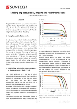
  • 1.   Fact Sheet ‐ Shading  Shading of photovoltaics, impacts and recommendations  Authors: Scott Partlin, Andreas Iliou,    Abstract  in Figure 1.    35 The goal of this document is to provide an overview  30 Current Density (mA/cm2) regarding shading of photovoltaic cells, modules and  25 arrays.  It  also  discusses  the  impact  of  shading  on  20 electrical  output,  and  recommendations  for  how  to  15 mitigate the negative effects of shading.  10   5 1. Basic photovoltaic (PV) operation  0   0 0.1 0.2 0.3 0.4 0.5 0.6 To understand how and why shading affects PV cells  Voltage (V) it is first useful to have a basic understanding of how  0% shading 50% shading 80% shading 90% shading these  cells  operate.  PV  cells  generate  electricity    when  exposed  to  direct  sunlight.  For  crystalline  Figure  1  ‐  shading  or  reducing  light  to  the  cell  has  similar  effects  on  silicon  PV  cells,  this  occurs  when  photons  (light  performance.  waves/particles) are absorbed in the silicon giving up  It shows how reducing the light to the cell (by either  their  energy  to  increase  the  energy  of  electrons  shading  or  intensity),  the  current  generated  by  that  (excited  carriers).  A  P‐N  junction  (which  is  essential  cell is similarly reduced.  in  the  operation  of  a  PV  device)  then  captures  and  Another  factor  which  can  affect  the  output  directs  these  excited  carriers  to  build  up  in  specific  performance  of  a  PV  cell  is  temperature.  As  the  regions  inside  the  cell  before  being  extracted  temperature  of  the  cell  increases  it  causes  some  of  through metal contacts and used to power electrical  the  properties  of  the  P‐N  junction  to  change.  These  devices.  changes mean the excited carriers no longer need as    much energy before being captured and directed by  2. Effects of low light, shade and temperature  the  P‐N  junction.  This  causes  a  reduction  in  the  on the operation of a single PV cell  voltage of the cell as seen in Figure 2.    The  current  generated  by  a  PV  cell  is  mostly  35 Current Density (mA/cm2) proportional to the total amount of direct light being  30 absorbed.  It  is  important  to  note  the  term  ‘direct  25 light’.  This  means  only  light  which  shines  20 unobstructed,  directly  from  the  sun  to  the  cell  is  15 absorbed and can hence generate current.  10 Similarly as the intensity of light changes throughout  5 the day, so to will the current generated by a PV cell.  0 This will mean that in the morning and evening when  0 0.1 0.2 0.3 0.4 0.5 0.6 Voltage (V) the PV cell is absorbing less light, it will generate less  25'C 45'C 65'C 100'C   current.  Figure  2  –  shows  how  increasing  cell  temperature  reduces  the  cell  The  effect  of  reducing  light  intensity  and  shading  a  voltage for the same amount of incident light.  single  cell  have  very  similar  effects.  This  is  depicted    Page 1 of 4  www.suntech‐power.com 
  • 2.   Fact Sheet ‐ Shading  3. Effects of shading on the operation of a  Obviously  the  situation  shown  in  Figure  3  would  be  multiple PV cells  unacceptable  for  energy  production,  and  module    durability. To limit the effect of shading of a cell on a  While  the  effects  of  shading  on  a  single  cell  are  module,  bypass  diodes  are  used.  A  bypass  diode  simple  to  understand,  those  effects  are  much  more  allows  a  proportion  of  the  cells  not  affected  by  complex  in  a  situation  where  multiple  PV  cells  are  shading to continue operating normally, while only a  connected together in strings. This is what occurs in  sub‐set  of  cells  all  connected  to  the  same  bypass  a PV module.  diode  operate  at  a  reduced  power.  Figure  4  shows  When  cells  are  electrically  connected  in  series  (a  the  affect  on  a  module’s  current‐voltage  series string), the combined voltage is the sum of all  performance  for  different  levels  of  shading  of  a  the cell’s voltages. In general however, the current of  single  cell,  while  Figure  5  shows  the  power‐voltage  the  combined  cells  will  be  equal  to  the  lowest  performance for the same shading conditions.  current  of  any  of  the  cells  at  that  operating  point.  5 This  means  that  some  cells  will  not  be  able  to  4 operate  at  their  preferred  maximum  power.  This  is  what is referred to by mismatch.  Current (A) 3 The  effect  of  mismatch  on  a  module  operating  2 normally is very small. However when a cell (or cells)  1 within  a  series  string  become  shaded,  their  current  0 output  is  reduced  (recall  Figure  1).  This  shaded  cell  0 10 20 30 40 50 (cells)  will  then  reduce  the  current  of  all  the  other  Voltage (V) cells.  Importantly,  the  difference  in  module  power  No Shading 1 cell 25% shaded 1 cell 50% shaded between  normal  operation  and  partial  cell  shading  1 cell 75% shaded 1 cell 100% shaded will be dissipated into the shaded cell. This would be    enough  to  destroy  a  module.  The  difference  in  Figure  4  –  current‐voltage  performance  of  a  72  cell  monocrystalline  operation of a 72 cell monocrystalline module when  module with 3 bypass diodes installed, for different levels of shading for  it is operating normally compared to when one cell is  a single cell.  50% shaded is shown in Figure 3.  5 180 180 4.5 160 160 4 140 140 120 Power (W) 3.5 120 Current (A) Power (W) 3 100 100 80 2.5 80 60 2 1.5 60 40 1 40 20 0.5 20 0 0 0 0 10 20 30 40 50 0 5 10 15 20 25 30 35 40 45 Voltage (V) Voltage (V) No Shading 1 cell 25% shaded 1 cell 50% shaded No Shading 1 cell 75% shaded 1 cell 100% shaded 1 cell 50% shaded ‐ no bypass diode   No shading (Power curve) Figure  5  ‐  power‐voltage  performance  of  a  72  cell  monocrystalline  1 cell 50% shaded (Power curve) ‐ no bypass diode module with 3 bypass diodes installed, for different levels of shading for    a single cell.  Figure  3  ‐  operation  of  a  72  cell  monocrystalline  module  when  it  is  operating normally, and with a cell 50% shaded (no by‐pass diode).        Page 2 of 4  www.suntech‐power.com 
  • 3.   Fact Sheet ‐ Shading  4. Effects of shading on the operation of a PV  5. Calculating the effect on PV array  array  performance of shading      If a PV array experiences some shading of a module  By understanding how shading affects:  (or  modules),  the  effect  on  array  power  will  be  • a single cell;  similar  to  the  effect  on  module  power  when  a  cell  • a group of cells within a module;  experiences  a  similar  shading  event.  The  only  • a group of modules in an array;  difference is total power will be affected by a lesser  it  is  possible  to  draw  some  simplified  conclusions  amount, and that affect will decrease as the number  about how array power is then affected.  of modules per string increases.    Figure  6  is  an  example  of  what  the  effect  on  array  1. As the number of modules in an array string  performance  can  be  if  a  single  module  experiences  increases, the effect on total array power,  some  shading.  It  shows  an  array  with  15  modules  for shading of a single module, will decrease.  connected  in  series.  One  of  those  modules  has    experienced  some  shading  and  covered  2. Within a module if one cell is shaded by  approximately  20%  of  the  module.  The  blue  curve  more than 50%, ALL the cells protected by  shows the current‐voltage performance of the array,  the same bypass diode will no longer  while  the  red  curve  shows  the  power‐voltage  contribute to the power of the module.  relationship.  The two peaks in the power‐voltage    curve  represent  two  local  maximum  power  3. Even small periods of shading of single cells  points.  The  greater  being  2.606  kW  and  the  can affect an entire array’s performance  lesser 2.523 kW.  output.    6. Recommendations regarding shading    Throughout  the  entire  life  of  a  PV  array,  it  is  fair  to  assume  that  every  cell  in  every  module  will  be  shaded  at  least  once  due  to  naturally  occurring,  unavoidable  environmental  factors  (eg.  dirt,  cloud,  bird droppings, etc.). It is therefore important when    designing  a  PV  array  that  care  is  taken  to  avoid  Figure 6 ‐ I‐V and P‐V curves for an array of 15 modules with one module  regular  shading  events.  Failure  to  do  so  will  void  experiencing shading of approximately 20% of the module area.  future  warranty  claims.  It  is  especially  important  in  maximising  the  overall  array  power  that,  when  the  While  this  shows  that  a  shading  event  on  a  single  array  is  operating  near  maximum  power,  regular  module in an array string can have a relatively small  shading  events  are  avoided.  This  can  also  lead  to  impact  on  total  array  power,  it  shows  there  is  a  higher  energy  production  long  term  through  negative effect and this effect can be variable. It also  improved durability of modules, where the modules  illustrates  how  regular  shading  events  can  make  are  likely  to  maintain  performance  further  above  energy prediction for an array more complex.  their warranted power.          Page 3 of 4  www.suntech‐power.com 
  • 4.   Fact Sheet ‐ Shading  7. Glossary    1. Alonso‐Garcia M.C., Ruiz J.M., Herrmann W., “Computer simulation of shading effects in photovoltaic  arrays”, Renewable Energy, 2006, vol 31, p1896‐1993.    2. Alonso‐Garcia M.C., Ruiz J.M., Chenlo F., “Experimental study of mismatch and shading effects on the I‐V  characteristic of a photovoltaic module”, Solar Energy Materials & Solar Cells, 2006, (90), p329‐340.    3. Kajihara A., Harakawa T., “Model of Photovoltaic Cell Circuits under Partial Shading”, IEEE Conference on  Industrial Technology, 2005, p866‐870    4. Meyer E., Ernest van Dyk E., “The effect of reduced shunt resistance and shadowing on photovoltaic module  performance”, Progress in Photovoltaics, 2008, vol 16, issue 2, p141‐149.    5. Quaschning V., Hanitsch R., “Numerical simulation of current‐voltage characteristics of photovoltaic systems  with shaded solar cells”, Solar Energy, 1996, vol 56, p513‐520.    6. Wysocki J., Rappaport P., “Effect of temperature on photovoltaic solar energy conversion”, Journal of  Applied Physics, 1960, vol 31, number 3, p571‐578.    Page 4 of 4  www.suntech‐power.com