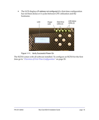
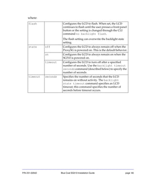
The document is the installation guide for the Blue Coat SG510 Series appliance. It describes how to unpack the SG510, install it in a rack, insert disk drives, connect cables, and power it on. It also provides an overview of initial configuration options, including using the front panel LCD, a web setup wizard, or serial console. The guide contains chapters on configuration, removing/installing drives, next steps, troubleshooting, and specifications.


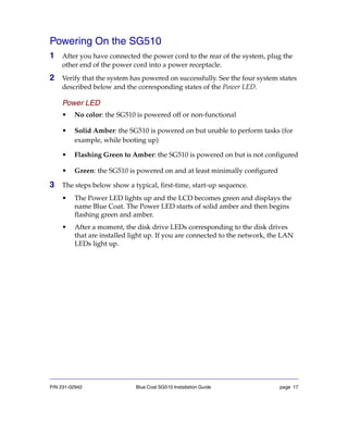


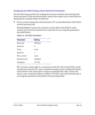
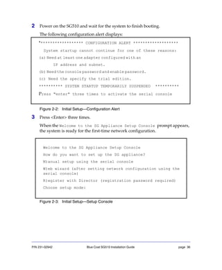
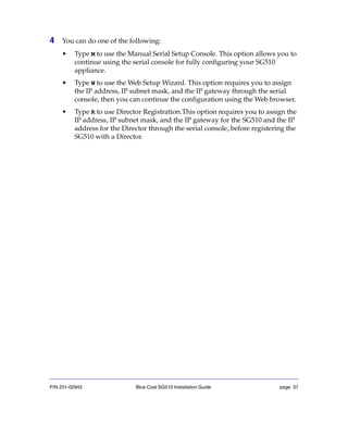
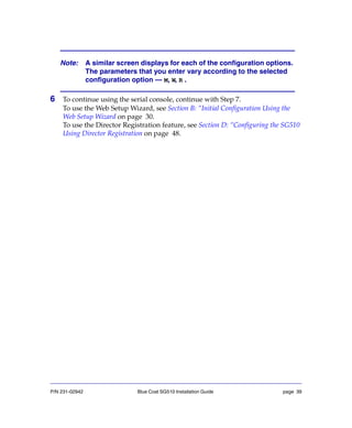
![P/N 231-02942 Blue Coat SG510 Installation Guide page 38
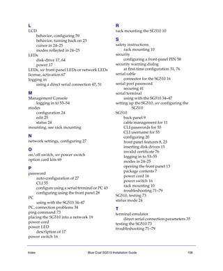
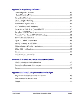
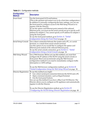
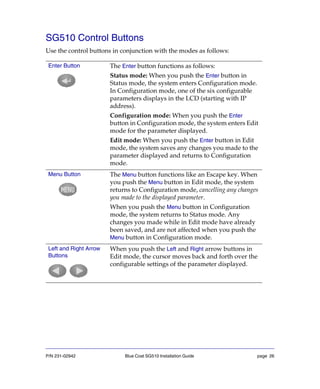
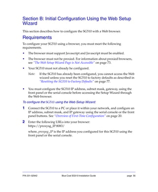
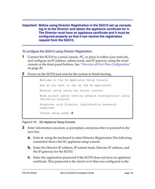
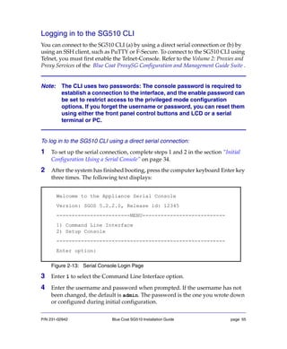
5 If you select M, the following screen displays:
Figure 2-4: Setup Console—Page One
Enter the interface number, IP address, IP subnet mask, IP gateway, and DNS
server parameters.
Note: If you enter YES, to configure a bridge, you must configure at least
one bridge port and associate a network interface with it
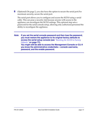
Welcome to the SG Appliance Setup Console
---------------------- (page 1 of 5)---------------------
Press<ESC>atanytimetoreturntothemainmenu
Setup mode: Manual
DIRECTIONS:
Please enter the IP addresses for the SG Appliance.
The following interface will be configured:
1. Bridge passthru-0 (no WAN link, LAN link)
IP address [0.0.0.0]: 10.0.1.246
IP subnet mask [255.255.255.0]:
IP gateway [0.0.0.0]: 10.0.1.1
DNS server [0.0.0.0]: 10.9.8.700
You have entered the following IP addresses:
IP address: 10.0.1.246
IP subnet mask: 255.255.255.0
IP gateway: 10.0.1.1
DNS server: 10.9.8.700
Would you like to change any of them? Y/N [No]](https://image.slidesharecdn.com/sg510installationguidesgos5-150215035519-conversion-gate01/85/Sg510-installation-guide_-sgos_5-2-x-38-320.jpg)
![P/N 231-02942 Blue Coat SG510 Installation Guide page 40
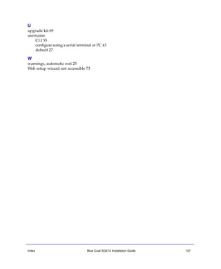
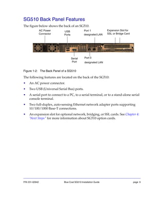
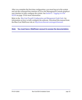
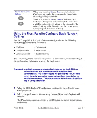
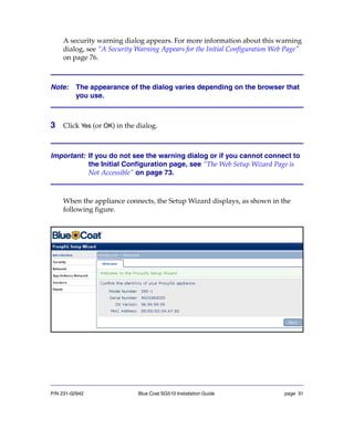
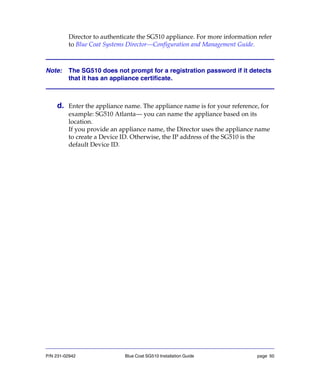
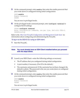
7 On page 2, enter a console username and a console and enable password. A
default username (admin) is already in place—you can change it here.
Usernames and passwords can each be from 1 to 64 characters in length.
Passwords that contain special characters (such as an exclamation point) must
be in quotes.
Figure 2-5: Setup Console—Page Two
---------------------- (page 2 of 5) ---------------------
Press <ESC> at any time to return to the main menu
DIRECTIONS:
The console username, password, and enable password are
special administrative credentials which can be used to log in
to the command line interface or web management interface.
WARNING - The console password and enable password are not
defined.
The system cannot start up until these are defined.
You must configure the console user account now.
Enter console username [admin]: admin
Enter console password: *****
Verify console password: *****
That password is easily guessed.Choose another? Y/N [Yes] No
Enter enable password: *****
Verify enable password: *****
That password is easily guessed.Choose another? Y/N [Yes] No](https://image.slidesharecdn.com/sg510installationguidesgos5-150215035519-conversion-gate01/85/Sg510-installation-guide_-sgos_5-2-x-40-320.jpg)
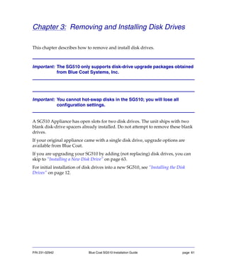
![P/N 231-02942 Blue Coat SG510 Installation Guide page 42
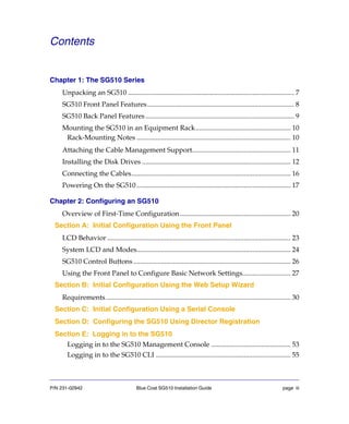
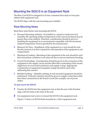
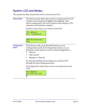
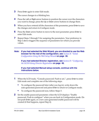
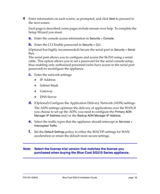
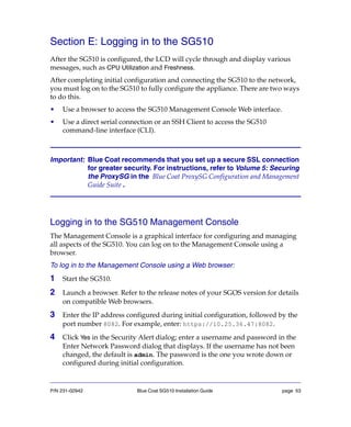
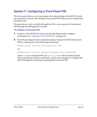
Figure 2-6: SetUp Console- Page two continued
Doyouwanttosecuretheserialport?Y/N[Yes]Yes
Enter setup password:*****
Verify setup password: *****
That password is easily guessed.
Choose another? Y/N [Yes] No
WARNING:
If you continue and enable the secure serial port it will
not be possible to enter the setup console without the
setup password. If the setup password is lost, assistance
from Blue Coat Systems will be required and all system
configuration may be lost. It is recommended that the
password be stored in a physically secure location.
Access to the CLI on the serial port will challenge for
credentials.
To enable the secure serial port, re-enter the setup
password:](https://image.slidesharecdn.com/sg510installationguidesgos5-150215035519-conversion-gate01/85/Sg510-installation-guide_-sgos_5-2-x-42-320.jpg)
![P/N 231-02942 Blue Coat SG510 Installation Guide page 43
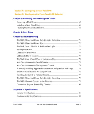
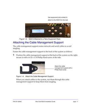
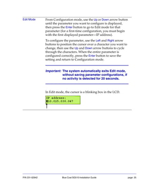
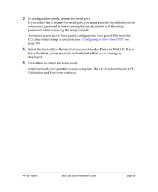
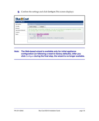
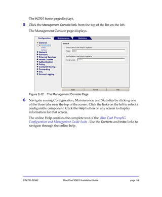
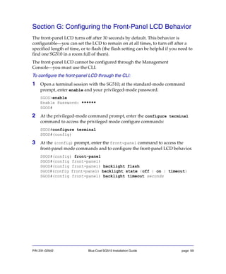
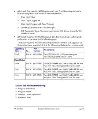
9 (Optional) On page 3, you might restrict the use of the console account to a
specific workstation. On this screen, you can add one IP address to the list of
authorized workstations that are approved to use the console account.
Additional workstations maybe configured later using the CLI or through the
Management Console.
Figure 2-7: Setup Console—Page Three
---------------------- (page 3 of 5) ---------------------
Press <ESC> at any time to return to the main menu
DIRECTIONS:
The console username and password are special. They can be used
to log in to the CLI or Web Management interface even in
circumstances where this is denied by VPM or CPL policy.
This makes the console account useful in emergencies, as a way
to log in when policy is broken, but it may also create a
security hole.
To close the security hole, we recommend that you restrict the
use of the console account to specific workstations, identified
by their IP address.
This dialog allows you to add one IP address to the list of
workstations that are authorized to use the console account.
(This same list is also used to restrict which workstations can
use SSH with RSA authentication.)
Additional workstations may be configured later from the command
line interface or the Web interface.
WARNING: The console account can currently be used to log in
from any workstation.
Would you like to restrict access to an authorized workstation?
Y/N [Yes] Yes
Authorized workstation [0.0.0.0]: 10.2.33.1](https://image.slidesharecdn.com/sg510installationguidesgos5-150215035519-conversion-gate01/85/Sg510-installation-guide_-sgos_5-2-x-43-320.jpg)

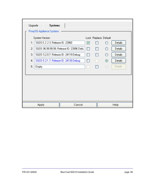
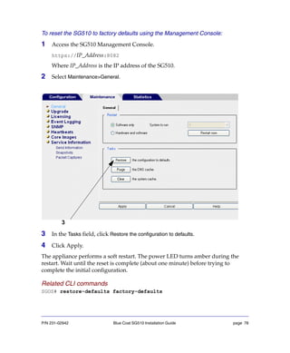
![P/N 231-02942 Blue Coat SG510 Installation Guide page 45
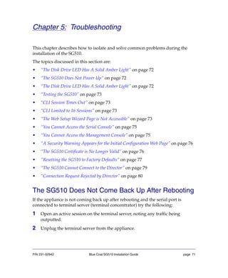
Figure 2-8: Setup Console—Page Four
---------------------- (page 4 of 5) ---------------------
Press <ESC> at any time to return to the main menu
DIRECTIONS:
An SG can have either a MACH5 Edition or Proxy Edition
license.
The SGOS MACH5 Edition is designed to optimize and secure WAN
networks being used in Application Delivery Networks (ADN).
The MACH5 Edition does not include all of the security and
control features included in the Proxy Edition. All SGOS
MACH5 Edition features, including ADN optimization, are
available in the Proxy Edition.
A new SG will run with a 60 day trial prior to installing a
license.
The SG can run either the MACH5 or Proxy Edition of SGOS
during the trial period.
It is important to note that a downgrade from Proxy Edition
to MACH5 Edition will result in a loss of configuration. As
well, some defaults differ between the MACH5 and Proxy
Edition of SGOS so settings may need to be changed after an
upgrade from MACH5 Edition to Proxy Edition.
Which edition would you like to run during the trial period?
M)ACH5 Edition
P)roxy Edition
Choose edition [Proxy]: MACH5 Edition
You have chosen MACH5 Edition as the trial edition.
Would you like to change it? Y/N [No]](https://image.slidesharecdn.com/sg510installationguidesgos5-150215035519-conversion-gate01/85/Sg510-installation-guide_-sgos_5-2-x-45-320.jpg)
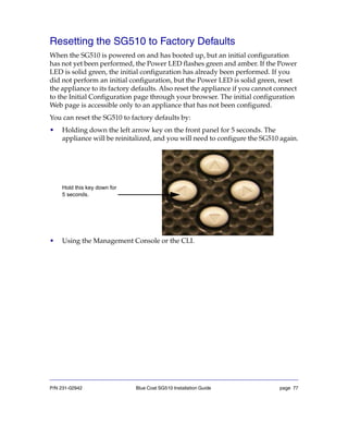
![P/N 231-02942 Blue Coat SG510 Installation Guide page 51
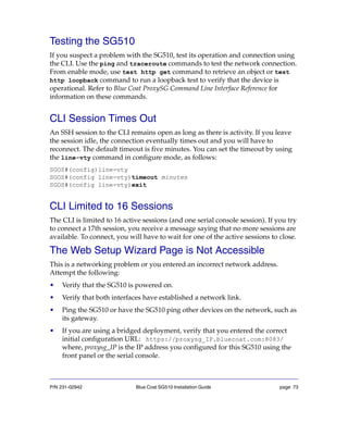
e. Verify the IP addresses.
Type Y to confirm the serial number of the Director. The SG510 is
registered.
or, Type N to abort the registration process.
f.
Figure 2-11: Screen to verify Director serial number and register with Director
4 To configure the SG510 using Director, go to the Director Management
Console or the Director CLI.
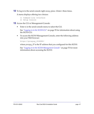
5 To log in to the serial console right away, press <Enter> three times.
A menu displays offering two choices:
1) Command Line Interface
2) Setup Console
Choose setup mode:R
IP address[0.0.0.0]:10.0.0.146
IP subnet mask [255.255.255.0]:
Director IP address [0.0.0.0]: 10.0.0.146
IP
Registration password:
Appliance name (optional):
You have entered the following IP addresses:
IP address:10.0.0.1
IP subnet mask: 255.255.255.0
Director IP: 10.0.0.146
IP gateway: 10.9.44.1
Choose setup mode:R
IP
IP
Director
IP gateway [0.0.0.0]:10.0.1.1
Registration password:
Appliance name (optional):
You have entered the following IP addresses:
IP subnet mask: 255.255.255.0
IP gateway: 10.9.44.1
Would you like to change any of them? Y/N N
Connecting to 10.0.0.146 to determine Director serial number
This can take up to 90 seconds ... please wait
Director reports serial number: 1234567899
Is that the expected serial number? Y/N Y
Connecting to 10.0.0.146 to register with Director 1234567899
Registration succeeded
Press "enter" three times to activate the serial console
b
e
d](https://image.slidesharecdn.com/sg510installationguidesgos5-150215035519-conversion-gate01/85/Sg510-installation-guide_-sgos_5-2-x-51-320.jpg)

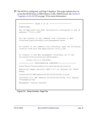
![P/N 231-02942 Blue Coat SG510 Installation Guide page 57
4 At the privileged-mode command prompt, enter configure terminal to
configure ProxySG settings:
SGOS#configure terminal
[Enter configuration commands, one per line. End with CTRL-Z.]
SGOS#(config)
Refer to the Blue Coat ProxySG Configuration and Management Guide Suite for
information about configuring and administering the ProxySG.](https://image.slidesharecdn.com/sg510installationguidesgos5-150215035519-conversion-gate01/85/Sg510-installation-guide_-sgos_5-2-x-57-320.jpg)


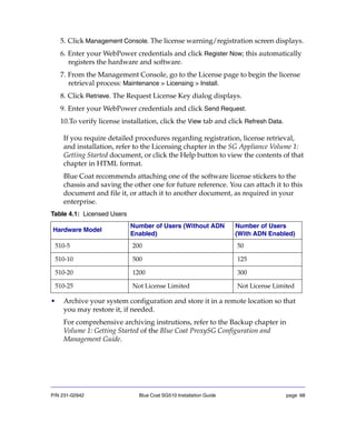


![P/N 231-02942 Blue Coat SG510 Installation Guide page 79
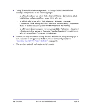
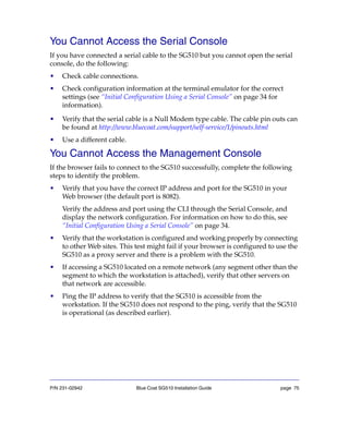
The SG510 Does Not Come Back Up After Rebooting
If the appliance is not coming back up after rebooting and the serial port is
connected to terminal server (terminal concentrator) try the following:
1 Open an active session on the terminal server, noting any traffic being
outputted.
2 Unplug the terminal server from the appliance.
The SG510 Cannot Connect to the Director
If the SG810 is unable to connect to the Director during Director Registration, the
following screen displays:
Check the following details:
• Check if you have obtained the Director appliance certificate. To obtain the
Director appliance certificate log in to the Director appliance and from the
configuration mode prompt enter:
Director (config) # ssl request-appliance-certificate ,when you have
an active internet connection.
• Validate network connection.
• Verify the IP address of the Director.
You have entered the following IP addresses:
IP address: 10.0.1.246
IP subnet mask: 255.255.255.0
Director IP: 10.0.0.1
IP gateway: 10.0.1.1
Would you like to change any of them? Y/N [No]
Connectingto10.0.0.1todetermineDirectorserialnumber
This can take up to 90 seconds ... please wait
Could not contact Director](https://image.slidesharecdn.com/sg510installationguidesgos5-150215035519-conversion-gate01/85/Sg510-installation-guide_-sgos_5-2-x-79-320.jpg)