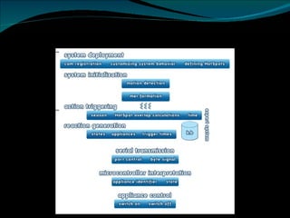
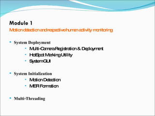
The document outlines the final presentation for the 'Imagination Kieve' project, focusing on developing an integrated system for smart control of domestic appliances through user activity monitoring. It details the architecture, three main modules (motion detection, decision-making engine, and appliance control), and the technologies used, such as .NET and C#. The project aims to enhance user convenience, energy saving, and automation in the home environment.


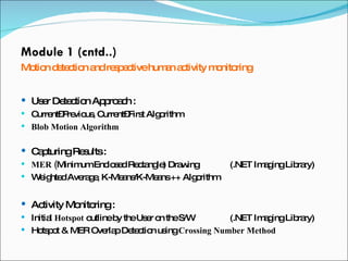
![Module 1 (cntd..) Motion detection and respective human activity monitoring Critical Difficulties Encountered– Camera Zoom [View Angle , Shadows] Camera Mounted in Room Camera Mounted in the Model](https://image.slidesharecdn.com/senior-design-project-giki-1231516903313644-1/85/Senior-Design-Project-GIKI-11-320.jpg)
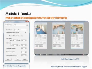
![Module 1 (cntd..) Motion detection and respective human activity monitoring Prototype Environments : Room (Hostel); Model House Image Capture Devices : CMOS Webcam; 640 x 480 pixels; Frame Rate: 30 fps; View Angle: 54 degrees Platform : .NET 2.0 based Aforge C# Framework (open source) Using the AForge.Imaging & AForge.Vision libraries [ http://code.google.com/p/aforge/ ]](https://image.slidesharecdn.com/senior-design-project-giki-1231516903313644-1/85/Senior-Design-Project-GIKI-12-320.jpg)