SlideShare a Scribd company logo
1 of 1
REMOTELY ACCESSIBLE TARGET SYSTEM Chad Ruttencutter & Peter Simon EET, CEAS, University of Cincinnati ABSTRACT Target shooting is a fun yet dangerous past time. The most dangerous and time consuming part of any long distance shooter’s day at the range is tending to their target.  The most common setup used in long distance target shooting today is a paper target located hundreds of yards from the shooter.  Even with the best optics, a target at this distance is difficult to analyze and time consuming to change.  The solution to this problem is our Remotely Accessible Target System.  This system provides the shooter a wireless connection between the target platform and a laptop computer.  A custom graphical user interface shows up-to-date information on each shot, along with scoring, and group sizes.  Not only will the platform be able to detect a shot and relay the image back to the user’s laptop, it will also hold numerous paper targets which can be advanced via a mouse click.  These features provide the shooter with the ability to remain behind the firing line and never walk down range. INTRODUCTION The Remotely Accessible Target System is a complete system which allows marksmen to enjoy a safer, more leisurely shooting experience. The main objectives the system performs areto virtually eliminate the dangerous act of walking down range to change and/or view a target. This system also saves time by eliminating the need to manually change paper targets, as well as, performing analysis and calculations in milliseconds that would take the average shooter several minutes.  TESTING APPROACH The majority of the development and testing was done in the workshop.  The camera and stepper motor were calibrated, along with the analysis software in a controlled environment.  During this process we tried to account for as many real life variables as possible. Later, field testing resulted in mixed results due to the dynamic lighting conditions.  Our physical design was then modified to accommodate for these conditions with the addition of the light shade. Figure 2: Printed circuit board layout Figure 3: Printed circuit board schematic Figure 4: Microcontroller code BUDGET EFFORT The budget below illustrates the final cost of the Remotely Accessible Target System.  This budget does not include the more that 700 hours of R&D, testing, and build time invested in the project. DESIGN REQUIREMENTS There are many required features that are included in the final design of the Remotely Accessible Target System.  The system needed to perform all tasks that would otherwise be completed by a typical long distance shooter in a portable, yet user friendly device.  These features, and many more, were accomplished using a mixture of custom hardware and software solutions. The constraints we considered were mainly from personal experiences.  We both knew what types of ranges this system would typically be used at, and what functionality would not only be practical, but would be the most useful.  From that knowledge we designed the system to have an operating distance of at least 300 yards, a bullet location resolution of less than 0.1 inches, a target size of 11.5 inches square, and a response time of less than 3 seconds. PROJECT RESULTS The final version of the Remotely Accessible Target System has exceeded most of the original design criteria.   The system’s wireless communication has been tested to 300 yards and promises closer to 500 yards of range.  The resolution has be shown to be approximately 0.045” with an accuracy of less than the intended 0.1”.  The target size is currently 11.5 inches square.  The system’s response time, which depends mostly on lighting conditions, currently averages about 1.5s per shot. This being said, the system is not yet perfect.  The shot detect sensors are currently problematic due to system noise, and a database is likely to be added in the future. TECHNICAL APPROACH This block diagram shows a high-level flow of the project.  Generally speaking, all of the events  in the top half of the flow chart are controlled using a TI MSP430f2272 microcontroller. The remainder of the flow chart is controlled using a custom C# application ran on a laptop.  The wireless link between the remote platform and the laptop computer was accomplished using an embedded Bluetooth module and USB Bluetooth dongle, both from Sena.  Not shown here is the laser gun and servos added for the Tech Expo demonstration. R.A.T.S. @ 100yds Advisor: Professor Michael Haas Figure 1: Functionality flowchart Figure 5: Field testing Figure 6: Prototyping Figure 7: Field testing

More Related Content

What's hot

blue eye technology
blue eye technologyblue eye technology
blue eye technologyRaga Deepthi
 
Conducting test on the installed computer system
Conducting test on the installed computer systemConducting test on the installed computer system
Conducting test on the installed computer systemRachel Espino
 
Hacs ( Project Presentation )
Hacs ( Project Presentation )Hacs ( Project Presentation )
Hacs ( Project Presentation )Tarun Sharma
 
Seminar blue eye
Seminar blue eyeSeminar blue eye
Seminar blue eyeanju ann
 
Wireless Surveillance Made Easy - The SmartScouter Black Ops 940
Wireless Surveillance Made Easy - The SmartScouter Black Ops 940Wireless Surveillance Made Easy - The SmartScouter Black Ops 940
Wireless Surveillance Made Easy - The SmartScouter Black Ops 940Lynn Woodruff
 

What's hot (8)

Blue eye technology
Blue eye technologyBlue eye technology
Blue eye technology
 
blue eye technology
blue eye technologyblue eye technology
blue eye technology
 
Conducting test on the installed computer system
Conducting test on the installed computer systemConducting test on the installed computer system
Conducting test on the installed computer system
 
Hacs ( Project Presentation )
Hacs ( Project Presentation )Hacs ( Project Presentation )
Hacs ( Project Presentation )
 
Blue Eyes Technology
Blue Eyes TechnologyBlue Eyes Technology
Blue Eyes Technology
 
Seminar blue eye
Seminar blue eyeSeminar blue eye
Seminar blue eye
 
Wireless Surveillance Made Easy - The SmartScouter Black Ops 940
Wireless Surveillance Made Easy - The SmartScouter Black Ops 940Wireless Surveillance Made Easy - The SmartScouter Black Ops 940
Wireless Surveillance Made Easy - The SmartScouter Black Ops 940
 
Blue eyes technology
Blue eyes technologyBlue eyes technology
Blue eyes technology
 

Similar to Remotely Access Target System Under 40 Characters

Blue-eyes-technology-ppt.pptx
Blue-eyes-technology-ppt.pptxBlue-eyes-technology-ppt.pptx
Blue-eyes-technology-ppt.pptxPranita602627
 
Blue-eyes-technology-ppt.pptx
Blue-eyes-technology-ppt.pptxBlue-eyes-technology-ppt.pptx
Blue-eyes-technology-ppt.pptxPranita602627
 
IRJET- Smart Switch Board Compatible with Google Assistance along with Fa...
IRJET-  	  Smart Switch Board Compatible with Google Assistance along with Fa...IRJET-  	  Smart Switch Board Compatible with Google Assistance along with Fa...
IRJET- Smart Switch Board Compatible with Google Assistance along with Fa...IRJET Journal
 
Blue eyes technology ppt
Blue eyes technology pptBlue eyes technology ppt
Blue eyes technology pptijaranjani
 
Blue-eyes-technology-ppt.pptx
Blue-eyes-technology-ppt.pptxBlue-eyes-technology-ppt.pptx
Blue-eyes-technology-ppt.pptxSHYAMSUNDAR334390
 
ARDUINO EMBEDDED SYSTEM
ARDUINO EMBEDDED SYSTEMARDUINO EMBEDDED SYSTEM
ARDUINO EMBEDDED SYSTEMVishal GARG
 
My thesis work on Cognitive automation of Electric appliances
My thesis work on Cognitive automation of Electric appliancesMy thesis work on Cognitive automation of Electric appliances
My thesis work on Cognitive automation of Electric appliancesAkhil Reddy Rondla
 
IRJET - Contactless Biometric Security System using Finger Knuckle Patterns
IRJET -  	  Contactless Biometric Security System using Finger Knuckle PatternsIRJET -  	  Contactless Biometric Security System using Finger Knuckle Patterns
IRJET - Contactless Biometric Security System using Finger Knuckle PatternsIRJET Journal
 
Smart security system for sensitive area by using image processing
Smart security system for sensitive area by using   image processingSmart security system for sensitive area by using   image processing
Smart security system for sensitive area by using image processingMandar Pathrikar
 
DISTRIBUTED SYSTEM FOR 3D REMOTE MONITORING USING KINECT DEPTH CAMERAS
DISTRIBUTED SYSTEM FOR 3D REMOTE MONITORING USING KINECT DEPTH CAMERASDISTRIBUTED SYSTEM FOR 3D REMOTE MONITORING USING KINECT DEPTH CAMERAS
DISTRIBUTED SYSTEM FOR 3D REMOTE MONITORING USING KINECT DEPTH CAMERAScscpconf
 
Controlling Home Appliances by using Universal Remote Control System (IoT and...
Controlling Home Appliances by using Universal Remote Control System (IoT and...Controlling Home Appliances by using Universal Remote Control System (IoT and...
Controlling Home Appliances by using Universal Remote Control System (IoT and...IRJET Journal
 
Background differencing algorithm for moving object detection using system ge...
Background differencing algorithm for moving object detection using system ge...Background differencing algorithm for moving object detection using system ge...
Background differencing algorithm for moving object detection using system ge...eSAT Publishing House
 

Similar to Remotely Access Target System Under 40 Characters (20)

Src 147
Src 147Src 147
Src 147
 
Blue eye technology
Blue eye technology Blue eye technology
Blue eye technology
 
Blue-eyes-technology-ppt.pptx
Blue-eyes-technology-ppt.pptxBlue-eyes-technology-ppt.pptx
Blue-eyes-technology-ppt.pptx
 
Blue-eyes-technology-ppt.pptx
Blue-eyes-technology-ppt.pptxBlue-eyes-technology-ppt.pptx
Blue-eyes-technology-ppt.pptx
 
IRJET- Smart Switch Board Compatible with Google Assistance along with Fa...
IRJET-  	  Smart Switch Board Compatible with Google Assistance along with Fa...IRJET-  	  Smart Switch Board Compatible with Google Assistance along with Fa...
IRJET- Smart Switch Board Compatible with Google Assistance along with Fa...
 
Blue eyes technology ppt
Blue eyes technology pptBlue eyes technology ppt
Blue eyes technology ppt
 
Blue-eyes-technology-ppt.pptx
Blue-eyes-technology-ppt.pptxBlue-eyes-technology-ppt.pptx
Blue-eyes-technology-ppt.pptx
 
Blue eyes technology
Blue eyes technologyBlue eyes technology
Blue eyes technology
 
ARDUINO EMBEDDED SYSTEM
ARDUINO EMBEDDED SYSTEMARDUINO EMBEDDED SYSTEM
ARDUINO EMBEDDED SYSTEM
 
My thesis work on Cognitive automation of Electric appliances
My thesis work on Cognitive automation of Electric appliancesMy thesis work on Cognitive automation of Electric appliances
My thesis work on Cognitive automation of Electric appliances
 
IRJET - Contactless Biometric Security System using Finger Knuckle Patterns
IRJET -  	  Contactless Biometric Security System using Finger Knuckle PatternsIRJET -  	  Contactless Biometric Security System using Finger Knuckle Patterns
IRJET - Contactless Biometric Security System using Finger Knuckle Patterns
 
Smart security system for sensitive area by using image processing
Smart security system for sensitive area by using   image processingSmart security system for sensitive area by using   image processing
Smart security system for sensitive area by using image processing
 
DISTRIBUTED SYSTEM FOR 3D REMOTE MONITORING USING KINECT DEPTH CAMERAS
DISTRIBUTED SYSTEM FOR 3D REMOTE MONITORING USING KINECT DEPTH CAMERASDISTRIBUTED SYSTEM FOR 3D REMOTE MONITORING USING KINECT DEPTH CAMERAS
DISTRIBUTED SYSTEM FOR 3D REMOTE MONITORING USING KINECT DEPTH CAMERAS
 
Blue eye technology
Blue eye technologyBlue eye technology
Blue eye technology
 
Ayesha Sharief
Ayesha ShariefAyesha Sharief
Ayesha Sharief
 
Alcohol report
Alcohol reportAlcohol report
Alcohol report
 
Dualis Contour Brochure
Dualis Contour BrochureDualis Contour Brochure
Dualis Contour Brochure
 
embedded systems
embedded systemsembedded systems
embedded systems
 
Controlling Home Appliances by using Universal Remote Control System (IoT and...
Controlling Home Appliances by using Universal Remote Control System (IoT and...Controlling Home Appliances by using Universal Remote Control System (IoT and...
Controlling Home Appliances by using Universal Remote Control System (IoT and...
 
Background differencing algorithm for moving object detection using system ge...
Background differencing algorithm for moving object detection using system ge...Background differencing algorithm for moving object detection using system ge...
Background differencing algorithm for moving object detection using system ge...
 

Remotely Access Target System Under 40 Characters

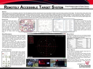
  • 1. REMOTELY ACCESSIBLE TARGET SYSTEM Chad Ruttencutter & Peter Simon EET, CEAS, University of Cincinnati ABSTRACT Target shooting is a fun yet dangerous past time. The most dangerous and time consuming part of any long distance shooter’s day at the range is tending to their target. The most common setup used in long distance target shooting today is a paper target located hundreds of yards from the shooter. Even with the best optics, a target at this distance is difficult to analyze and time consuming to change. The solution to this problem is our Remotely Accessible Target System. This system provides the shooter a wireless connection between the target platform and a laptop computer. A custom graphical user interface shows up-to-date information on each shot, along with scoring, and group sizes. Not only will the platform be able to detect a shot and relay the image back to the user’s laptop, it will also hold numerous paper targets which can be advanced via a mouse click. These features provide the shooter with the ability to remain behind the firing line and never walk down range. INTRODUCTION The Remotely Accessible Target System is a complete system which allows marksmen to enjoy a safer, more leisurely shooting experience. The main objectives the system performs areto virtually eliminate the dangerous act of walking down range to change and/or view a target. This system also saves time by eliminating the need to manually change paper targets, as well as, performing analysis and calculations in milliseconds that would take the average shooter several minutes. TESTING APPROACH The majority of the development and testing was done in the workshop. The camera and stepper motor were calibrated, along with the analysis software in a controlled environment. During this process we tried to account for as many real life variables as possible. Later, field testing resulted in mixed results due to the dynamic lighting conditions. Our physical design was then modified to accommodate for these conditions with the addition of the light shade. Figure 2: Printed circuit board layout Figure 3: Printed circuit board schematic Figure 4: Microcontroller code BUDGET EFFORT The budget below illustrates the final cost of the Remotely Accessible Target System. This budget does not include the more that 700 hours of R&D, testing, and build time invested in the project. DESIGN REQUIREMENTS There are many required features that are included in the final design of the Remotely Accessible Target System. The system needed to perform all tasks that would otherwise be completed by a typical long distance shooter in a portable, yet user friendly device. These features, and many more, were accomplished using a mixture of custom hardware and software solutions. The constraints we considered were mainly from personal experiences. We both knew what types of ranges this system would typically be used at, and what functionality would not only be practical, but would be the most useful. From that knowledge we designed the system to have an operating distance of at least 300 yards, a bullet location resolution of less than 0.1 inches, a target size of 11.5 inches square, and a response time of less than 3 seconds. PROJECT RESULTS The final version of the Remotely Accessible Target System has exceeded most of the original design criteria. The system’s wireless communication has been tested to 300 yards and promises closer to 500 yards of range. The resolution has be shown to be approximately 0.045” with an accuracy of less than the intended 0.1”. The target size is currently 11.5 inches square. The system’s response time, which depends mostly on lighting conditions, currently averages about 1.5s per shot. This being said, the system is not yet perfect. The shot detect sensors are currently problematic due to system noise, and a database is likely to be added in the future. TECHNICAL APPROACH This block diagram shows a high-level flow of the project. Generally speaking, all of the events in the top half of the flow chart are controlled using a TI MSP430f2272 microcontroller. The remainder of the flow chart is controlled using a custom C# application ran on a laptop. The wireless link between the remote platform and the laptop computer was accomplished using an embedded Bluetooth module and USB Bluetooth dongle, both from Sena. Not shown here is the laser gun and servos added for the Tech Expo demonstration. R.A.T.S. @ 100yds Advisor: Professor Michael Haas Figure 1: Functionality flowchart Figure 5: Field testing Figure 6: Prototyping Figure 7: Field testing