This document summarizes research on manipulating compound microspheres using optical forces. Key points:
1) Optical forces can trap and tether two microspheres together by generating a point node of zero field (PNJ) between them.
2) Simulations show the microspheres move towards equilibrium positions determined by the refractive indices and optical forces.
3) Adding a third microsphere above the first two can also trap it, with an alternating refractive index arrangement providing strongest trapping. The total electric field shows another weaker PNJ forms above the top microsphere.
4) The optical forces that trap the microspheres depend nonlinearly on the refractive indices, preventing simple scaling to larger
![6
b)
−3 −1 1 3
−6
−4
−2
0
2
4
6
c)
−3 −1 1 3
−6
−4
−2
0
2
4
6
2 3 4 5 6
0
0.01
0.02
0.03
zc
(µm)
<Sext
>⋅z
z=−4 µm
z=−3.6 µm
z=−3.2 µm
z=−2.8 µm
z=−2.4 µm
z=−2.0 µm
z=−1.6 µm
z=−1.2 µm
z=−0.8 µm
z=−0.4 µm
FIG. 4. Total electric field |E| (i.e. incident + scattered +
internal) and the time-averaged extinction Poynting vector
Sext
· ˆz shown for a single sphere system centered at z1 =
−3.5µm with radius R1 = 1.5µm and refractive index η1 =
1.59 in (a) and (b), respectively. Although PNJ behaviour
is observed in both plots, it is harder to discern which part
of the field is generated by the incident and scattered in (a).
A problem that is avoided by capturing only the radiative
interference in (b). Translating the sphere along the z-axis at
discrete intervals from z1 = −4µm to z1 = −0.4µm in steps
of 0.4µm and plotting the time-averaged extinction Poynting
vector along the z-axis above the sphere, we obtain the plots
in (c). The PNJ is best observed when the sphere is held
below the focal point.
We highlight the total electric field, |E|, of the (1.7143,
1.5796) and (1.6918, 1.5796) refractive index pairs in Fig.
(7a) further showing that a tethered PNJ is developed.
The results so far indicate a trapping ability and PNJ
tether ability for compound spheres. Obviously, it is far
more practical to consider a system where the compound
condition is removed, i.e. the two spheres are free to
move. To validate the trapping and PNJ generation in
this free-to-move scenario we should consider a dynamic
system that consists of light-matter interaction and hy-
drodynamic forces over time. The forces acting on the
spheres due to light-matter interaction can be calculated
at each time step with the iterative procedure described
above. The forces on the spheres due to hydrodynamic
interactions, i.e. between the fluid and the spheres, can
be calculated using the Method of Reflections (MoR) [43]
−4 −3 −2 −1 0 1 2 3 4
−0.3
−0.2
−0.1
0
0.1
0.2
0.3
0.4
zc
(µm)
Q
z
#1
#2
z
c
(1.59, 1.59)
(1.7143, 1.602)
(1.7143, 1.5796)
(1.6918, 1.5796)
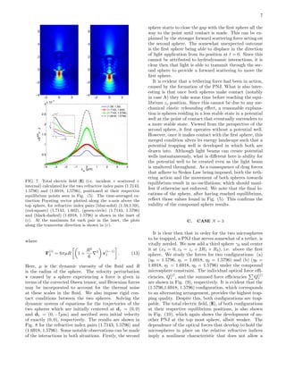
FIG. 5. Optical force efficiencies Q
(j)
z (zc) of com-
pound microspheres for refractive index pairs (η1, η2): (blue-
solid) (1.59,1.59), (red-square) (1.7143, 1.602), (green-circle)
(1.7143, 1.5796) and (black-dashed) (1.6918, 1.5796). The
centers of the spheres are set by (x1,2 = 0, z1,2 = zc ± R1,2),
where zc is the contact point of the compound spheres as
shown in the inset. The radius of the microspheres are fixed
such that R1 ≡ R2 = 1.5µm and are illuminated with an
x-polarized Gaussian beam focused at (x = 0, z = 0) with a
wavelength of λ = 1.064µm. A zero-crossing is observed for all
pairs except the (1.59, 1.59) pair, which has been previously
to exhibit particle exchange behaviour when the compound
condition is relaxed [15].
−4 −3 −2 −1 0 1 2 3 4
−0.3
−0.2
−0.1
0
0.1
0.2
0.3
0.4
zc
(µm)
Qz
(1)
M=0
M=1
M=2
M=3
−4 −2 0 2 4
−0.5
0
0.5
1
Qz
(2)
FIG. 6. Optical force efficiencies, Q
(1)
z and Q
(2)
z (inset), de-
composed using Debye series analysis, such that the bottom
sphere is represented with the transition matrix TS
M under
the condition that p = M and S = 0, and the top sphere is
represented using the full Mie coefficients. Evidently, Q
(2)
z is
dominated mostly by the first-order of transmission M = 1,
with later components providing only a minute change. In the
case of Q
(1)
z , we observe that the first-order of transmission
(PNJ) from the bottom sphere and the first-order of internal
reflection (evanescent) contributes a significant amount to the
top sphere.](https://image.slidesharecdn.com/d0452430-08d9-4569-822d-f8411c29a430-160616024139/85/selection-1-1-320.jpg)