Scaffold Training Institute
CompetentPerson Manual
Section 04:
System Type Scaffold
Note: The slides in this
presentation will match
the pictures in Section
Four of the manual.
6.
Connector
Device
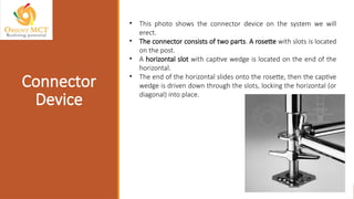
• This photoshows the connector device on the system we will
erect.
• The connector consists of two parts. A rosette with slots is located
on the post.
• A horizontal slot with captive wedge is located on the end of the
horizontal.
• The end of the horizontal slides onto the rosette, then the captive
wedge is driven down through the slots, locking the horizontal (or
diagonal) into place.
7.
Base Plates
and Screw
Jacks
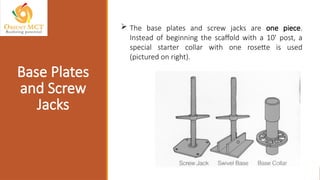
The base plates and screw jacks are one piece.
Instead of beginning the scaffold with a 10' post, a
special starter collar with one rosette is used
(pictured on right).
8.
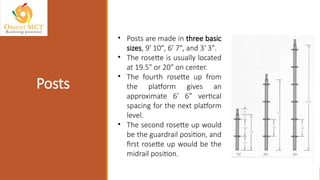
• Posts aremade in three basic
sizes, 9' 10", 6' 7", and 3' 3".
• The rosette is usually located
at 19.5" or 20" on center.
• The fourth rosette up from
the platform gives an
approximate 6’ 6” vertical
spacing for the next platform
level.
• The second rosette up would
be the guardrail position, and
first rosette up would be the
midrail position.
Posts
9.
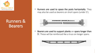
• Runners areused to space the posts horizontally. They
may also be used as bearers on short spans (under 5').
• Bearers are used to support planks on spans longer than
5'. These will be reinforced like a truss on longer spans.
Runners &
Bearers
10.
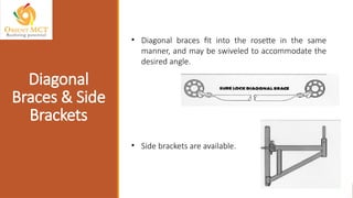
• Diagonal bracesfit into the rosette in the same
manner, and may be swiveled to accommodate the
desired angle.
• Side brackets are available.
Diagonal
Braces & Side
Brackets
11.
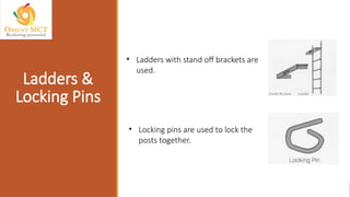
• Ladders withstand off brackets are
used.
• Locking pins are used to lock the
posts together.
Ladders &
Locking Pins
12.
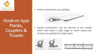
• Hook-on typeplanks are available.
• Special components may be secured to the rosette
which have either a right angle or swivel clamp end.
Trusses are available for longer spans.
Hook-on type
Planks,
Couplers &
Trusses
• First, layout the mudsills at approximate centers and place
base jacks on them.
• With system scaffold, the length and width are determined
by the fixed length of the horizontals chosen. Most system
scaffolds offer horizontals in 3', 4', 5’, 6', 7', 8', & 10'.
Place Mudsills
& Base Jacks
16.
• Place thestarter collars on the jacks. Connect the runners
and bearers to the rosette on the starter collar.
• This is done by sliding the slot on the end of the horizontal
onto the rosette, the driving the wedge down through the
slot in the rosette.
Place Starter
Collars on the
Jacks
17.
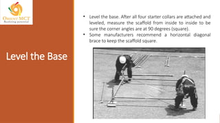
• Level thebase. After all four starter collars are attached and
leveled, measure the scaffold from inside to inside to be
sure the corner angles are at 90 degrees (square).
• Some manufacturers recommend a horizontal diagonal
brace to keep the scaffold square.
Level the Base
18.
• Set themain posts into the starter collars.
Insert Post
(Standards)
19.
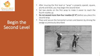
• After insuringthe first level or "wrap" is properly spaced, square,
plumb and level, you may begin the second level.
• Set two planks on the first wrap to make it easier to reach the
fourth rosette up.
• Do not exceed more than four rosettes (6' 6") before you place this
second wrap.
• Place and secure the horizontal runners and bearers by driving the
wedge as previously described.
Begin the
Second Level
20.
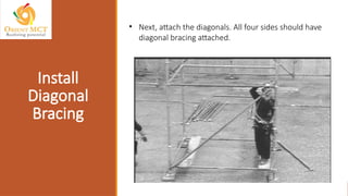
• Next, attachthe diagonals. All four sides should have
diagonal bracing attached.
Install
Diagonal
Bracing
21.
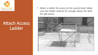
• Attach aladder for access to the second level. Make
sure the ladder extends far enough above the deck
for safe access.
Attach Access
Ladder
22.
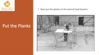
• Next putthe planks on the second level bearers.
Put the Planks
23.
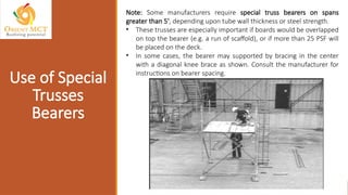
Note: Some manufacturersrequire special truss bearers on spans
greater than 5', depending upon tube wall thickness or steel strength.
• These trusses are especially important if boards would be overlapped
on top the bearer (e.g. a run of scaffold), or if more than 25 PSF will
be placed on the deck.
• In some cases, the bearer may supported by bracing in the center
with a diagonal knee brace as shown. Consult the manufacturer for
instructions on bearer spacing.
Use of Special
Trusses
Bearers
24.
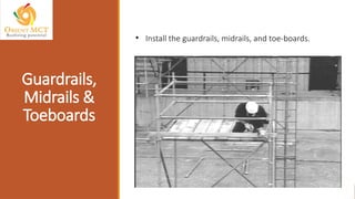
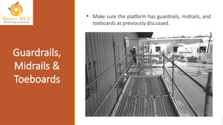
• Install theguardrails, midrails, and toe-boards.
Guardrails,
Midrails &
Toeboards
25.
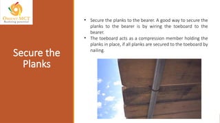
• Secure theplanks to the bearer. A good way to secure the
planks to the bearer is by wiring the toeboard to the
bearer.
• The toeboard acts as a compression member holding the
planks in place, if all planks are secured to the toeboard by
nailing.
Secure the
Planks
26.
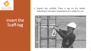
• Inspect thescaffold. Place a tag on the ladder
indicating it has been inspected and is ready for use.
Insert the
Scaff-tag
27.
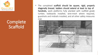
• The completedscaffold should be square, rigid, properly
diagonally braced, ladders should extend at least to top of
handrails, work platforms fully planked with scaffold grade
lumber, toeboards installed, wire-mesh where required,
guardrails and midrails installed, and all other safety measures
met.
Complete
Scaffold
28.
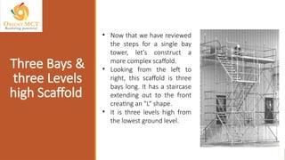
• Now thatwe have reviewed
the steps for a single bay
tower, let's construct a
more complex scaffold.
• Looking from the left to
right, this scaffold is three
bays long. It has a staircase
extending out to the front
creating an "L“ shape.
• It is three levels high from
the lowest ground level.
Three Bays &
three Levels
high Scaffold
29.
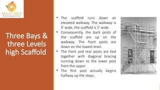
• The scaffoldruns down an
elevated walkway. The walkway is
4' wide, the scaffold is 5' wide.
• Consequently, the back posts of
the scaffold are up on the
walkway. The front posts are
down on the lowest level.
• The front and rear posts are tied
together with diagonal bracing
running down to the lower post
from the upper.
• The first post actually begins
halfway up the steps.
Three Bays &
three Levels
high Scaffold
30.
• Looking fromright to left, we see the three bays with staircase.
• There is one working level on top. The bay with the staircase is
actually sub-divided in front into two 3' 6" bays to accommodate
the stair risers. Now let's begin.
Three Bays &
three Levels
high Scaffold
• After thepre-job planning is done, lay out the mudsills,
base jacks, and starter collars at approximate location.
• In this picture the "L" shaped staircase bay is being set. It is
two parallel 3' 6" by 7' bays.
• The jacks further down at the base of the walkway will be
the front posts of the scaffold. The rear posts are laid out
on the upper walkway.
Place the
Mudsills, Base
Jacks &
Starter Collars
33.
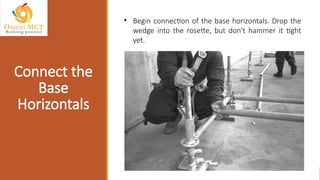
• Begin connectionof the base horizontals. Drop the
wedge into the rosette, but don't hammer it tight
yet.
Connect the
Base
Horizontals
34.
• Start atthe high end and use the screw jacks to level
all base horizontals.
Level all Base
Horizontals
35.
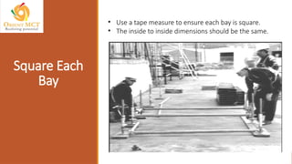
• Use atape measure to ensure each bay is square.
• The inside to inside dimensions should be the same.
Square Each
Bay
36.
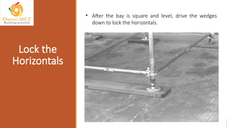
• After thebay is square and level, drive the wedges
down to lock the horizontals.
Lock the
Horizontals
37.
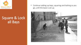
• Continue settingup bays, squaring and locking as you
go, until the base is set up.
Square & Lock
all Bays
38.
• Now wecan set the posts into the starter collars.
• Pick up the post carefully, lower it over the screw
jack, and drop it into the collar.
Set the Posts
Into the
Starter Collars
39.
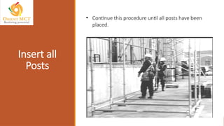
• Continue thisprocedure until all posts have been
placed.
Insert all
Posts
40.
• Install secondlevel runners and bearers no higher
than the fourth level of ring sets.
Install the
Second Level
Runners &
Bearers
41.
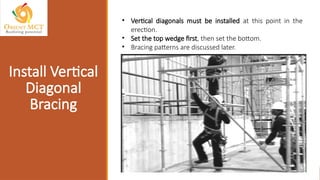
• Vertical diagonalsmust be installed at this point in the
erection.
• Set the top wedge first, then set the bottom.
• Bracing patterns are discussed later.
Install Vertical
Diagonal
Bracing
42.
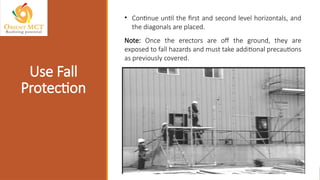
• Continue untilthe first and second level horizontals, and
the diagonals are placed.
Note: Once the erectors are off the ground, they are
exposed to fall hazards and must take additional precautions
as previously covered.
Use Fall
Protection
43.
Note: 1926.451(g)(2) requiresthe erectors to have fall
protection if it is feasible to provide and does not create
a greater hazard. Most manufacturers have issued
warnings against using the scaffold itself as a anchorage
point for personal fall arrest systems. Consult your
company safety department for company policy.
Fall
Protection
44.
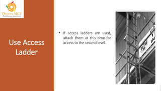
• If accessladders are used,
attach them at this time for
access to the second level.
Use Access
Ladder
45.
• Install additionalvertical post in the same manner as the
previous post installation to increase scaffold height.
Install
Additional
Post
46.
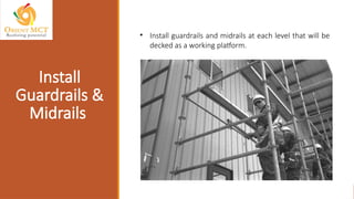
• Install guardrailsand midrails at each level that will be
decked as a working platform.
Install
Guardrails &
Midrails
47.
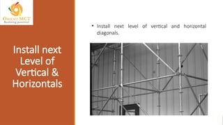
• Install nextlevel of vertical and horizontal
diagonals.
Install next
Level of
Vertical &
Horizontals
48.
• Continue toinstall horizontals. Be sure to lock all
the wedges in place as you go.
Lock all the
Wedges
49.
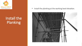
• Install theplanking at the working level elevation.
Install the
Planking
50.
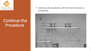
• Continue allprocedures until the main structure is
completed.
Continue the
Procedure
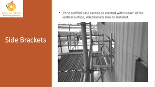
Side Brackets
• Ifthe scaffold base cannot be erected within reach of the
vertical surface, side brackets may be installed.
53.
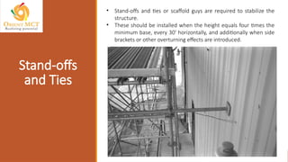
Stand-offs
and Ties
• Stand-offsand ties or scaffold guys are required to stabilize the
structure.
• These should be installed when the height equals four times the
minimum base, every 30' horizontally, and additionally when side
brackets or other overturning effects are introduced.
54.
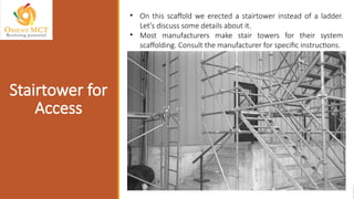
Stairtower for
Access
• Onthis scaffold we erected a stairtower instead of a ladder.
Let's discuss some details about it.
• Most manufacturers make stair towers for their system
scaffolding. Consult the manufacturer for specific instructions.
55.
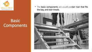
• The basiccomponents are usually a stair riser that fits
the bay, and stair treads.
Basic
Components
56.
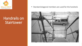
• Standard diagonalmembers are used for the handrails
Handrails on
Stairtower
57.
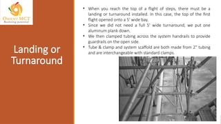
• When youreach the top of a flight of steps, there must be a
landing or turnaround installed. In this case, the top of the first
flight opened onto a 5' wide bay.
• Since we did not need a full 5' wide turnaround, we put one
aluminum plank down.
• We then clamped tubing across the system handrails to provide
guardrails on the open side.
• Tube & clamp and system scaffold are both made from 2" tubing
and are interchangeable with standard clamps.
Landing or
Turnaround
58.
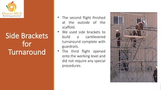
• The secondflight finished
at the outside of the
scaffold.
• We used side brackets to
build a cantilevered
turnaround complete with
guardrails.
• The third flight opened
onto the working level and
did not require any special
procedures.
Side Brackets
for
Turnaround
59.
Diagonal
Bracing
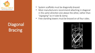
• System scaffoldsmust be diagonally braced.
• Most manufacturers recommend attaching in diagonal
in the same direction one above the other, rather than
"zigzaging“ as in tube & clamp.
• Free standing towers must be braced on all four sides.
60.
• Circular scaffoldstructures must be diagonally
braced every other bay.
• These braces should oppose each other. (Follow the
manufacturers' instruction, some may differ).
Diagonal
Bracing
61.
Vertical
Diagonal
Bracing
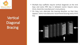
• Multiple bayscaffolds require vertical diagonals at the end
bays and every fifth bay in between (some require every
third, check the manufacturer's instructions).
• On long runs alternate the bracing direction so that they
oppose. Some manufacturers recommend bracing every third
bay.
62.
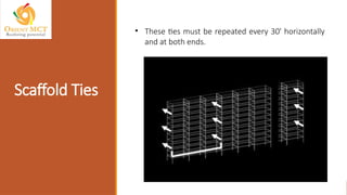
Scaffold Ties
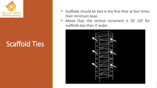
• Scaffoldsshould be tied in the first time at four times
their minimum base.
• Above that, the vertical increment is 26’ (20' for
scaffolds less than 3' wide) .
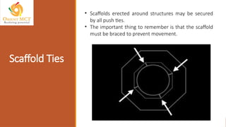
Scaffold Ties
• Scaffoldserected around structures may be secured
by all push ties.
• The important thing to remember is that the scaffold
must be braced to prevent movement.
65.
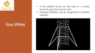
Guy Wires
• Ifthe scaffold cannot be tied back to a nearby
structure, guy wires may be used.
• All guyed scaffolds must be designed by a qualified
engineer.
66.
Scaffold Ties
• Somemanufacturers recommend horizontal diagonals at the tie
point locations.
• System is different than tube & clamp in one important regard.
• Most right angle clamps apply the same rigidity laterally.
• However, system scaffolds vary widely in the lateral strength of
the connection.
• Some are extremely rigid laterally, others are not.
• That is why it is so important to follow the manufacturer's
instructions for bracing, tieing, and guying.
67.
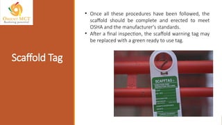
Scaffold Tag
• Onceall these procedures have been followed, the
scaffold should be complete and erected to meet
OSHA and the manufacturer's standards.
• After a final inspection, the scaffold warning tag may
be replaced with a green ready to use tag.
68.
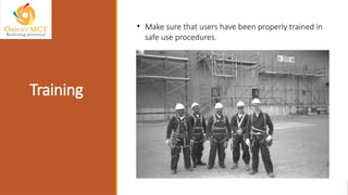
Training
• Make surethat users have been properly trained in
safe use procedures.
69.
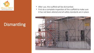
Dismantling
• After use,the scaffold will be dismantled.
• First do a complete inspection of the scaffold to make sure
it has not been altered and all safety standards are in place.
70.
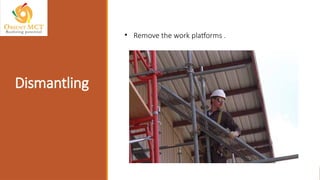
Dismantling
• Dismantling systemscaffolding is more or less just the
reverse of erection.
• Start at the top by dismantling the guardrails. Remove and
lower each piece as you unsecure it.
• Do not leave an unsecured piece in place, even for a
moment.
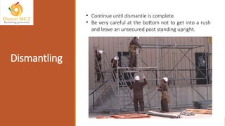
Dismantling
• Continue untildismantle is complete.
• Be very careful at the bottom not to get into a rush
and leave an unsecured post standing upright.
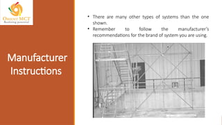
Manufacturer
Instructions
• There aremany other types of systems than the one
shown.
• Remember to follow the manufacturer’s
recommendations for the brand of system you are using.
#1 Various types of businesses commonly conduct hazard analysis and risk assessments. Both processes inform businesses of the potential consequences of particular actions and help prepare them for many kinds of situations.
#2 Before moving further quick familiarization with ground rules:
If you hear a fire alarm, follow the emergency procedures and protocols at your workplace.
Use the chat feature or unmute and discuss to make this session interactive.
There will be a Q&A and discussion in the last 15 to 20 minutes of this session
#3 OrientMCT, is a leading Technology, Training and Management Consulting firm, established in 2013. We have various national and international accreditations and partnerships. We are working with leading national and international clients, and helping people and companies to achieve their objectives, targets, regulatory requirements and best practices in health and safety.
We are OSHAD Grade A consulting company. We are registered vendor with top government and private entities and having accreditations and partnership with national and international bodies.
We have large base of clients in all sectors which includes, construction, manufacturing, energy, healthcare, schools and universities, transport, oil and gas and other process industries.
We are iso 9001:2015;4001:2015, 45001:2018; 27001:2013(Information Security MS); 22301:2019 (Business Continuity MS) and 29993:2017 (Learning Services for Education and Training)
#4 We are in different domains,.
You are our esteemed and regular clients. Thank you again!