The daily report summarizes maintenance and repair work done on an offshore oil rig between December 22nd and January 8th. Key activities included:
- Rebuilding lower choke valves and performing maintenance on a transporter.
- Opening bonnets and performing inspections on various ram blocks. Shuttle and seals were replaced.
- Cleaning and dimensional checks of ram cavities. NDT inspections were conducted.
- Troubleshooting electrical issues with a BOP hydraulic power unit mix tank. Surface accumulators were pre-charged.
- Replacing seals in a lower isolation valve and commissioning a ROMAR control panel. Welding alterations were started on a dynamic seal assembly.
-
This project log summarizes work done replacing a 200-foot sewer section under a parking lot using trenchless technology. A new 8-inch HDPE pipe was pulled through using an air-powered impactor head. Special conditions required testing a new impactor head design. Various tools were used including a hydraulic ram and backhoe. The impactor became stuck inside the bursting head and efforts to remove it by reversing the hammer or applying anti-seize were unsuccessful.
For over the years SAP parts have been successfully fulfilled the need of efficient and high end
application mechanical seals to various industry segments.
This document contains information about Eng. El Sayed Amer, a petroleum engineer who has worked for Weatherford Drilling International and as a process and production engineer for SUCO and RWE DEA. It discusses production packers, which are subsurface tools used to provide a seal between the tubing and casing. Production packers can protect the casing from corrosion, provide better well control, isolate pay zones, and prevent fluid movement between zones. They are classified as either permanent or retrievable based on whether they can be removed from the well without destruction. The document focuses on the characteristics and advantages and disadvantages of permanent and retrievable production packers.
The document summarizes the advantages of Swagelok tube fittings. It describes the patented surface hardening process used to provide hardness, ductility, and corrosion resistance without dimensional changes. The back-ferrule geometry provides a hinging-colleting action that results in direct tube contact, gripping support, vibration isolation at the tube grip, and a gas-tight seal. The patented geometry and surface hardening process enable the tube fitting components to work together harmoniously during assembly.
The document discusses VA/VE (value analysis/value engineering) support provided by Hero Motors (HM) to optimize design and processes, increase efficiency, improve customer satisfaction, and enhance profitability. It outlines HM's VA/VE implementation process and provides examples of design optimization, testing facilities, process optimization, and cost savings achieved through modifications to transmission and housing components.
The document summarizes the features and specifications of the PORTADRILLMINI drill. It is a portable air/water/mud injection rotary drill designed for drilling water wells up to 200 feet faster than other mini drills. Key features include a three-way injection system for air, water or mud, an adjustable pull-down system, and a compact design that allows it to operate and be transported to remote locations. It can drill in spaces as small as 3 feet by 4 feet and is designed for simplicity, serviceability, and versatility.
The document provides fitting instructions for relocating the dump valve on a Ford Focus ST. It involves removing parts like the headlamp and covers to access the pipes and valves. The original dump valve is disabled by removing it from the turbocharger and replacing its return spring with a stronger one provided in the kit. Customers should be aware that installing the kit could trigger error warnings on some engine management systems due to re-calibration issues. The instructions note that later model year cars may require removing the drive shaft for better access to the original valve.
The Sentinel Polished Rod Protection System is a patented PTFE bushing installed in oil wells to centralize the polished rod and prevent metal-to-metal contact and scoring by allowing for fluid bypass. It provides benefits like resistance to chemicals, excellent wear resistance, and prevention of damage to wellhead components. Installation records show that 4 wells installed with the system have seen no polished rod changes since installation, saving operators costs compared to repeated rod changes before installation.
The document outlines a plan to abandon 10 wells in the Cold Lake Oil Sands Area. It provides details on the history and current status of each well, and whether they are compliant with AER directives on proper cementing and plugging procedures. For the non-compliant wells, it estimates the potential costs to remediate them with a waiver or without. In total, 4 wells are compliant and the estimated cost for all 10 wells is $102,000 with waivers, but would be $1,504,000 without any waivers granted.
The document discusses various types of production packers used in well completion and intervention work. It describes packers that can be set mechanically, hydraulically, or electrically and covers single bore, dual bore, sump, and ESP packers. The purposes of packers include isolating zones, facilitating gas lift, preventing fluid flow, and testing or abandoning wells. Packer setting mechanisms, components, and installation procedures are also outlined.
Baker Hughes helped Venado Oil and Gas drill two development wells in the Eagle Ford shale faster than previous offset wells. Using the AutoTrak Curve rotary steerable system combined with a downhole motor and PDC bit, Baker Hughes was able to:
1) Drill the curve sections 50% faster than offsets, reducing time from 2.5 days to under 1 day.
2) Pull out of the wells in under 24 hours, much faster than the 3-4 days for prior wells.
3) Save an average of 7.3 days per well in drilling time. The operator was pleased and plans to expand its program with Baker Hughes.
This document discusses various techniques for removing permanent packers and retrievable packers that require more than straight pulls. It describes reasons for removal such as leaks and access to lower zones. Rig-based and coiled tubing removal methods are covered. Specific techniques discussed include milling over the packer slips, using a flat bottom mill, sand line drilling, running a mill shoe and spear, and considerations for special cases. Challenges with nipple milling and examples of packer removal in case histories are also summarized.
BOP Landing Assist Tool brochure. The BOP Landing Assist Tool (BLAT) saves time, increase performance, and improve the safety in BOP and Riser handling.
perforated joint, flow coupling and blast jointElsayed Amer
This document discusses perforated joints, flow couplings, and blast joints used in downhole equipment. A perforated joint is installed above a no-go and provides flow bypass when gauges are installed. It must have a total cross-sectional area of holes equivalent to the tubing internal diameter. Flow couplings are installed where turbulence is expected, such as above and below crossovers or nipples, and have thicker walls to prevent early erosion failures. Blast joints are placed near perforations and have heavy, blast-resistant coatings to protect from extreme erosional forces opposite open perforations.
Poor cement jobs in oil and gas wells can have significant costs. Cementing is important for zonal isolation and preventing accidents. Cement jobs are challenging for horizontal wells due to fluid migration in deviated wellbores. A new rotating mandrel hanger wellhead system called the MN-DS allows casing to be rotated during cementing for better distribution. This can improve cement job quality and integrity while saving rig time. The nested design also reduces the overall height to fit modern rigs better.
1. The document describes the NEW ELEVETOR® system for creating ventilated foundations up to 2 meters in height without heavy equipment.
2. The system uses interlocking plastic formwork units and PVC pipes to create pillars that are then filled with concrete.
3. Calculations are provided for estimating concrete quantities needed based on the height of the foundation walls.
This document discusses various components used in well completion and intervention, including landing nipples, perforated joints, flow couplings, blast joints, and wireline entry guides. It provides information on the applications and design of each component, with diagrams to illustrate their uses and configurations in the subsurface completion string. Manufacturers of some components are also mentioned. The document is authored by Eng. El Sayed Amer and appears to be presentation materials on well completion equipment and techniques.
This document provides information about well completion processes and equipment. It discusses steps like well clean up, mud displacement, perforating, and describes completion equipment such as packers, landing nipples, perforated joints, and side pocket mandrels. The document is a reference for engineers, providing technical details on well completion design, operations, and component functions.
This document provides information about side sliding doors (SSDs), including:
1) SSDs are also known as sliding sleeves that provide controlled communication between the tubing and casing annulus.
2) SSDs can be used for applications like fluid displacement, well killing, gas lifting, and chemical injection by opening or closing ports between the annulus and tubing.
3) SSD sleeves can be shifted using wireline methods, coiled tubing methods, pressure darts, or differential pressure application to the annulus.
Shannon Rose is seeking a position as a Derrickhand with experience operating mud systems and assisting with drilling operations from positions as a Mud System Operator/Derrickhand and Pump Hand. Rose has over 5 years of experience monitoring and operating shale shakers, mud pumps, and other mud and fluid equipment. Rose also has experience taking on dry drilling products, assisting with cement operations, and maintaining proper mud weight.
This document provides instructions for removing and refitting the spark plugs and fuel injectors on a Jaguar S Type V6 2.5L petrol engine. The key steps include removing the air intake system, engine cover, and intake manifold to access the fuel injectors and ignition coil packs. Each component must be carefully labeled and removed. The fuel injectors and coil packs are then tested and inspected individually before refitting in reverse order. Proper safety equipment and vehicle protection measures are emphasized throughout the process.
Semester Assignment Drilling, Reservoir & Well Engineering StudyNikolaos Felessakis
The document discusses questions related to drilling operations. For question 1, it describes selecting a jack-up rig for a well at 100m water depth and outlines the drilling process for a dry hole completion involving multiple casing strings. For question 2, it determines that proposed drilling costs exceed the company's market cap for applying for 3 licenses, and proposes using a cheaper jack-up rig and turnkey contract to reduce costs. For question 3, it considers formation pressures and drilling parameters to analyze well control.
ZGM type of roller grinding coal mill overhauling.
Overhauling is done to increase the efficiency of coal mill. Overhauling all equipments to check and avoid accidents. Overhauling is done to proper alligment.
Home Inspection Report Sample, Lancaster CA. Spec Rite Inspections is a Residential and Commercial Real Estate Inspection Firm, serving Southern California, Los Angeles, Lancaster, Palmdale, Santa Clarita.
This document provides step-by-step instructions for repairing and rebuilding refrigeration module components that have been red tagged. It describes how to completely disassemble a module, clean and inspect each part, replace any faulty components, and properly reassemble the module. Proper reassembly is emphasized to ensure safety and functionality. Testing procedures are outlined to check operation and electrical values before the rebuilt module is lubricated and protected from corrosion.
This document provides installation instructions for a furnace. It includes steps for unpacking the furnace from its pallet and crate, setting up the crucible, assembling the door, preparing and installing the heating elements, and taking electrical measurements with a multimeter. Safety precautions are outlined for handling fragile elements and taking electrical readings. Diagrams illustrate the furnace components and proper element assembly.
The pipe sprayer consists of two air motors. One drives the body around the
central axis and the second drives the cup. The cup motor is set at an angle
into the body, thus as the cup revolves and body rotates a wobble motion is
set up generating a spray pattern inside the pipe. This wobble-
head action produces a reciprocating
fan pattern which enables coating to reach
the back edges formed by pit etc., in corroded
pipes. This avoids having to go through
the pipe in two directions allowing one coat
application.
This service bulletin from Samsung provides instructions for resolving issues with frozen or stuck ice in certain French door refrigerator models. The summary includes:
1. The service bulletin describes symptoms of frozen or stuck ice in the ice maker and ice bucket. It provides potential causes and a list of affected models.
2. The service measures include sealing gaps in the ice room, adjusting the water line placement, inspecting for obstructions, and replacing the ice maker assembly and other components.
3. Technicians are instructed to completely defrost the ice room, inspect all components, and follow all steps detailed in the bulletin, including installing retention clips and sealing the ice room, to resolve the ice freezing issues.
VOLVO G930 MOTOR GRADER Service Repair Manual.pdffujskekdmmd1
The document provides instructions for replacing the transmission temperature sensor on a Volvo machine. It begins by placing the machine in service position and removing the transmission guard. The wiring harness connector is then disconnected from the temperature sensor. A special 152mm wrench is created to remove the sensor.
This document provides maintenance instructions for bottom and top repairable bladder accumulators. It describes the disassembly, inspection, and reassembly procedures. Special tools are required, including a charging and gauging unit, gas valve core tool, spanner wrenches, and sockets. Components like the shell, bladder, fluid port, seals and rings are inspected for damage and replaced as needed. Proper lubrication, torque specifications, and gas precharging are emphasized for reassembly.
This document provides instructions for restoring a machine after service work. It includes steps to reinstall underbody skid plates, clean work surfaces, start the engine and bleed air from the fuel system if needed, check filter and drain plug seals, test run the machine, check and top up fluid levels, operate the hydraulic suspension if oil was changed, and use a computer to read and erase error codes and reset service messages. The restoration process ensures the machine is ready for operation after maintenance or repairs.
This document provides instructions for adjusting valves, unit injectors, and brake rocker arms on an engine. It involves rotating the engine to specific markings, checking clearances, and adjusting components as needed using tools and torque specifications. Safety precautions and service position steps are outlined. Replacement of diesel particulate filters and ignition cables are also described, including necessary parts, markings, and safety procedures.
This document provides instructions for restoring a machine after service work. It includes steps to reinstall underbody skid plates, clean work surfaces, start the engine and bleed air from the fuel system if needed, check filter and drain plug seals, test run the machine, check and top up fluid levels, operate the hydraulic suspension if oil was changed, and use a computer to read and erase error codes and reset service messages. The restoration process ensures the machine is ready for operation after maintenance or repairs.
Similar to Sasa Surlan Report 22-12-2013_08-01-2014 (20)
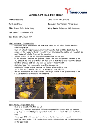
1. Development Team Daily Report
Name: Sasa Surlan Date: 22/12/13 to 08/01/14
Rig: Sedco Energy Supervisor: Paul Thomason / Craig Sprunt
OIM: Graeme Croll / Buddy Foster Water Depth: In between Well Maintenance
Date Start: 22th
December 2013
Date Finish: 08th
January 2014
____________________________________________________________________________
Date: Sunday 22nd
December 2013
Rebuild the lower choke valve in the sack store, lifted out and landed onto the wellhead
connector platform
Could not retract the parking cylinder on the transporter had to lift the bop to take the
weight off the transporter before it would retract. Cleaned out the parking bolt receptacle so
see if this would help for future parking operations
Skid the bop back to the set back are and locked in the parking bolts
Lifted the lower choke onto the platform. Used a 5 ton chain fall which we attached to the
100 ton hoist. We came up with the 5 ton chain hoist so that the failsafe was at the correct
level then attached a 1.5 ton come along and sucked it inside the BOP
Shut down to perform housekeeping around the subsea area.
Back loaded the new failsafe assembly that had the wrong gasket profile
3-1/16” dual block PN:M104 SN: A28337 Body-4130 ICN: 10013631
900 day inspection on the failsafe valves, found slight damage on the gate and seats of the
LIC. Decision made to install new gate and seats.
____________________________________________________________________________
Date: Monday 23rd
December 2013
Open up all bonnets. UPR. MPR and LPR
Connect a 1/2” hot-line from hotline regulated supply manifold. Using a valve and pressure
gauge trap and insure 1500 psi is kept on both locks. A hose is installed from one lock to the
other.
Slowly apply 1500 psi to open port for closing so that the nuts can be removed.
Using the Hytorc wrench (3 ¼”) remove all the bonnet nuts and install the ram extension rods
on the upper studs.
2. Vent ½” hot-line supply to open side of ram body and replace onto close side, slowly apply
pressure (500 psi max) until the bonnet is fully open. Prior to starting opening the bonnets
then ensure that the control hoses are removed from both open and close sides.
Vent ½” hot-line supply to close side of ram body and replace onto open side, slowly apply
pressure (500 psi max) until the ram block is fully retracted.
Prior to performing maintenance or inspections we vented all pressure from ram lock function
and the open and close function
Carried out an after action review on the WRA as there were a few items that were needing
expanded on and changed slightly. Mentioned that we need to have a hose installed to both
ramlocks and also that before retracting the ram block then we cannot have the ram tray
installed as there is a potential for hanging up on the ram tray.
____________________________________________________________________________
Date: Tuesday 24th
December 2013
Change out shuttle on open side of Upper Pipe Rams. Removed the 4 x ¾” Nuts from the front
of the shuttle. Once removed then a 3/8” allen key is used to remove the rest of the shuttle
from the body. Cleaned and inspected the sealing face on the body for the seal sub, some
slight corrosion evident.
New shuttle details
Part No. 27069-2
Serial No. G156387
Cleaned and dressed the BSR, UPR, MPR and LPR cavities so that cavity measurements can be
taken
Flush through the diverter with mixed stack magic from the hotline panel. A 14mm allen socket
is used to remove the plug from the flush port. Once removed a ¾” NPT Male to JIC 8 Male
adapter is installed so that a hotline can be hooked up. Flushed through for 15 mins with
approximately 200psi max. No major debris seen coming out. This done so that there is no
debris caught between the body and the drive sleeve.
Carried out dimensional checks of the BSR, UPR and MPR
____________________________________________________________________________
Date: Wednesday 25th
December 2013
Continued cleaning ram cavities and blocks ready for NDT inspection
Caught up on RMS jobs
__________________________________________________________________________
Date: Thursday 26th
December 2013
Spool off the hotline into an open top container ready for back load
NDT inspection carried out on all ram buttons & shear ram stud
Closed up the following bonnets: LPR – MPR – UPR
Started to reduce the stack accumulator N2 to 1500psi
___________________________________________________________________________
3. Date: Friday 27th
December 2013
Remove the bearing housing cover from the hotline reel main shaft and inspect bearing.
Bearing in good condition and moving freely. Cannot locate the new bearing, we have bearing
housings and drive sleeves but no actual bearing.
Bled down the system. Mix tank has been emptied in preparation for cleaning
Bring down the stack bottles pre-charge to 1500 psi. Starboard level 1 on the stack has been
reduced to 1500psi. 1 x Bottle in this bank needs increased as it is down at 1000psi (It has
been marked up)
____________________________________________________________________________
Date: Saturday 28th
December 2013
Put the bearing housing back together on the Hotline
Install a new swivel on the hotline reel. Part # 3207728 ICN 100
Found the bearing for the hotline in the store. New drive sleeve from clean workshop has been
put in the store so that we now have a complete set spare. The bearing on the port side has
been stripped down ready for change out. The starboard bearing cannot be changed out at the
moment as the disc brake is solid on the shaft and needs heat to be removed. We do not have
a spare so this is on hold until new disc arrives
Clean out the mix tank. 2 main hatches have been removed and the inside of the tank has been
cleaned and wiped down. The tank was not too dirty anyway. Sealing rubber was damaged on
both covers, fabricated new onse and installed on the tank.
Check the surface bottles pre-charge (1500 psi)
__________________________________________________________________________
Date: Sunday 29th
December 2013
Completed the bearing change out on the hotline reel
____________________________________________________________________________
Date: Monday 30th
December 2013
Removed the Lower choke fail safes and lower down to deck in preparation for changing out
the seal seats on the LIC.
Started to change out the oil in the HPU Pumps. Hyspin 68, 9 liters in each.
Troubleshoot the issues with the BOP HPU mix tank (Electrical)
____________________________________________________________________________
Date: Tuesday 31st
December 2013
Troubleshoot the issues with the BOP HPU mix tank (Electrical)
Change out 3 x barksdale manipulator valves on the slip joint panel. 1 x valve is left in stock.
Replace bladder from accumulator bank # 6 due to it being burst.
____________________________________________________________________________
4. Date: Wednesday 1st
January 2013
Continue to pre-charge surface accumulators
Spot check frame bolts on BOP
Troubleshoot the issues with the BOP HPU mix tank (Electrical)
Shut down on BOP due to overhead work on drill floor
Complete change out of 3 x barksdale valves on the slip joint panel.
____________________________________________________________________________
Date: Thursday 2nd
January 2013
Remove the kick out sub from the kill isolation valve to identify which profile we have on our
isolation valves. Isolation valves are “AX” and kick out sub is “AX” on bottom and “BX” on top.
Liaise with NDT inspector to have RHT inspected. Not available until tomorrow.
____________________________________________________________________________
Date: Friday 3rd
January 2013
Commission the Romar Panel.
Issue with PSU 2 power supply (Loose Wire)
Issue with air solenoid valve not closing when lower packer energized. Changed out the
solenoid.
All issues have been resolved and the ROMAR package is working correctly
Replace hose and check VLV on pump # 3 on the HPU
Install the bottom clamp on the co-flex on the kill side until we were shut down due to
overhead PRS work.
NDT Inspection carried out on RHT in sack store and is now ready for rebuild
Installed the bottom clamp on the co-flex on the choke side. Still needs to be torqued up.
Fingers have been installed on the RHT and have been lowered into the cam ring ready for
assembly.
____________________________________________________________________________
Date: Saturday 4th
January 2013
Installed the 4 x lifting points onto the upper annular body
Removed the upper annular open / close shuttles from the body and placed in the clean
workshop.
Rebuilt the RHT in the sack store and placed back into its basket
NDT Inspection carried out on RHT in sack store and is now ready for rebuild
Riser Adaptor, Flex joint, Upper Annular removed from LMRP
____________________________________________________________________________
Date: Sunday 5th
January 2013
Welder started to work on the DMAS alterations. Hole is cut on the LMRP aft side.
Rebuilt RHT in sack store.
Rig up to put the new hotline reel on to the spooler. Shaft of the spooler is too large to fit
through the drum. Tried to use a 3 ½” pipe but this just bent under the weight.
Covered the lower annular body as the mechanics were removing the 50 ton hoist above the
BOP.
5. Cleaned inside the upper annular body
Located the other single fail safe open isolation valve. In the forward end of the sack store
___________________________________________________________________________
Date: Monday 6th
January 2013
Continued to install the new hotline hose onto the reel. The hose has been installed onto the
reel but is around 1500ft to long and the reel is full. Decision needs to be made on what they
want to do as the hose will only be 8500ft if we have to cut it.
Rigged up to remove the LMRP from the lower BOP. Rigged up a hotline to the retract all stabs
function on the ROV panel. 1500psi was applied to the hotline. All stabs retracted but the
riser connector did not open. Rigged up a separate hotline hose to the riser connector “open”
side and the connector opened at 3400psi.
____________________________________________________________________________
Date: Tuesday 7th
January 2013
Instaling Part of DMAS hardware, Trriger on LMRP
Helping the Welder and good housekeeping, make worksite safe and ready for back to back’s
____________________________________________________________________________
Date: Tuesday 7th
January 2013
Report and handover.
____________________________________________________________________________
Lessons Learned
Amended the WRA for opening and closing the bonnets. There was a potential for someone to
make a mistake if the amendment had not been made due to the fact that it did not tell you to
pressure up both sides on the ram locks which could lead to the ram lock whistle pistons
gouging out the chamber on that side