This document summarizes a study to reduce noise levels in an automotive testing center's quiet room. Vibration from mechanical equipment on a floor above was transmitting noise through the ceiling into the quiet room, making low-level vehicle tests impossible. An investigation found the quiet room's suspended ceiling was not properly isolated from the floor above. Recommended fixes included improving the ceiling isolation, adding sound absorption, and breaking the floor to isolate vibration transmission. Initial phase 1 work above the ceiling showed promising results in lowering noise levels.
![Abstract
This paper presents the results of a study to reduce the background
noise level within a large Quiet Room located adjacent to other
laboratory testing environments and below a mechanical mezzanine
which houses an extensive array of mechanical and electrical
equipment including banks of low-temperature chiller compressors,
air handling units, and electrical switchgear that serves the entire
building complex. This equipment was installed atop the concrete
mezzanine floor deck without provisions for isolating vibration. As a
result, structure-borne noise from that equipment travels through the
floor, radiates from the underside of the floor deck, and intrudes into
the Quiet Room below. This causes the background noise level
within the Quiet Room to be too high for conducting low sound level
measurements and studies on vehicles brought into the Quiet Room.
Conclusions of the study are that provisions originally intended to
isolate the Quiet Room from the mezzanine floor deck were both
insufficient and poorly installed, resulting in excessive noise
transmitted into the Quiet Room. Recommended corrective measures
include enhancement of the Quiet Room ceiling to improve the sound
transmission loss performance of that assembly, and changes made to
the mezzanine floor deck to isolate structure-borne noise. This work
is being installed in phases and completion of the initial phase has
shown very promising results.
Introduction
A Quiet Room was built as part of the original construction of a
circa 1990s automotive technical center. The primary user of the
Quiet Room expressed concern that the background noise level/
spectrum in the Quiet Room was too high to conduct low level
vehicle noise investigations. This led to the initiation of a study to
determine the options and cost for reducing noise intrusion into the
Quiet Room from nearby mechanical and electrical equipment
installed on a mezzanine level floor deck that runs above and also
extends beyond the Quiet Room.
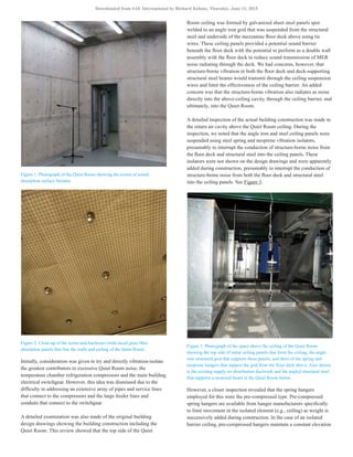
Anatomy of a Quiet Room
A Quiet Room is essentially a hemi-anechoic room that does not
necessarily meet the free-field requirements of ISO 3745 [1], and has
a sufficiently low background noise level/spectrum that is compatible
with conducting acoustical measurements on noise sources of
interest. The interior surfaces of a Quiet Rooms are generally lined
with highly sound absorbing, flat-faced acoustical panels, the
thickness of which define the low frequency extent of the free field.
The Quiet Room was site built with all wall and ceiling surfaces
faced with thick layers of semi-rigid, glass fiber sound absorption
panels that are layered with large airspaces to create a high degree of
sound absorption across a broad spectrum of sound. The glass fiber
absorption was faced with an off-white colored scrim, and stainless
steel hardware cloth. This was all held in place using stick-pins and
chromed buttons. This approach for sound absorption is considered to
be unconventional and provides a “home built” appearance. See
Figures 1 and 2. It is, however, expected to produce an estimated low
frequency cut-off of 182 Hz based simply on the total thickness of the
absorption relative to a quarter wavelength [2].
Diagnostic Investigation
The initial work of this study consisted of a detailed inspection of the
room construction and its juxtaposition relative to potential noise and
vibration sources that could adversely impact the Quiet Room. This
proceeded extensive noise and vibration measurements within the
Quiet Room, in the return air ceiling cavity above the Quiet Room,
and in the mechanical equipment room (MER) above the Quiet Room.
An Automotive Technical Center Quiet Room
Improvement Study - Part I
2015-01-2348
Published 06/15/2015
Richard Kolano
Kolano and Saha Engineers Inc.
CITATION: Kolano, R., "An Automotive Technical Center Quiet Room Improvement Study - Part I," SAE Technical Paper 2015-01-
2348, 2015, doi:10.4271/2015-01-2348.
Copyright © 2015 SAE International
Downloaded from SAE International by Richard Kolano, Thursday, June 11, 2015](https://image.slidesharecdn.com/ad54e2ed-3d49-4259-8059-170e4034c884-150827143951-lva1-app6891/85/SAE-Paper-2015-01-2348-1-320.jpg)
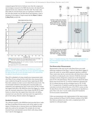
![of the ceiling as insulation and various layers of the ceiling are
installed, rather than allowing a gradual and continual drop in ceiling
elevation that would otherwise occur. Once the ceiling loading
exceeds the pre-compression setting, the elements that create the
pre-compression become disengaged and no longer are in contact. At
that point, the ceiling load “breaks free” and the springs deflect
slightly further to their final position.
Additional review of the isolating spring hangers that had been
selected and installed to support this Quiet Room ceiling showed that
these hanger springs were pre-compressed by the manufacturer to an
equivalent load of 60 kg (133 lb) per hanger [3]. This was 60% of the
maximum load rating of 101 kg (222 lb) per hanger. The combination
of choosing hangers with load capacities that are too high for this
ceiling under typical isolator spacing, and the use of an excessive
number and concentration of hangers to support this ceiling resulted
in an estimated average loading of less than 32 kg (70 lb) per isolator.
It should be noted here that the installed spacing of the isolators was
not in a simple rectangular pattern, but was instead somewhat
irregular. This approach was chosen by the installation contractor in
part to work around ductwork serving the Quiet Room (see Appendix
for an illustration). The net result was that after construction, most
spring isolators remained in a pre-compressed state such that the
effectiveness of the springs for isolating vibration was compromised
(short-circuited) by the nuts and washers installed to create the
pre-compression. See Figure 4 for a view of one of the compromised
hangers caused by the pre-compression nut and washer.
Figure 4. Photograph of the above-ceiling space with a close-up of the bottom of
one of the isolation hangers. The red arrow indicates the pre-compression nut
that forces the washer against the bottom of the housing causing a “short-
circuit” of the spring and allows vibration to travel down to the ceiling panels.
In addition, inspection of the above-ceiling cavity revealed that there
are three sets of steel framing elements that connect to the underside
of floor-supporting steel, angle downward to penetrate the barrier
ceiling plate, and support a horizontal beam to which a monorail beam
along the top and center of the Quiet Room is bolted. See Figure 5.
These steel framing elements provide a direct path for structure-borne
vibration from the underside of the MER floor deck to the monorail
beam. A photo of one set of this framing (viewed from the above-
ceiling cavity above the Quiet Room) is provided in Figure 6.
Figure 5. Photograph of the monorail beam for a hoist that traverses the
centerline of the Quiet Room in a ceiling recess.
Figure 6. Photo of angled steel framing members that extend down from the
floor deck to support the end of one of three horizontal beams that support the
Quiet Room monorail beam that runs in a ceiling recess along the center of the
Quiet Room. These steel members were also found to conduct vibration into
the metal ceiling panels.
Acoustical Measurements
Measurements were made of the background noise level in the Quiet
Room under various operating conditions of MER equipment. Refer
to Figure 7. Measurements were made in octave bands and compared
against the target noise limit of noise criterion (NC) 15 dB [4]. These
measurement results show that operation of the MER refrigeration
compressors is the most significant contributor to excessive Quiet
Downloaded from SAE International by Richard Kolano, Thursday, June 11, 2015](https://image.slidesharecdn.com/ad54e2ed-3d49-4259-8059-170e4034c884-150827143951-lva1-app6891/85/SAE-Paper-2015-01-2348-3-320.jpg)
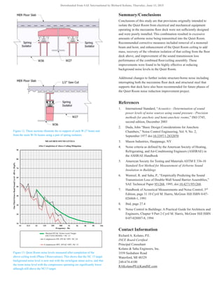
![Figure 7. Third-octave band noise levels measured in the Quiet Room for
various MER equipment operating conditions compared against the (octave
band) target goal of NC-15.
Room noise. Noise produced by the electrical switchgear was also
found to be a significant contributor to noise in the Quiet Room.
One-third octave band sound pressure level (1/3 OB SPL)
measurements were also made at key locations under specific MER
equipment operating conditions to better understand the noise
intrusion into the Quiet Room. Figure 8 shows the 1/3 OB SPL
measured in the MER at positions ranging from close to and distant
from the refrigeration compressors with the compressors in operation
as well as the switchgear energized. Also shown is the spectrum of
noise measured in the ceiling cavity above the Quiet Room and in the
center of the Quiet Room. These results show that pronounced
spectral peaks in the third-octave bands of 63, 125, 250, and 500 Hz
exist in the MER, within the ceiling cavity, and in the Quiet Room.
Measurements were made of the airborne sound transmission loss
(STL) performance of the floor-ceiling construction separating the
Quiet Room from the mechanical equipment room above using the
test procedure of ASTM E 336 [5]. Measurements were also made
of the noise reduction (NR) versus third-octave band frequency
between the MER and the above-ceiling cavity above the Quiet
Room to approximate the STL of the floor deck alone. These are
plotted in Figure 9 compared against laboratory measured STL data
for the two respective floor and floor-ceiling constructions. It should
be noted that because the actual laboratory STL performance for the
overall floor-ceiling assembly was not readily available, the
performance was estimated using empirical calculations based upon
a combination of the STL of elements that were individually
laboratory tested for STL performance (i.e., 6″ concrete and 18 ga.
sheet steel) [6]. Based upon this comparison, it is clear that the
concrete floor deck performance is reasonably close to that expected
based upon laboratory test data. However, the floor slab in
conjunction with the suspended 18 ga. steel barrier produces
considerably less than its potential as demonstrated by comparison
against laboratory test data. This is attributed to the lack of resilient
suspension of the barrier steel panel ceiling, which is the direct
result of the compromised vibration isolation performance of the
pre-compressed spring hangers.
Figure 8. Third-octave band noise levels measured in the Quiet Room before
corrective measures, as well as above the Quiet Room ceiling, and at several
positions in the MER for various MER equipment operating conditions
compared against the (octave band) target goal of NC-15.
It should also be noted that the apparent drop in STL performance at
125 Hz is actually due to background noise in the measurements
originating from the MER switchgear which could not be turned off
for this investigation (see field test results provided in Figure 9).
Recommended Corrective Measures
Corrective measures for reducing noise intrusion into the Quiet Room
were identified to correct design and construction deficiencies
discovered during this investigation. These included reworking the
suspension system which supports the barrier ceiling plate above the
Quiet Room, and related actions which reduce the airborne and
structure-borne noise transmission into that ceiling barrier. In
addition, a method for interrupting structure-borne noise through the
MER floor deck was also identified. This consisted of first saw-
cutting the floor deck to create a physical break in the otherwise
continuous slab, and second, to interrupt the structure-borne path
through structural steel beams that support that floor deck. The latter
Downloaded from SAE International by Richard Kolano, Thursday, June 11, 2015](https://image.slidesharecdn.com/ad54e2ed-3d49-4259-8059-170e4034c884-150827143951-lva1-app6891/85/SAE-Paper-2015-01-2348-4-320.jpg)
![would be achieved by breaking the contact between the ends of those
beams and the main beams along column lines that support the beam
ends. The “freed” ends of these floor-supporting beams would then be
supported using spring isolators. These corrective measures were set
up to be implemented in three separate phases. This approach allows
for measurements of Quiet Room noise levels upon completion of
each phase to determine the effectiveness of the work conducted in a
given phase before proceeding with the next phase.
Figure 9. This graph shows a comparison of the third-octave band sound
transmission loss performance of a 6″ concrete floor slab with and without an
18 ga. steel barrier suspended 60″ below the floor slab. Shown are laboratory
versus field measured values.
Phase I: Above-Ceiling Work
Several correction measures were recommended for above the Quiet
Room ceiling. The first was to reduce the number of isolators that
support the ceiling from 100 to 72 by strategically removing isolators
to make the spacing as even as possible. The second was to increase
the loading across the ceiling plate by installing two layers of 1.6 cm
(5/8″) drywall cut to fit the cavities formed by the angle iron framing,
in addition to a viscoelastic damping adhesive. Third was to overlay
the entire ceiling with 10 cm (4″) of mineral wool sound absorption
batts. The insulation adds additional weight across the ceiling plate,
and introduces sound absorption to the above-ceiling cavity. The
added mass and absorption reduces the mass-air-mass resonance of
the double wall system and thereby increases the STL performance of
the floor-ceiling [See the Appendix] [7]. The added absorption also
reduces sound passage through this cavity which serves as a return air
plenum for ventilating the Quiet Room.
With the added weight of the drywall, damping, and insulation, plus
the reduced numbers and reconfiguring of the spring hangers, the
estimated total average loading per isolator is 72 kg (159 lb). This
loading is both greater than the pre-compression setting of 60 kg (133
lb) and yet below the maximum hanger capacity of 101 kg (222 lb)
[Refer to the Appendix].
The increased loading on each spring hanger was expected to
overcome the pre-compression short-circuiting and allow the barrier
ceiling to fully decouple from the MER floor above. The increased
hanger loading was also expected to produce an average deflection of
1.8 cm (0.7″) in the isolator springs, which should produce a vibration
isolation efficiency of 98% at 30 Hz, the lowest frequency of interest
as determined from vibration measurements on the floor and structural
steel. This degree of isolation efficiency tells us that the spring hangers
will no longer compromise the double-wall STL performance of the
floor/ceiling assembly [Refer to the Appendix] [8] [9].
Figure 10 shows the previously mentioned STL performance of the
existing floor-ceiling construction between the MER and Quiet Room
compared against the expected double wall STL for that assembly
empirically determined using laboratory measured STL values for
each individual element of the construction.
Also shown as a third curve is the estimated STL of the improved
floor-ceiling construction after installation of the following
recommended improvements:
1. The steel panels are overlaid with 2 layers of 1.6 cm (5/8″)
drywall attached using a vibration damping adhesive.
2. The number and spacing of existing spring hangers are reduced
and reconfigured to overcome the pre-compression condition.
3. The drywall-backed ceiling panels are overlaid with a 10 cm
(4″) thick layer of mineral wool acoustical absorption material.
Another recommendation was to remove the rarely (if ever) used
monorail and hoist from the Quiet Room (see Figure 5), including all
of the steel elements that originate at the underside of the MER floor
deck above (see Figure 6). This would remove a second major path of
structure-borne noise that gets induced into the barrier ceiling plate as
well as eliminate a source that radiates this structure-borne noise
directly into the Quiet Room.
Phases II & III: Mezzanine Floor Deck Isolation
As of this writing, the Phase I: Above-Ceiling Work was completed.
Subsequent work is planned and will be divided into phases. Phase II
consists primarily of using a masonry saw to cut through the entire
floor slab and deck parallel and close to the upper web of the main
floor-supporting beam along the column line at two locations. This
saw cutting is expected to create a 1.2 cm (0.5″) gap in the floor deck
to interrupt structural-borne noise (vibration) induced in that floor
slab by the low temperature chiller compressors and electrical
switchgear which both rest directly atop the slab without any
deliberate means of vibration isolation. This excitation travels
through the floor slab and radiates as airborne sound into the ceiling
cavity above the Quiet Room. Levels of compressor and switchgear
noise measured in this cavity are higher than expected when
Downloaded from SAE International by Richard Kolano, Thursday, June 11, 2015](https://image.slidesharecdn.com/ad54e2ed-3d49-4259-8059-170e4034c884-150827143951-lva1-app6891/85/SAE-Paper-2015-01-2348-5-320.jpg)
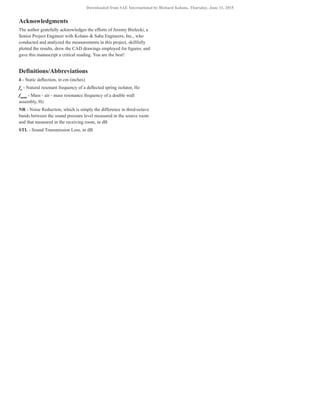
![APPENDIX
The Quiet Room ceiling was originally built using 100 spring isolators to support the weight of the ceiling from the underside of the Mechanical
Equipment Room floor deck above. Figure A1 shows the original (“as-built”) layout of the isolators. Also shown is the supply air ductwork that
serves the Quiet Room. The layout of this ductwork as well as the dimensions of the angle iron grid both influenced the original spacing and
placement of the isolators.
Figure A1 includes a color coding of the existing, originally installed spring isolators to indicate which of those isolators should be removed and/or
relocated to create a more equal distribution of the ceiling weight across the array of isolators without creating excessive spans for the angle iron grid
which supports the ceiling panels and without under loading or overloading any given isolator.
Figure A1. Quiet Room Ceiling Isolators Color Code (Before):Green =
Existing, to RemainBlack = Existing, to be RemovedRed = Pairs of Existing
Isolators to be Removed and Replaced with a Single Isolator
Figure A2. Quiet Room Ceiling Isolators Color Code (After):Green = Final
Layout after Excess Isolators are Removed or Repositioned
Figure A2 shows the revised isolator layout that was developed based upon maintaining the original angle iron grid, the added weight of the
additional drywall and insulation, and the need to increase the average loading of the isolators to something greater than the pre-compression loading.
This approach resulted in the use of 72 isolators to support the ceiling with the increased loading.
With 72 isolators and a total improved ceiling weight estimated to be 5179 kg (11,417 lb) (± 10%), each isolator will support 64 to 79 kg (142 lb to
174 lb) or about 72 kg (159 lb) on average and produce a static deflection of 1.8 cm (0.7″). Since the rated capacity of each existing isolator is 101 kg
(222 lb), a 60% pre-compression of the isolators requires a load of at least 60kg (133 lb) to overcome the pre-compression.
The mass - air - mass resonance frequency (fmam
) of a sealed double wall system establishes the frequency at which double-wall sound transmission
loss performance begins to be achieved. The fmam
of a double wall system can be determined using the following equation [7]:
Where fmam
= mass-air-mass resonance frequency, Hz
m1
= surface mass of the first wall, kg/m2
m2
= surface mass of the second wall, kg/m2
d = separation between the two walls, mm
K = 60 for an empty cavity; 43 for a cavity filled with sound absorptive material
Downloaded from SAE International by Richard Kolano, Thursday, June 11, 2015](https://image.slidesharecdn.com/ad54e2ed-3d49-4259-8059-170e4034c884-150827143951-lva1-app6891/85/SAE-Paper-2015-01-2348-9-320.jpg)
![In this case, the fmam
for the original floor-ceiling assembly is expected to be 10 Hz. With the improvements described here-in, the fmam
of the
floor-ceiling is reduced to 7 Hz. This assumes that air alone is the only element that acoustically couples the two masses, and that there is no absorber
within the airspace. When the double wall system is actually vertically separated elements, such as the Quiet Room sound barrier ceiling suspended
below the MER floor deck, the mass-air-mass frequency is not the only consideration. Also of concern is the stiffness of the elements that structurally
support the barrier ceiling. This should also be considered, especially if the suspension system is stiffer than air. In such a case, the resonant
frequency of the suspension system would be higher than the mass - air - mass resonance frequency of the floor and ceiling, thereby limiting the
effectiveness of the double wall system for achieving high STL performance. In the experience of the author, practice has shown that the resonant
frequency of the resilient suspension system for a massive ceiling hung below a structural floor deck may create a limiting condition if that resonant
frequency is too high (i.e., above the mass - air - mass resonance frequency of the floor-ceiling system). In such a case, structure borne vibration
measured in the floor may be transmitted through the elements that are supporting the ceiling and result in sound radiation from the barrier ceiling
plane which is at a higher magnitude than would be expected simply from the sound transmission loss performance of the decoupled floor-ceiling and
the source level/spectrum of noise measured in the space above that floor. As a result, the deflection and resonant frequency of the spring hangers that
support the Quiet Room ceiling were initially a concern, and remained a concern following implementation of the recommended measures that
allowed that ceiling to “break free” from the pre-compression settings of the isolation hangers. The concern was that even with the increased ceiling
loading, and the average 1.8 cm (0.7 inches) deflection expected from the isolator springs, there may continue to be conduction of structure borne
noise through the spring hangers at low frequencies which would reduce the double-wall STL of the floor/ceiling assembly at low frequencies. Based
upon the following equation [8], the average deflection of the spring hangers is expected to produce a resonance frequency of 3.7 Hz.
Where fn
is the natural resonant frequency of the deflected spring isolator, K is a constant of 15.8 (3.13 for I-P) and δ is the deflection of the spring
isolator in millimeters (inches).
This average spring deflection is also expected to produce a vibration isolation efficiency of greater than 98% at frequencies above 30 Hz, which is
the lowest frequency of interest as determined from vibration measurements on the MER floor and structural steel. This isolation efficiency is based
upon the following equation [9]:
Vibration Isolation Efficiency
Where fd
is the frequency of the disturbance which is to be isolated and fn
.is the natural resonant frequency of the spring isolator.
With vibrational energy passage through the spring hangers reduced by 98% (or more), any reduction in the double wall STL due to structure borne
noise transmitted through the spring hanger becomes negligible. This agrees with our standard practice of assuring that any resonant elements which
potentially couple the opposing sides of a double wall assembly be selected so that the natural resonant frequency of those elements are below (less
than) the fmam
of the double wall assembly.
The Engineering Meetings Board has approved this paper for publication. It has successfully completed SAE’s peer review process under the supervision of the session organizer. The process
requires a minimum of three (3) reviews by industry experts.
All rights reserved. No part of this publication may be reproduced, stored in a retrieval system, or transmitted, in any form or by any means, electronic, mechanical, photocopying, recording, or
otherwise, without the prior written permission of SAE International.
Positions and opinions advanced in this paper are those of the author(s) and not necessarily those of SAE International. The author is solely responsible for the content of the paper.
ISSN 0148-7191
http://papers.sae.org/2015-01-2348
Downloaded from SAE International by Richard Kolano, Thursday, June 11, 2015](https://image.slidesharecdn.com/ad54e2ed-3d49-4259-8059-170e4034c884-150827143951-lva1-app6891/85/SAE-Paper-2015-01-2348-10-320.jpg)


