Download to read offline
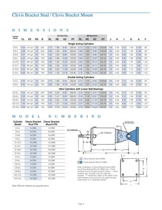
![Type: S = Single Acting Cylinder
US = “Ultra” Cylinder with Ball Bearing
D = (Available Long Stroke Only)
Double Acting Cylinder (Available Size 4, 9 Only)
Size: Effective Area (Square Inches)
Stroke: S = Short Stroke
L = Long Stroke
(See Operating Parameters for selection.)
Rod Threads: CA = ControlAir Inc. Standard
SM = National Fluid Power Association Standard
Mount Type: UM = Universal Mount (Standard Mounting p.3)
See page 4 & 5 for optional mounting styles
(To order Rod Clevis see Rod Clevis Dimension section on p.6)
Note: Cap Mounting Studs will be provided only when requested or required
by mount option selected. See Page 6.
Standard Options: NS = No Spring
NB = No Bearing
NBS = No Spring and No Bearing
NOTE: Add to end of ordering number if desired, otherwise leave blank.
Options available for single acting cylinders only.
Mounting Studs: WITH STUDS = mounting studs on cap and supplied
NO STUDS = mounting studs on cap end not supplied
Note: If cap mounting studs are NOT desired add "no studs"
to end of ordering data. Default is WITH studs. (see page 6)
Ordering Information
Use this coding system to order
Operating Parameters
• • • • • • •
S - 16 - S - CA - UM - NBS
Example
Single Acting Cylinders
Cylinder Model Effective Area Equivalent Bore Stroke Initial Spring Spring Rate Weights
Standard Ultra (inches) (inches) (inches) Force (lbs.) (lbs./inch) (lbs.)
S-4-L US-4-L 4 2.3 1.8 9 4 1.6
S-6-L US-6-L 6 2.8 2.4 9 4 2.3
S-9-S 9 3.4 2.2 17 4 5.3
S-9-L US-9-L 9 3.4 3.0 12 4 4.0
S-12-S 12 3.9 2.3 18 6 8.0
S-12-L US-12-L 12 3.9 3.6 18 6 9.5
S-16-S 16 4.5 2.6 24 8 11.0
S-16-L US-16-L 16 4.5 4.2 24 8 12.0
Double Acting Cylinders
D-4-L 4 2.3 1.3 2.0
D-9-L 9 3.4 2.5 4.5
NOSTUDS
Page 2
Operating Information
Pressure Airline pressures up to 145 psi (10 BAR)
Temperature -40˚to 225˚F (-40˚ to 107˚C)
Materials
Cylinder Shell Anodized Aluminum(sizes 4-9),Steel(sizes12-16)
Head Aluminum (sizes 4-16)
Piston Aluminum (sizes 4-9), Steel (sizes 12-16)
Rod Chrome Plated Steel
Diaphragm Neoprene Rubber with Dacron Fabric
Approximate Forces
How to determine the force generated by a cylinder
Force = Airline Pressure x Effective Area less Spring Force
Effective Area = Cylinder Size
F = P (AE) - [FO + K (S)]
F = Cylinder Force
P = Working Pressure
AE = Effective Pressure Area
FO = Spring Force at zero stroke
K = Spring Rate
S = Stroke](https://image.slidesharecdn.com/aircylspec-170310152253/85/Rolling-Diaphragm-Air-Cyclinders-for-Linear-Motion-2-320.jpg)

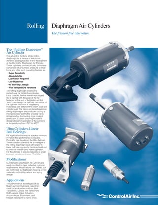
The document describes ControlAir's rolling diaphragm air cylinders, which provide low-friction pneumatic pressure conversion with features like no lubrication required and low hysteresis. It details the design and benefits of the rolling diaphragm and introduces the ultra cylinder with linear ball bearings for enhanced performance. Additionally, it outlines various cylinder models, modifications, applications, and ordering information, emphasizing their suitability for tasks such as valve actuation and tension control.