The recognition of human walking and running actions becomes essential part of many different practical applications such as smart video-surveillance, patient and elderly people monitoring, health care as well as human-robot interaction. However, the requirements of a large spatial information and a large number of frames for each recognition phase are still open challenges. Aiming at reducing the number frames and joint information required, temporal foot-lift features were introduced in this study. The temporal foot-lift features and weighted KNN classifier were used to recognize “Walkin and“Running”actions from four different human action datasets. Half of the datasets were trained and the other half of datasets were experimentally tested for performance evaluation. The experimental results were presented and explained with justifications. An overall recognition accuracy of 88.6% was achieved using 5 frames and it was 90.7% when using 7 frames. The performance of proposed method was compared with the performances of existing methods. Skeleton joint information and temporal foot-lift features are promising features for real-time human moving action recognition.
![ISSN 3047-5473
Innovation in Engineering, Volume 1, Nomor 1, 2024, pp. 1-20
2 | P a g e
be implemented only by human security and thus the applications of smart video
surveillance systems are essentially important [1]. In addition, human recognition is
importantly used in human-robot interaction such as human-following robots, sport-
robot and so on.
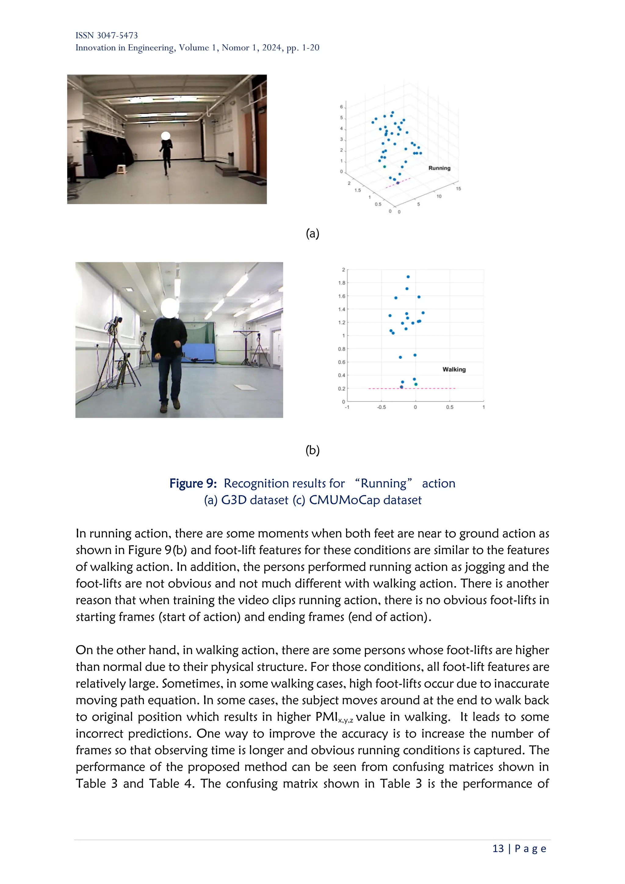
(a) (b) (c)
Figure 1: Instantaneous human moving actions in different applications
(a) human-following robot (b) public surveillance system (c) sport-robot
In literature, human action recognition was started using the signal of the LED light bulbs
attached on different parts of human body [2]. In that approach, the motion vector
analysis of LED bulb signal was applied to differentiate the “Walking” and“Running
”actions. This approach required dark environment to capture the LED bulb signal. Su
et al. [3] proposed an automatic gait recognition method based on the motion frequency
characteristics of three parts of human silhouette; trunk, thigh and shin. The “Running
” action was marked with a high motion frequency and “Walking” action marked
with a low motion frequency. In the approach proposed by Masoud et al. [4] eigen
images were used as the features for recognizing“Walk”,“Run”,“Skip”,“March,
Line-walk”,“Hop”,“Side-walk”,“Side-skip”actions. It required a total of 50
binary image frames to develop eigen images and eigen vectors. Köse et al. [5] utilized
Pixel Motion Features (PMI) for recognition six different actions including“Walking”
and“Running”.
The PMI feature is the cumulative summation of frame difference for a certain number
of consecutive frames during a time duration. The authors used eight cameras to capture
eight perspectives of motion and calculate the PMI. The “Running” action resulted in
large PMI values and the“Walking” action resulted in small PMI values. The
effectiveness of duty factor for recognizing “Walking”, “Jogging” and “Running”
[6]. Their method consisted of two steps. First, the gait type was classified and then action
recognition was recognized based on duty factor in the second step. The duty factor is
the total time when one foot is touching to the ground during one stride. In their
approach, at least two strides were still needed. These earlier studies have mainly focused
on learning and recognizing actions using RGB images. However, application of RGB
video/images have limitations when human body parts are occluded due to self-
occlusion or objects around when performing action.](https://image.slidesharecdn.com/1-articletext-29-5-10-20240513-250629181353-e546d411/75/Recognition-human-walking-and-running-actions-using-temporal-foot-lift-features-2-2048.jpg)
![ISSN 3047-5473
Innovation in Engineering, Volume 1, Nomor 1, 2024, pp. 1-20
3 | P a g e
Thus, today the application of RGB-D and 3D skeleton-joint information becomes
popular for recognition of different human actions . Compared to RGB images, the depth
information or skeleton joint data can give 3D posture and additional features of human
body during actions [7], [8]. It realizes the possibility of 3D actions recognition [9], [10],
[11], [12]. A total of 16 joints features were utilized in the study of Ghazal et al.[13]. Here,
the displacements of left/right shoulder, left/right hip, left/right knee left/right ankle
between consecutive frames were calculated as dynamic features. Kim et al. [14]
proposed weakly-supervised 3D network for recognition of different actions including
“Walking” and “Running” actions. However, it still requires at least 16 temporal
frames.
From this literature survey, two challenges are observed. The first challenge is related to
the requirement of large spatial information. Using skeleton joint information of the
whole human body not only increases the computational complexity but also requires a
larger memory space because there are 15 to 30 joint locations on entire body [11]. There
will be more than 45 data points in each frame when fifteen 3D joints are considered.
Thus, when hundreds of frames are used in each recognizing phase, there will be triple
number of data to be handled in calculation. Sometimes, multiple cameras or multiple
views are necessary for achieving a good classification performance. It not only increases
the computational complexity but also requires larger memory space to keep the entire
database [15].
The second challenge is the requirement of a large number of frames (in other words
long duration of action) for recognizing human action. In [16], 5-s long video with 125
frames were required for each recognition phase. In other works [10], [17], [18], [19] a
minimum of 300 frames is required to extract spatiotemporal features in conventional
dual-stream model. In approach of using adaptive energy images [20], a total 70 to 100
frames must be applied. Even the whole video clip was used in [21]. These two challenges
motivated us to consider and contribute the concept of temporal foot-lift features using
a small number of frames for recognizing “Walking” and “Running” actions as
suggested in a previous work [22].
In this regard, the objectives of this study are to propose a method for recognizing human
“Walking” and “Running” actions using temporal foot-lift features extracted from a
small number of frames and to experimentally evaluate the performance using four
different datasets.
2. Material and methods
2.1 Skeleton joint data and foot-lift
Today, the skeleton joint data of human body in actions can be extracted using RGB-D
camera and Kinet Software [23] . There are a number of skeleton joint information
datasets of different human actions and freely available for research purpose [24], [25],
[26], [27]. Depending on the number of capturing locations, there can be many key joint](https://image.slidesharecdn.com/1-articletext-29-5-10-20240513-250629181353-e546d411/75/Recognition-human-walking-and-running-actions-using-temporal-foot-lift-features-3-2048.jpg)
![ISSN 3047-5473
Innovation in Engineering, Volume 1, Nomor 1, 2024, pp. 1-20
4 | P a g e
locations from which 3D skeleton joint information are extracted. A sample of skeleton
joints for in-door“Walking”action from UTKinet dataset is shown in Figure 2. It has 15
joint locations from head to foot.
This section explains the idea of using foot-lift features. Indeed, people may perform“
Walking”and“Running”as a single action or a combined action together with other
action. In our daily activities, the upper body part of human can have another activity
while walking or running. For examples, carrying box while walking, talking on phone
while walking, carrying pole vault or bag while running as shown in Figure 3.
Figure 2: Skeleton joint data [24]
When the whole-body information is taken into account, there are two disadvantages in
training the model. First, a large data must be handled and second the upper body part
can have many different actions. To avoid these disadvantages and to be able to integrate
the proposed method in any activity recognition, only foot-lift is considered for
recognizing fundamental “Walking” and “Running” actions. As shown in Figure 4,
there are distinct foot-lift characteristics in “Walking” and “Running” actions. It can
be noticed that foot-lifts in “Running” action are higher than foot-lifts in “Walking”
action. Therefore, it is considered to extract (predictors) features from foot-lift. Then,
this concept requires only information of foot joint locations rather than all joints’
information. It addresses the first challenge. To address the second challenges, temporal
foot-lift features are considered. Instead of using a large number of frames, foot-lift
features can be extracted using a small number of frames. In this study, 5~7 frames are
taken for each recognition phase.
1 Head
2 Neck
3 Right Shoulder
4 Right Elbow
5 Right Hand
6 Left Shoulder
7 Left Elbow
8 Left Hand
9 Torso
10 Right Hip
11 Right Knee
12 Right Foot
13 Left Hip
14 Left Knee
15 Left Foot](https://image.slidesharecdn.com/1-articletext-29-5-10-20240513-250629181353-e546d411/75/Recognition-human-walking-and-running-actions-using-temporal-foot-lift-features-4-2048.jpg)
![ISSN 3047-5473
Innovation in Engineering, Volume 1, Nomor 1, 2024, pp. 1-20
5 | P a g e
Figure 3: Some possible human actions while walking and running
Figure 4: Foot lift in “Walking” and “Running” actions
2.2 Block diagram
Figure 5 shows the process flow diagram of the proposed method. There are two phases
in which the first phase is video capturing and skeleton joint data extraction for the
actions. The first phase was done by previous research works which developed the
datasets [24], [25], [26], [27]. Today, there are many approaches to extract skeleton
joint data from recorded images or videos. Some researchers [28] used estimation of
vertical position of the neck, shoulder, waist, pelvis, knee, and ankle set by a study of
anatomical data to be 0.870H, 0.818H, 0.530H, 0.480H, 0.285H, and 0.039H,
respectively. However, it only works for extracting 2D skeleton joints in walking action.
The other approach is using various RGB-D sensors such as Microsoft Kinect, Intel
RealSense, OrbbecAstraPro and so on. In this approach body parts segmentation is
performed in RGB images using readily available deep learning models. Then, the dept
information is extracted from depth-image and used to develop 3D posture and skeleton
joint data. The other approach is using optical motion capture system based on retro-
Walking
Running](https://image.slidesharecdn.com/1-articletext-29-5-10-20240513-250629181353-e546d411/75/Recognition-human-walking-and-running-actions-using-temporal-foot-lift-features-5-2048.jpg)
![ISSN 3047-5473
Innovation in Engineering, Volume 1, Nomor 1, 2024, pp. 1-20
6 | P a g e
reflective markers attached to the actor’s body. This approach was used in MoCap
dataset [27].
Figure 5. Block diagram of proposed method
The second phase was conducted in this study. Based on the proposed method, the
temporal foot-lift features were calculated using skeleton joint information. The detailed
procedure for foot-lift feature calculation is explained in the next section. A half of the
observations was used for training and developing KNN classification model. Then, the
other half of observations was used for testing and evaluating the model.
2.3 Foot-lift features
Before discussing foot-lift features, it is necessary to understand what foot-lift is. The foot-
lift is the perpendicular height of the foot from the moving path (e.g, floor, ground)
during walking or running as shown in Figure 6. To calculate the foot-lift features, foot-
lifts of both feet must be firstly calculated. In this proposed method feet are assigned as
lower foot and higher foot but not left and right. It makes calculation more flexible and
independent of moving direction.
Figure 6 depicts the concept of calculating foot-lift in an image frame. From a skeleton
joint data in an image frame, the coordinates [(xf1, yf1, zf1), (xfh, yfh, zfh)] of feet locations
were taken. Here, (xf1, yf1, zf1) is lower foot location and (xfh, yfh, zfh) is the higher foot
location.
Capture video of
human moving
action
Extract skeleton
joints information
Extract temporal
foot-lift features
Phase-I
Test and evaluate
the model
Train and develop
model
Phase-II
50%
50%](https://image.slidesharecdn.com/1-articletext-29-5-10-20240513-250629181353-e546d411/75/Recognition-human-walking-and-running-actions-using-temporal-foot-lift-features-6-2048.jpg)
![ISSN 3047-5473
Innovation in Engineering, Volume 1, Nomor 1, 2024, pp. 1-20
7 | P a g e
Figure 6: Moving path and foot-lift in a movie frame
First it needs to find a short moving path on the ground/floor. Since it is a short path
during a small number of frames, it is considered as a linear line. Thus, straight line
equation was used. To find the moving path equation, the coordinate (xf1, yf1, zf1) was
used. At least three coordinates are required to develop a linear equation. Therefore, at
least three consecutive frames are required to find moving path equation. Here, only 2D
(XY or ZY, XY in Figure 6) path line is considered because each recognition phase is
implemented during a very short time.
α α
= +
fl 1 fl 2
y x (1)
where, xfl=[xfl1, xfl2, xfl3,…, xfln], yfl= [yfl1, yfl2, yfl3,…, yfln] are vectors of coordinates of
lower foot from n consecutive video frames. In this work, the number of frames (n) is set
as 5 and 7. After calculating 1 and 2 by means of linear regression method, yp on the
moving path can be calculated at any xp.
α α
= +
p 1 p 2
y x
(2)
Δ h fh p
y y y
= −
(3)
Δ l fl p
y y y
= −
(4)
Δ l
fl
m
y
R
H
=
(5)
Δ h
fh
m
y
R
H
=
(6)
Y
xfh, yfh, zfh
X
xp, yp
xfl, yfl, zfl,
Moving path
Z
Ground/Floor](https://image.slidesharecdn.com/1-articletext-29-5-10-20240513-250629181353-e546d411/75/Recognition-human-walking-and-running-actions-using-temporal-foot-lift-features-7-2048.jpg)
![ISSN 3047-5473
Innovation in Engineering, Volume 1, Nomor 1, 2024, pp. 1-20
8 | P a g e
where, yp is y-coordinate on moving path at any foot location xp (it should be xfh for
higher foot location, xfl for higher foot location), yl is lower foot lift, yh is higher foot-
lift, Hm is human height, and Rfl is normalized lower foot-lift, Rfh is normalized higher
foot-lift. For example, when n is set as 5 or 7, Rfl and Rfh become vectors as [Rfl1, Rfl2, Rfl3,
Rfl4, Rfl5] and [Rfh1, Rfh2, Rfh3, Rfh4, Rfh5] respectively.
After calculating foot-lifts for both higher and lower feet, first three foot-lift features were
calculated by means of the following equations.
Δ fh fl
fm
R R R
= − (7)
fmax fh
R max([R ])
= (8)
( )
2
n
rms fhi fli
i 1
1
E R R
n =
= −
(9)
where, Rfm is difference of means of normalized lower foot-lifts and normalized higher
foot-lifts, Rfmax is maximum normalized foot-lift, Erms is root-mean-square error between
lower foot-lifts and normalized higher foot-lifts.
Then, the dynamic features are referred as the ones for which a time duration is required
in calculation. In this work, the video recording frame rate is 30 fps. Therefore, the time
duration is 0.167 s for 5 frames and 0.233 s for 7 frames. For this work, two dynamic
features were considered as follow. To find the fairness among different physical
structures of actors, the normalized values are calculated. These features can be expressed
in mathematical forms as follow.
n
y fl fl fh fh
i 1
m
1
PMI y (i) y (i 1) y (i) y (i 1)
H =
= − + + − +
(10)
n
x,y,z fl fl fl fl fl fl fh fh fh fh fh fh
i 1
m
1
PMI x ,y ,z (i) x ,y ,z (i 1) x ,y ,z (i) x ,y ,z (i 1)
H =
= − + + − +
(11)
where, PMIy is pixel motion feature in Y-direction and PMIx,y,z pixel motion feature in x,
y, z directions. Since only two feet locations are required, there is no effect of the number
of joints available. It is a new version of pixel motion feature (PMI). Originally, the PMI
can be developed using binary image difference. The larger PMI values represent running
action and lower PMI values represent walking action. Here, since RGB images are not
used, joints coordinate differences are used. The first one is the cumulative sum of
absolute vertical displacements of feet during n frames (5, 7 frames or 0.167 s, 0.233 s).
The second one is the cumulative sum of absolute 3D displacements of feet during n
frames (5, 7 frames or 0.167 s, 0.233 s).](https://image.slidesharecdn.com/1-articletext-29-5-10-20240513-250629181353-e546d411/75/Recognition-human-walking-and-running-actions-using-temporal-foot-lift-features-8-2048.jpg)
![ISSN 3047-5473
Innovation in Engineering, Volume 1, Nomor 1, 2024, pp. 1-20
9 | P a g e
Sample features for “Running” and “Walking” are shown in Figure 7. It can be seen
that typically the foot-lift features of “Running” action are higher than the features of
“Walking”. It supports in classification. The step-by-step procedure for calculating
temporal-foot-lift features is described in Table 1.
Figure 7: Sample features of “Walking” and “Running” actions
Table 1: Step-by-Step Procedure for temporal-foot-lift feature calculation
Step-by-Step Procedure
- Let the number of frames =5 or 7 or n
- Collect lower coordinates of lower foot for 5 frames xfl=[xfl1, xfl2, xfl3,…, xfln] and
yfl= [yfl1, yfl2, yfl3,…, yfln]
- Calculate α1, α2 using Equation (1)
- Calculate yp using Equation (2) and X-coordinate of higher foot,
xfh=[xfh1, xfh2, xfh3,…, xfhn]
- Calculate higher foot-lifts (yh) using Equation (3) and Y-coordinate of higher foot
yfh=[yfh1, yfh2, yfh3,…, yfhn]
- Calculate lower foot-lifts (yl) using Equation (4) and Y-coordinate of lower foot
yfl=[yfl1, yfl2, yfl3,…, yfln]
- Calculate normalized lower foot-lifts, Rfl=[Rfl1, Rfl2, Rfl3, Rfl4, Rfl5] and higher foot-lifts
Rfh= [Rfh1, Rfh2, Rfh3, Rfh4, Rfh5] using Equation (5) and Equation (6)
- Calculate foot-lift features, Rfm,Rfmax, Erms using Equations (7), (8) and (9)
- Then, calculate PMIy and PMIx,y,z using Equations (10), (11)
0
0.5
1
1.5
Running
Walking
PMIx,y,z PMIy Rm Rf,max Erms](https://image.slidesharecdn.com/1-articletext-29-5-10-20240513-250629181353-e546d411/75/Recognition-human-walking-and-running-actions-using-temporal-foot-lift-features-9-2048.jpg)
![ISSN 3047-5473
Innovation in Engineering, Volume 1, Nomor 1, 2024, pp. 1-20
10 | P a g e
2.4 Weighted KNN classifier
Today, KNN and SVM classifiers are popularly used in human action recognition. In
previous works [16, 24, 25], the Neural Network, KNN, Decision Tree as well as Naïve
Bayes were used for classification of human actions. According to the performance
comparison in previous studies, KNN have shown its promising accuracy compared to
other classifiers. Therefore, weighted KNN with K value of 10 was used in this study. The
distance between trained features and test features was calculated using Euclidean
distance.
( )
m
2
i trained,j test,j
j 1
d F F
=
= −
(12)
i
i
1
w
d
= (13)
K
i i
i 1
pr K
i
i 1
w C
C
w
=
=
=
(14)
where, Ftrained trained feature, Ftest tested features, m is the number of features (j=[1, 2, 3
….m], m is 5 in this case), di is Euclidean distance for ith observation, wi is weight factor,
Ci is the actual class trained, Cpr is the predicted class, and K is the number of nearest
distance (K=10 in this study).
2.4 Trained and tested data
For evaluating the performance of proposed method, it was trained and experimentally
tested by using four different datasets available in the literature. These datasets are KARD
dataset, UTKinet dataset, G3D dataset, CMUMoCap dataset. These datasets were chosen
because they include various “Walking” and “Running” actions such as walking in
office, walking in building and in-place walking and running.
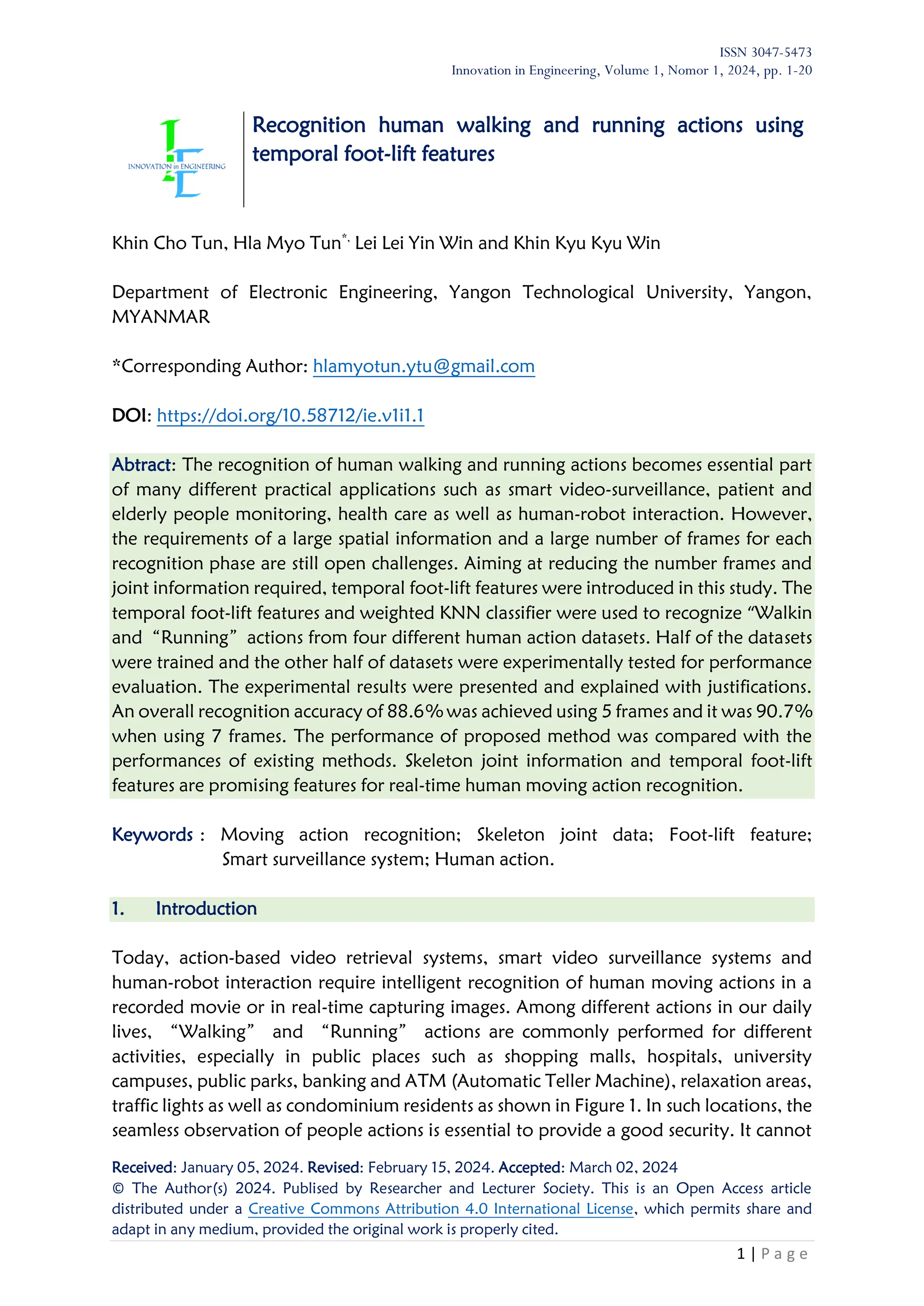
The number of trained data and test data are shown in Table 2. In KARD dataset and
G3D dataset, there are 10 different subjects (persons) who repeat each action 3 times.
Then, UTKinet contains dataset for 10 subjects (persons) who repeat each action 2 times.
In CMUMoCap dataset, 5 subjects performed “Running” action and 29 subjects
performed “Walking” action. However, only “Walking” actions of some subjects
were used. “Running” actions are variable only from G3D dataset and CMUMoCap
dataset. Both female and male actors are included in performing actions. The](https://image.slidesharecdn.com/1-articletext-29-5-10-20240513-250629181353-e546d411/75/Recognition-human-walking-and-running-actions-using-temporal-foot-lift-features-10-2048.jpg)
![ISSN 3047-5473
Innovation in Engineering, Volume 1, Nomor 1, 2024, pp. 1-20
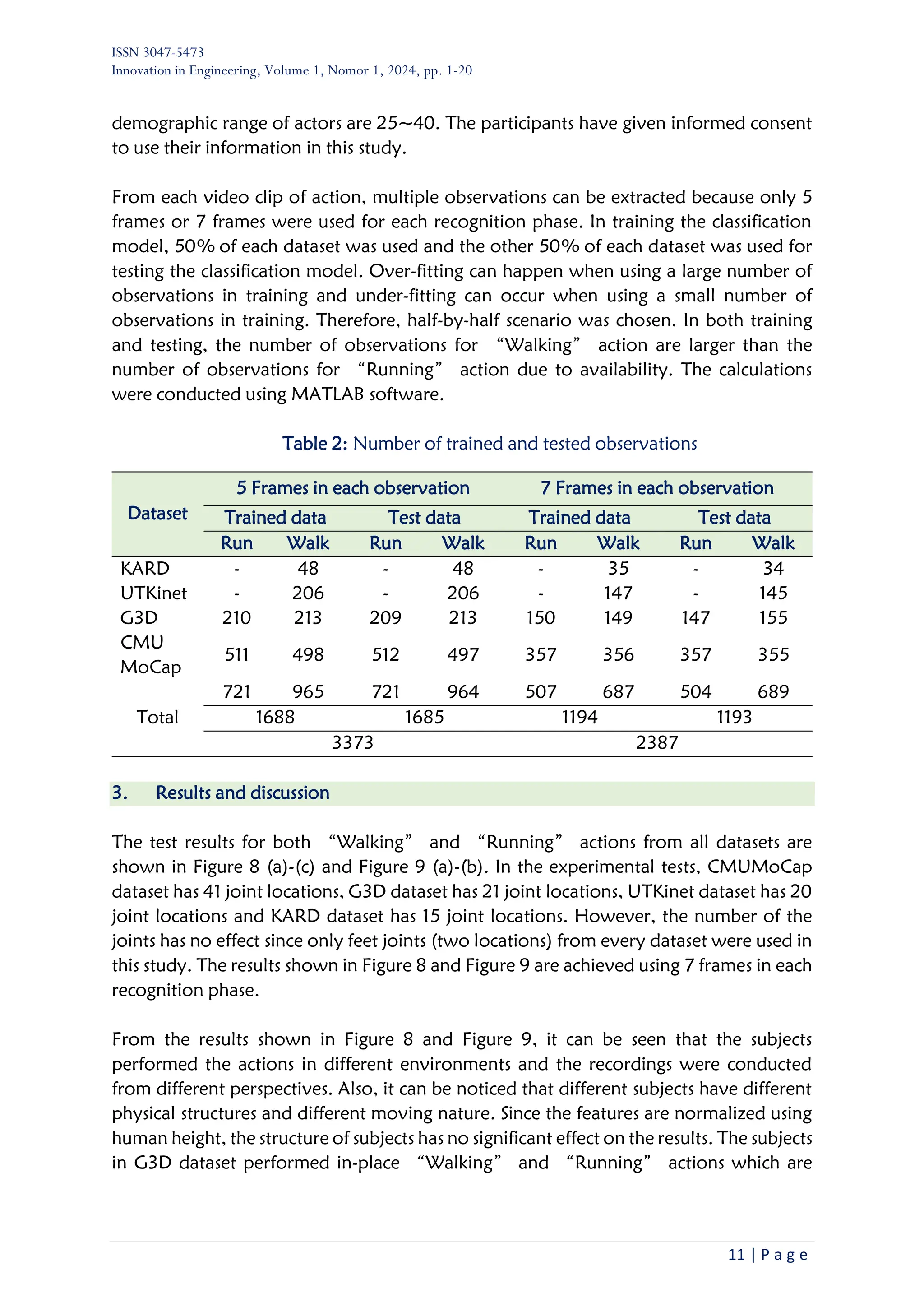
15 | P a g e
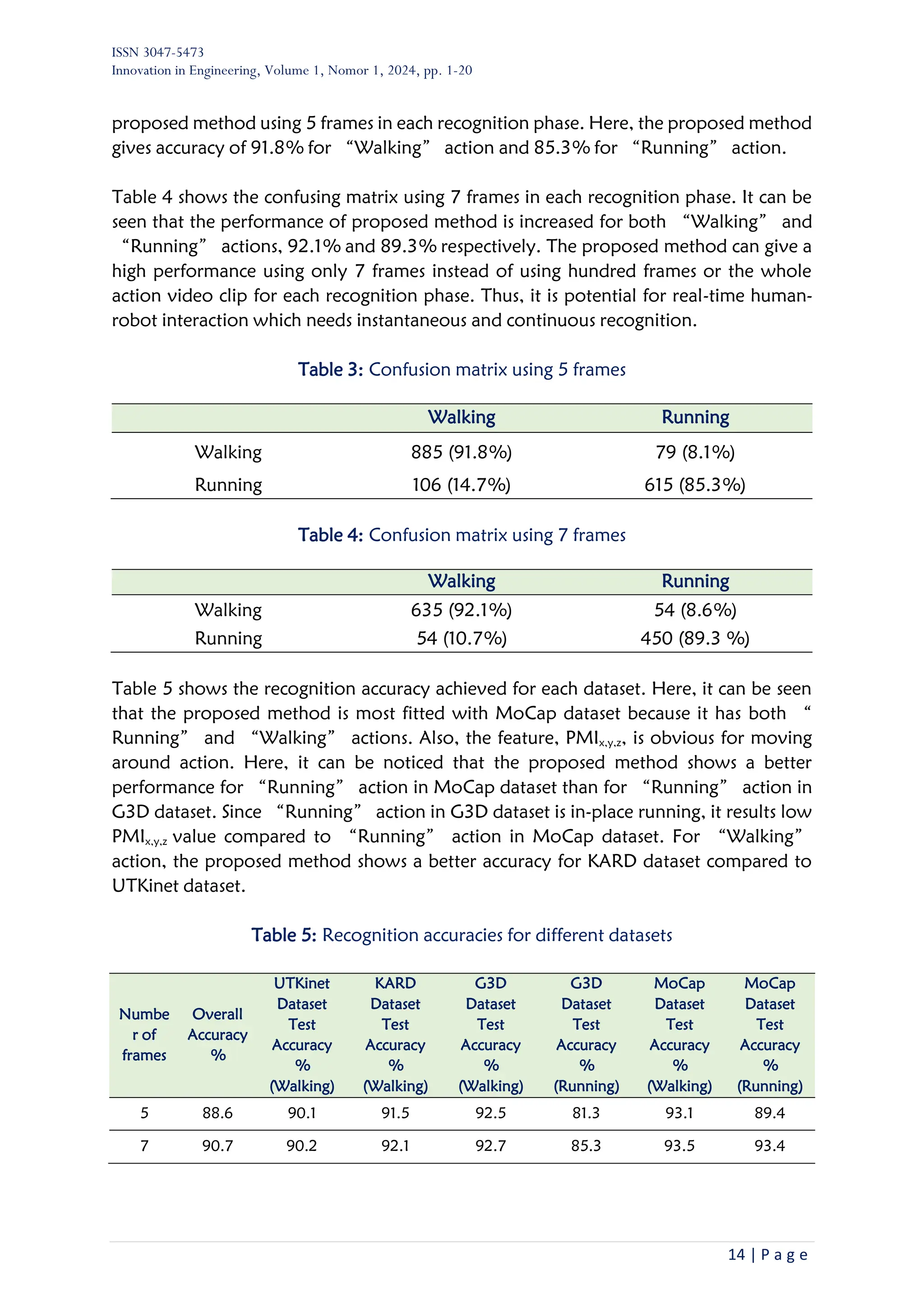
Table 6: Comparison with state-of-the-art-methods
Method Dataset used
Joint
information
used
Number of
frames used
Action
Accuracy
(%)
[6] KTH Datasets
The whole
silhouette
60
Walking,
Jogging
Running
92.0
[22]
Weizmann,
KTH Datasets
The whole
silhouette
7
Walking
and
Running
98.5
[22]
Weizmann,
KTH Datasets
The whole
silhouette
10
Walking
and
Running
99.6
[29] KTH Datasets
The whole
silhouette
The whole
video clip
Walking
and
Running
93.8
[30]
Weizmann
Datasets
The whole
silhouette
10
Walking
and
Running
99.6
[16]
NTU RGB+D
dataset
12, 15, 39 125 Walking 100.0
Ours
KARD,
UTKinet,
G3D, MoCap
2 7
Walking
and
Running
90.7
Table 6 shows the performance of proposed method comparing with existing methods.
Although most existing methods showed impressive accuracies, they still have challenges
in joint information and frame requirements. It can be seen that proposed methods in
[31], [22], [29], [30] were based on RGB images and the information of the whole
silhouette. Thus, the existing method could result in a high uncertainty in occluded
conditions. Meanwhile the proposed method in this study requires only two (feet) joint
information.
In other works [31], [29] [16] the number of frames required is 60, 125 or the whole
video clip. In [22] and [30] the number of frames required is 7 to 10 to obtain an accuracy
of up to 99.6%. However, it was based on the whole silhouette information. Also, the
tested data are from only two datasets. Although the proposed method showed a little
lower than existing methods, requirements of only feet information and very small
number of frames are preferable points of proposed method. It is very potential to be
utilized in real-field applications. The other advantage of the proposed method is that it
still works with in-place walking or running which are rarely considered in previous](https://image.slidesharecdn.com/1-articletext-29-5-10-20240513-250629181353-e546d411/75/Recognition-human-walking-and-running-actions-using-temporal-foot-lift-features-15-2048.jpg)
![ISSN 3047-5473
Innovation in Engineering, Volume 1, Nomor 1, 2024, pp. 1-20
17 | P a g e
Acknowledgements
The authors would like to express their sincere thanks to all research partners from both
who have developed and shared valuable datasets for the further studies including
current study related to human action recognition.
Competing interest
The authors declare that they have no known competing financial interests or personal
relationships that could have appeared to influence the work reported in this paper.
References
[1] M. Kashef, A. Visvizi, and O. Troisi, “Smart city as a smart service system: Human-
computer interaction and smart city surveillance systems,” Comput Human Behav, vol.
124, pp. 1–14, Nov. 2021, https://doi.org/10.1016/j.chb.2021.106923
[2] G. Johansson, “Visual perception of biological motion and a model for its analysis",”
Percept Psychophys, vol. 14, no. 2, pp. 201–211, Jun. 1973.
[3] H. Su and F.-G. Huang, “Human Gait Recognition Based on Motion Analysis,” in
International Conference on Machine Learning and Cybernetics, Guangzhou, China: IEEE,
Aug. 2005, pp. 4464–4468. https://doi.org/10.1109/ICMLC.2005.1527725
[4] O. Masoud and N. Papanikolopoulos, “A method for human action recognition,”
Image Vis Comput, vol. 21, no. 8, pp. 729–743, Aug. 2003,
https://doi.org/10.1016/S0262-8856(03)00068-4
[5] N. Käse, M. Babaee, and G. Rigoll, “Multi-view human activity recognition using motion
frequency,” in IEEE International Conference on Image Processing (ICIP), Beijing, China:
IEEE, Sep. 2017, pp. 3963–3967. https://doi.org/10.1109/ICIP.2017.8297026
[6] P. Fihl and T. B., “Recognizing Human Gait Types,” Robot Vision, pp. 183–208, Mar.
2010, https://doi.org/10.5772/9293
[7] T. Ahmad, S. T. H. Rizvi, and N. Kanwal, “Transforming spatio-temporal self-attention
using action embedding for skeleton-based action recognition,” J Vis Commun Image
Represent, vol. 95, pp. 1–11, Sep. 2023, https://doi.org/10.1016/j.jvcir.2023.103892
[8] Y. Hbali, S. Hbali, L. Ballihi, and M. Sadgal, “Skeleton-based human activity recognition
for elderly monitoring systems,” IET Computer Vision, vol. 12, no. 1, pp. 16–26, Feb.
2018, https://doi.org/10.1049/iet-cvi.2017.0062
[9] X. Jiang, K. Xu, and T. Sun, “Action Recognition Scheme Based on Skeleton
Representation with DS-LSTM Network,” IEEE Transactions on Circuits and Systems for
Video Technology, vol. 30, no. 7, pp. 2129–2140, Jul. 2020,
https://doi.org/10.1109/TCSVT.2019.2914137
[10] A. F. Bavil, H. Damirchi, and H. D. Taghirad, “Action Capsules: Human Skeleton Action
Recognition,” Computer Vision and Image Understanding, vol. 223, pp. 1–11, Aug.
2023, https://doi.org/10.1016/j.cviu.2023.103722
[11] M. A. R. Ahad, M. Ahmed, A. Das Antar, Y. Makihara, and Y. Yagi, “Action recognition
using kinematics posture feature on 3D skeleton joint locations,” Pattern Recognit Lett,
vol. 145, pp. 216–224, May 2021, https://doi.org/10.1016/j.patrec.2021.02.013](https://image.slidesharecdn.com/1-articletext-29-5-10-20240513-250629181353-e546d411/75/Recognition-human-walking-and-running-actions-using-temporal-foot-lift-features-17-2048.jpg)
![ISSN 3047-5473
Innovation in Engineering, Volume 1, Nomor 1, 2024, pp. 1-20
18 | P a g e
[12] F. Khezerlou, A. Baradarani, and M. A. Balafar, “A Convolutional Autoencoder Model
with Weighted Multi-Scale Attention Modules for 3D Skeleton-Based Action Recognition,
” J Vis Commun Image Represent, vol. 92, pp. 1–14, Apr. 2022.
[13] S. Ghazal, U. S. Khan, M. M. Saleem, N. Rashid, and J. Iqbal, “Human activity
recognition using 2D skeleton data and supervised machine learning,” IET Image Process,
vol. 13, no. 13, pp. 2572–2578, Nov. 2019, https://doi.org/10.1049/iet-ipr.2019.0030
[14] J. Kim, G. Li, I. Yun, C. Jung, and J. Kim, “Weakly-supervised temporal attention 3D
network for human action recognition,” Pattern Recognit, vol. 119, pp. 1–10, Nov. 2021,
https://doi.org/10.1016/j.patcog.2021.108068
[15] W. Peng, X. Hong, and G. Zhao, “Tripool: Graph triplet pooling for 3D skeleton-based
action recognition,” Pattern Recognit, vol. 115, pp. 1–12, Jul. 2021,
https://doi.org/10.1016/j.patcog.2021.107921
[16] M. Terreran, L. Barcellona, and S. Ghidoni, “A general skeleton-based action and gesture
recognition framework for human–robot collaboration,” Rob Auton Syst, vol. 170, pp.
1–14, Dec. 2023, https://doi.org/10.1016/j.robot.2023.104523
[17] Q. Xu, W. Zheng, Y. Song, C. Zhang, X. Yuan, and Y. Li, “Scene image and human
skeleton-based dual-stream human action recognition,” Pattern Recognit Lett, vol. 148,
pp. 136–145, Aug. 2021, https://doi.org/10.1016/j.patrec.2021.06.003
[18] C. Plizzari, M. Cannici, and M. Matteucci, “Skeleton-based action recognition via spatial
and temporal transformer networks,” Computer Vision and Image Understanding, vol.
208–209, pp. 1–10, Jul. 2021, https://doi.org/10.1016/j.cviu.2021.103219
[19] Q. Ye, Z. Tan, and Y. Zhang, “Human action recognition method based on Motion
Excitation and Temporal Aggregation module,” Heliyon, vol. 8, no. 11, pp. 1–12, Nov.
2022, https://doi.org/10.1016/j.heliyon.2022.e11401
[20] O. C. Kurban, N. Calik, and T. Yildirim, “Human and action recognition using adaptive
energy images,” Pattern Recognit, vol. 127, pp. 1–23, Jul. 2022,
https://doi.org/10.1016/j.patcog.2022.108621
[21] J. Lin, Z. Mu, T. Zhao, H. Zhang, X. Yang, and P. Zhao, “Action density based frame
sampling for human action recognition in videos,” J Vis Commun Image Represent, vol.
90, pp. 1–7, Feb. 2023, https://doi.org/10.1016/j.jvcir.2022.103740
[22] K. Schindler, E. Zürich, L. Van Gool, and K. Leuven, “Action Snippets: How many frames
does human action recognition require?,” in IEEE Conference on Computer Vision and
Pattern Recognition, Anchorage, AK, USA: IEEE, Jun. 2008, pp. 1–8. doi:
https://doi.org/10.1109/CVPR.2008.4587730
[23] M. B. Shaikh and D. Chai, “Rgb-d data-based action recognition: A review,” Sensors,
vol. 21, no. 12, pp. 1–25, Jun. 2021, https://doi.org/10.3390/s21124246
[24] S. Gaglio, G. Lo Re, and M. Morana, “Human Activity Recognition Process Using 3-D
Posture Data,” IEEE Trans Hum Mach Syst, vol. 45, no. 5, pp. 586–597, Oct. 2015,
https://doi.org/10.1109/THMS.2014.2377111
[25] V. Bloom, V. Argyriou, and D. Makris, “Hierarchical Transfer Learning for Online
Recognition of Compound Actions,” Computer Vision and Image Understanding, vol.
144, pp. 62–72, Mar. 2015, https://doi.org/10.1016/j.cviu.2015.12.001
[26] Lu Xia, Chia-Chih Chen, and J. K. Aggarwal, “View Invariant Human Action Recognition
Using Histograms of 3D Joints ,” in IEEE Computer Society Conference on Computer
Vision and Pattern Recognition Workshops, Providence, RI: IEEE, Jul. 2012, pp. 20–27.
https://doi.org/10.1109/CVPRW.2012.6239233](https://image.slidesharecdn.com/1-articletext-29-5-10-20240513-250629181353-e546d411/75/Recognition-human-walking-and-running-actions-using-temporal-foot-lift-features-18-2048.jpg)
![ISSN 3047-5473
Innovation in Engineering, Volume 1, Nomor 1, 2024, pp. 1-20
19 | P a g e
[27] re3data.org, “CMU Graphics Lab Motion Capture Database,” re3data.org - Registry of
Research Data Repositories. Accessed: Apr. 01, 2024. [Online]. Available:
http://mocap.cs.cmu.edu/
[28] J. H. Yoo and M. S. Nixon, “Automated markerless analysis of human gait motion for
recognition and classification,” ETRI Journal, vol. 33, no. 2, pp. 259–266, Apr. 2011,
https://doi.org/10.4218/etrij.11.1510.0068
[29] H. Jhuang, T. Serre, and L. Wolf, “A Biologically Inspired System for Action Recognition,
” in IEEE 11th International Conference on Computer Vision, Rio de Janeiro, Brazil: IEEE,
Oct. 2007, pp. 1–8.
[30] M. Blank, L. Gorelick, E. Shechtman, M. Irani, and R. Basri, “Actions as Space-Time
Shapes,” IEEE Trans Pattern Anal Mach Intell, vol. 29, no. 12, pp. 1395–1402, Dec. 2007,
https://doi.org/10.1109/TPAMI.2007.70711
[31] P. Fihl and T. B., “Recognizing Human Gait Types,” in Robot Vision, InTech, 2010.
https://doi.org/ 10.5772/9293
Nomenclature
C Class
d Euclidean distance
E Error (Difference)
F Feature
K Number of nearest neighbours
n Number of frames
H Height of human
PMI Pixel motion feature
R Normalized foot-lift
w Weight
x X-coordinate
y Y-coordinate
z Z-coordinate
Subscripts
f foot
h higher
i, j ith
,jth
l lower
p moving path,
pr predicted
m mean
max maximum
rms root-mean-square
trained trained
tested tested
x x-direction](https://image.slidesharecdn.com/1-articletext-29-5-10-20240513-250629181353-e546d411/75/Recognition-human-walking-and-running-actions-using-temporal-foot-lift-features-19-2048.jpg)


![[20240812_LabSeminar_Huy]Spatio-Temporal Fusion for Human Action Recognition ...](https://cdn.slidesharecdn.com/ss_thumbnails/20240812labseminarhuyjtformer-240820045816-732e4933-thumbnail.jpg?width=640&height=640&fit=bounds)