The document summarizes the aim, theory, procedure, and observations of an experiment to study the decay of charge in an RC circuit and determine the RC time constant. The key points are:
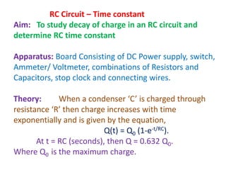
1) The experiment aims to study how the charge in a capacitor decays over time when connected to a resistor in a circuit, and determine the RC time constant.
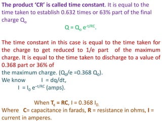
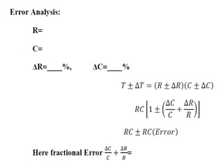
2) Theoretically, the charge decays exponentially over time according to the equation Q(t) = Q0(1-e-t/RC). The time constant RC is the time taken for the charge to reduce to 36.8% of the initial value.
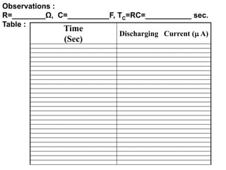
3) The procedure involves charging a capacitor through a resistor, measuring