
Recommended
Recommended
More Related Content
What's hot
What's hot (10)
Similar to Raspberry PI Based Home Appliances Control System using Microcontroller
Similar to Raspberry PI Based Home Appliances Control System using Microcontroller (20)
More from ijtsrd
More from ijtsrd (20)
Recently uploaded
Recently uploaded (20)
Raspberry PI Based Home Appliances Control System using Microcontroller
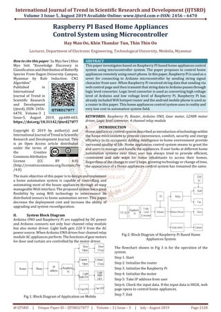
- 1. International Journal of Trend in Scientific Research and Development (IJTSRD) Volume 3 Issue 5, August 2019 Available Online: www.ijtsrd.com e-ISSN: 2456 – 6470 @ IJTSRD | Unique Paper ID – IJTSRD27877 | Volume – 3 | Issue – 5 | July - August 2019 Page 2128 Raspberry PI Based Home Appliances Control System using Microcontroller Hay Man Oo, Khin Thandar Tun, Thin Thin Oo Lecturer, Department of Electronic Engineering, Technological University, Meiktila, Myanmar How to cite this paper: Su Myo Swe|Khin Myo Sett "Knowledge Discovery in Classification andDistributionofButterfly Species From Dagon University Campus, Myanmar by Rule Induction: CN2 Algorithm" Published in International Journal of Trend in Scientific Research and Development (ijtsrd), ISSN: 2456- 6470, Volume-3 | Issue-5, August 2019, pp.600-603, https://doi.org/10.31142/ijtsrd27877 Copyright © 2019 by author(s) and International Journal ofTrend inScientific Research and Development Journal. This is an Open Access article distributed under the terms of the Creative Commons Attribution License (CC BY 4.0) (http://creativecommons.org/licenses/by /4.0) . ABSTRACT This paper investigates based on Raspberry PI based home appliances control system using microcontroller system. The paper proposes to control home appliances remotely using smart phone.Inthis paper,RaspberryPi is used as a sever for connecting to Arduino microcontroller by sending string signal character from user. When Raspberry Pi received string data that sending via web control page and then transmit that string data toArduinopasses through logic level converter. Logic level converter is used as converting high voltage level of Arduino and low voltage level of Raspberry Pi. Raspberry Pi has already included Wifi hotspot router and the android mobile phone is used as a router in this paper. This home appliances control system uses in realityand very low cost in automation system field. KEYWORDS: Raspberry Pi, Router, Arduino UNO, Gear motor, L298N motor driver, Logic level converter, 4 channel relay module I. INTRODUCTION Home appliances control systemdescribedas introductionoftechnologywithin the home environment to provide convenience, comfort, security and energy efficiency to its occupants. Adding intelligence to home environment provide increased quality of life. Home appliances control system means to grant the end users to manage and handle the appliances. If user looks at different home automation systems over time, user has always tried to provide efficient, convenient and safe ways for home inhabitants to access their homes. Regardless of the change in user’s hope, growing technology or change of time, the appearance of a Home appliances control system has remained the same. The main objective of this paper is to design and implement a home automation system is capable of controlling and automating most of the house appliances through an easy manageable Web interface. The proposed systemhas a great flexibility by using Wifi technology to interconnect its distributed sensors to home automation server. This paper decrease the deployment cost and increase the ability of upgrading and system reconfiguration. II. System Block Diagram Arduino UNO and Raspberry Pi are supplied by DC power and Arduino connects not only four channel relay module but also motor driver. Light bulb gets 220 V from the AC power source. When Arduino UNO drives four channel relay module AC appliances perform.Thefunctionsofgear motors for door and curtain are controlled by the motor driver. Fig 1: Block Diagram of Application on Mobile Fig 2: Block Diagram of Raspberry Pi Based Home Appliances System The flowchart shown in Fig 3 is for the operation of the system. Step 1: Start Step 2: Initialize the router Step 3: Initialize the Raspberry Pi Step 4: Initialize the motor Step 5: Take IP address from user Step 6: Check the input data. If the input data is HIGH, web page opens to control home appliances. Step 7: Exit IJTSRD27877
- 2. International Journal of Trend in Scientific Research and Development (IJTSRD) @ www.ijtsrd.com eISSN: 2456-6470 @ IJTSRD | Unique Paper ID – IJTSRD27877 | Volume – 3 | Issue – 5 | July - August 2019 Page 2129 Start Initialize the router Initialize the Raspberry Pi Initialize the motor Take IP address from user Open web page stored on Apache web server of Raspberry Pi Door Open / Close Curtin Open / Close Light bulb ON / OFF Fan ON / OFF Exit YesIs the input data HIGH Yes No Fig 3: Overall System Flowchart III. Implementation A. Software Implementation Software Implementation for Door Open The programming language is written as the simplest form so that it is nothing to have any problem to understand. The setup function for the door open is declared pin 12, pin 13 and for the motor is declared pin 9. Pin 12 is HIGH and pin 13 is LOW that means the door is opened by using digitalWrite. And also pin 9 is 100 the door is opened by using analogWrite. And delay time is three seconds. digitalWrite (12, HIGH); digitalWrite (13, LOW); analogWrite ( 9, Speed); delay (3800); digitalWrite (12,LOW); digitalWrite (13,LOW); analogWriite (9,0); Software Implementation for Door Close The programming language for the door closeis verysimple. The setup function for the door close is declared pin12, pin 13 and for the motor is declared pin 9. Pin 12 is LOW andpin 13 is HIGH that means the door is closed by using digital Write. And also pin 9 is 100 the door is closed by using analog Write. And delay time is three seconds. Digital Write (12, LOW); Digital Write (13, HIGH); Analog Write ( 9, Speed); Delay (door Delay); Digital Write (12,LOW); Digital Write (13,LOW); analogWriite (9,0); Software Implementation for Curtain Open The programming language for the curtain open is very simple. The setup function for the curtain open is declared pin 4, pin 5 and for the motor is declared pin 10. Pin 4 is LOW and pin 5 is HIGH that means the curtain is opened by using digitalWrite. And also pin 10 is 100 the curtain is opened by using analogWrite.Anddelaytimeis twoseconds. digitalWrite (4, LOW); digitalWrite (5, HIGH); analogWrite ( 10, Speed); delay (curtainDelay); digitalWrite (4,LOW); digitalWrite (5,LOW); analogWriite (10,0); Software Implementation for Curtain Close The programming language for the curtain close is very simple. The setup function for the curtain close is declared pin 4, pin 5 and for the motor is declared pin 10. Pin 4 is HIGH and pin 5 is LOW that means the curtain is closed by using digitalWrite. And also pin 10 is 100 the curtain is closed by using analogWrite. And delay time is two seconds. digitalWrite (4, HIGH); digitalWrite (5, LOW); analogWrite ( 10, Speed); delay (curtainDelay); digitalWrite (4,LOW); digitalWrite (5,LOW); analogWriite (10,0); Software Implementation for Light Bulb Open and Light Bulb Close The programming language for the light bulb open and light bulb close are very simple. The setup function for the light bulb is declared pin 8.Pin 8 is HIGH that means the light bulb is opened by using digitalWrite. And also pin 8 is LOW, the light bulb is closed by using digitalWrite. case “e” :digitalWrite (8, HIGH ); break; case “f” : digitalWrite (8,LOW ); break; Software Implementation for Fan Open and Fan Close The programming language for the fan open and fan close are very simple. The setup function for the light bulb is declared pin 7.Pin 7 is HIGH that means the fan is opened by using digitalWrite. And also pin 7 is LOW; thefanis closedby using digitalWrite. case “g” :digitalWrite (7, HIGH ); break; case “h” : digitalWrite (7,LOW ); break;
- 3. International Journal of Trend in Scientific Research and Development (IJTSRD) @ www.ijtsrd.com eISSN: 2456-6470 @ IJTSRD | Unique Paper ID – IJTSRD27877 | Volume – 3 | Issue – 5 | July - August 2019 Page 2130 B. Implementation by Hardware Fig 4: Overall Circuit Diagram of the System The hardware design ofRaspberryPi basedhomeappliances control system using microcontroller is shown in Fig 4. Pin A0 of the logical level converter is connected to the pin D2 of the Arduino board, pin A1 of the logical level converter is connected to the pin D3 of the microcontroller and VccB of the logical level converter is connected to the 5 V pin out of the microcontroller. Pin B0 of the logical level converter is connected to the pin 15 (GPIO) of the Raspberry Pi and pin B1 of the logical level converter is connected to the pin 14 (GPIO) of the Raspberry Pi. VccA of the logical level converter is connected to the 3.3 V of the Raspberry Pi. The GND pin of the logical level converter is connected to the GND pin of the Raspberry Pi. The Raspberry Pi issuppliedby 5 V power adaptor. The input pin 1, pin 2, pin 3, pin 4 of the L298N motor driver are connected pin D4, D5, D12, D13 of the microcontroller. The Enable pin A and Enable pin B of the L298N motor driver are connectedtothepinD9, pinD10 of the microcontroller. Pin 7 of the microcontroller is connected to the relay 2 and pin 8 of the microcontroller is connected to the relay 1. The GND pins of both microcontroller and L298N motor driver are connected to the GND pin of the logical level converter. The 5 V pin and 12 V pin are connected to the 5 V pin and VIN of the microcontroller. The output pin 1 and output pin 2 of the L298N motor driver are connected to the gear motor 1and gear motor 2. The output pin 3 and output pin 4 of the L298N motor driver are connected to the gear motor 3 and gear motor 4. Relay 1 is connected to the fan and fan is supplied 12 V power adapter. Relay 2 is connected to the light bulb and light bulb is supplied by 220 V. Theuserinsets IP address from smart phone and gets open web pages stored on Apache Web server and then operates door open, door close, curtain open, curtain close, light bulb open, light bulb close, fan open and fan close. IV. Results The user inserts the IP address and the user seecontrol page in browser. Fig 5: Control Web Page Result for Door Open If pin 12 is HIGH and pin 13 is LOW, the door is opened. Fig 6: Result for the Door Open Result for Door Close If pin 12 is LOW and pin 13 is HIGH, the door is closed. Fig 7: Result for the Door Close Result for Curtain Open If pin 4 is LOW and pin 5 is HIGH, the curtain is opened. Fig 8: Result for the Curtain Open
- 4. International Journal of Trend in Scientific Research and Development (IJTSRD) @ www.ijtsrd.com eISSN: 2456-6470 @ IJTSRD | Unique Paper ID – IJTSRD27877 | Volume – 3 | Issue – 5 | July - August 2019 Page 2131 Result for Curtain Close If pin 4 is HIGH and pin 5 is LOW, the curtain is closed. Fig 9: Result for the Curtain Close Result for Light Bulb Open If pin 8 is HIGH, the light bulb is opened. Fig 10: Result for the Light Bulb Open Result for Light Bulb Close If pin 8 is LOW, the light bulb is closed. Fig 11: Result for the Light Bulb Close Results for Fan Open If pin 7 is HIGH, the fan is opened. Fig 12: Result for the Fan Open Results for Fan Close If pin 7 is LOW, the fan is closed. Fig 13: Result for the Fan Close V. Conclusion The devices produced enable the user to control the appliances using pre existing devices such as the smart phone or home computer. The interfaces are intuitive and easy to use and provide the user with a more accessible interface then those found in thehome.Thedevices alsovery easy to integrate into existingapplications and requireonly a small amount of expertise to install. Userresearchshows the many types of applications for implementing home automation and the applications are not limited to those discussed in this paper. The technology used in a wide variety of applications that require the use of sensors and appliances. This paper successfully designed a system that communicates with a mobile device suchas a smartphone or laptop via Raspberry Pi to applications that benefitfromthis work. REFERENCES [1] Ms. Akanksha Rajendra Surve, Mr. Sampat Vaidya. “Research Paper on Android based Home automation using Raspberry Pi”. International Journal of Advance Engineering and Research Development (Volume 4, Issue 6) (June 2017). [2] Neha Malik, Yogita Bodwade. International Journal of Advance Research in computer and communication Engineering. (Volume 6, Issue 3) (March 2017) [3] Vaishnavi S. Gunge. Walchand Institude of Technology, Solapur. International Journal of Computer Applications National Seminar on Recent Trends in Data Mining (RTDM 2016) [4] Monika M Patel, Mehul A Jajal and Dixita B Vataliya. Home automation using Raspberry Pi. International Journal of Innovative and Emerging Research in Engineering (Volume 2, Issue 3) (2015) [5] M. P. Sathish, Dr. S. A. K. Jilani, Asst. Professor. Home Automation through E-mail using Raspberry Pi. International Journal of Advanced Research in Electronics and communication Engineering. (Volume 4, Issue 9) (September 2015) [6] Allison M Okamura, Stanford University: Arduino Programming language (2014) [7] Md. Nasimuzzaman Chowdhury, Md. Shiblee Nooman and Srijon Sarker. Access control of Door and Home security by RaspberryPi ThroughInternet.Internationl Journal of Scientific and Engineering Research (Volume4) (October 2013)