Quantum Physics AText For Graduate Students
download
https://ebookbell.com/product/quantum-physics-a-text-for-
graduate-students-1208050
Explore and download more ebooks at ebookbell.com
2.
Here are somerecommended products that we believe you will be
interested in. You can click the link to download.
Quantum Physics A Text For Graduate Students Roger G Newton
https://ebookbell.com/product/quantum-physics-a-text-for-graduate-
students-roger-g-newton-56348364
Quantum Physics A Text For Graduate Students Newton
https://ebookbell.com/product/quantum-physics-a-text-for-graduate-
students-newton-1085106
Quantum Physics A Text For Graduate Students 1st Edition Roger G
Newton
https://ebookbell.com/product/quantum-physics-a-text-for-graduate-
students-1st-edition-roger-g-newton-927770
Coherent Quantum Physics A Reinterpretation Of The Tradition Texts And
Monographs In Theoretical Physics 1st Edition Arnold Neumaier
https://ebookbell.com/product/coherent-quantum-physics-a-
reinterpretation-of-the-tradition-texts-and-monographs-in-theoretical-
physics-1st-edition-arnold-neumaier-11297558
3.
Quantum Mechanics AModern And Concise Introductory Course Advanced
Texts In Physics 2nd Daniel Bes
https://ebookbell.com/product/quantum-mechanics-a-modern-and-concise-
introductory-course-advanced-texts-in-physics-2nd-daniel-bes-2163346
Introduction To The Theory Of Quantum Information Processing Graduate
Texts In Physics 2013th Edition Bergou
https://ebookbell.com/product/introduction-to-the-theory-of-quantum-
information-processing-graduate-texts-in-physics-2013th-edition-
bergou-56238956
Manybody Quantum Theory In Condensed Matter Physics An Introduction
Oxford Graduate Texts Henrik Bruus
https://ebookbell.com/product/manybody-quantum-theory-in-condensed-
matter-physics-an-introduction-oxford-graduate-texts-henrik-
bruus-36682828
Quantum Physics A Fundamental Approach To Modern Physics First John
Townsend
https://ebookbell.com/product/quantum-physics-a-fundamental-approach-
to-modern-physics-first-john-townsend-2540802
Quantum Physics A Beginners Guide Alastair I M Rae
https://ebookbell.com/product/quantum-physics-a-beginners-guide-
alastair-i-m-rae-4120696
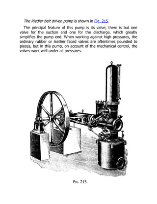
The Riedler beltdriven pump is shown in Fig. 215.
The principal feature of this pump is its valve; there is but one
valve for the suction and one for the discharge, which greatly
simplifies the pump end. When working against high pressures, the
ordinary rubber or leather faced valves are oftentimes pounded to
pieces, but in this pump, on account of the mechanical control, the
valves work well under all pressures.
Fig. 215.
7.
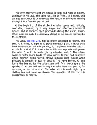
This valve andvalve seat are circular in form, and made of bronze,
as shown in Fig. 216. The valve has a lift of from 1 to 2 inches, and
an area sufficiently large to reduce the velocity of the water flowing
through it to a few feet per second.
At the beginning of the stroke the valve opens automatically,
controlled, however, by a very simple and effective mechanical
device, and it remains open practically during the entire stroke.
When near the end, it is positively closed at the proper moment by
the controller.
This valve, see Fig. 216, may be briefly described as follows. The
seat, A, is turned to slip into its place in the pump and is made tight
by a round rubber hydraulic packing, B, in a groove near the bottom.
A spindle or stud, C, in the center of this seat supports and guides
the valve, D, which is made tight by a leather seal, E. The rubber
collar or buffer spring holds the valve above its seat, and this valve
unlike ordinary pump valves, always remains open except when
pressure is brought to bear to close it. The valve bonnet, G, also
forms the bearing for the valve stem with fork, which spans the
spindle, C, at one end and having the valve lever and pin, H, for
operating at the other end. The valve stem is made tight by a
stuffing-box and gland as shown. The operation of this valve is
substantially as follows.
8.
Fig. 216.
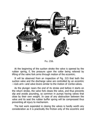
At thebeginning of the suction stroke the valve is opened by the
rubber spring, F, the pressure upon the collar being relieved by
lifting of the valve fork arms through motion of the eccentric.
It will be observed from an inspection of Fig. 215 that both the
suction valve and the discharge valve are controlled by an eccentric
—rock arm—and valve levers similar to the motion of Corliss valves.
As the plunger nears the end of its stroke and before it starts on
the return stroke, the valve fork closes the valve, and thus prevents
slip and avoids pounding, so common in pumps having valves that
close by their own weight. In case of any obstruction between the
valve and its seat the rubber buffer spring will be compressed thus
preventing all injury to mechanism.
The lost work expended in closing the valves is hardly worth any
consideration as it is practically the friction only of the eccentric and
9.
the members ofthe valve gearing, the bearings of which are all
small.
The motion for these valve gears is usually taken from an
eccentric on the main shaft.
The standard speed of the Riedler pumps is about 150 revolutions
per minute. Smaller pumps run even faster than this.
It may be desired to connect a pump directly to a high speed
electric motor or water wheel already installed. To meet these
conditions, a special design known as the Riedler Express pump, is
built.
The chief feature of this pump, is its suction valve. This valve is
concentric with, and outside of the plunger, and lifts in the opposite
direction to that of the plunger when on its suction stroke. At the
end of the suction stroke, the plunger presses the valve to its seat,
thus making it certain that the valve is seated when the plunger
starts on its delivery stroke, allowing practically no slip. A high air
suction chamber containing a column of water is placed immediately
before the suction valve, so it is certain that the pump will fill as the
plunger moves. Ordinarily the pump would not completely fill, owing
to the high speed of the plunger.
These pumps are also built with steam cylinders both of the plain
slide valve and Corliss designs.
ELECTRICITY AND ELECTRICALMACHINERY.
Each kind of power requires its own special machinery so
constructed and adapted as to utilize it; hence, to be serviceable to
mankind, electricity demands machinery suited to its nature; what
that is, will be indicated in the following few paragraphs.
Electricity is a name derived from the Greek word electron—
amber. It was discovered more than 2,000 years ago that amber
when rubbed with a Fox’s tail possessed the curious property of
attracting light bodies. It was discovered afterwards that this
property could be produced in a dry steam jet by friction, and in
A. D. 1600 or thereabouts, that glass, sealing-wax, etc., were also
affected by rubbing, producing electricity.
Whatever electricity is, it is impossible to say, but for the present it
is convenient to consider it as a kind of invisible something which
pervades all bodies. While the nature and source of electricity are a
mystery, and a constant challenge to the inquirer, many things about
it have become known—thus, it is positively assured that electricity
never manifests itself except when there is some mechanical
disturbance in ordinary matter, and every exhibition of electricity in
any of its multitudinous ways may always be traced back to a mass
of matter.
Note.—The great forces of the world are invisible and impalpable; we
cannot grasp or handle them; and though they are real enough, they have
the appearance of being very unreal. Electricity and gravity are as subtle
as they are mighty; they elude the eye and hand of the most skillful
philosopher. In view of this, it is well for the average man not to try to
fathom, too deeply, the science of either. To take the machines and
appliances as they are “on the market,” and to acquire the skill to operate
them, is the longest step toward the reason for doing it, and why the
desired results follow.
Electricity, it is also conceded, is without weight, and, while
electricity is, without doubt, one and the same, it is for convenience
sometimes classified according to its motion, as—
12.
1. Static electricity,or electricity at rest.
2. Current electricity, or electricity in motion.
3. Magnetism, or electricity in rotation.
4. Electricity in vibration.
Other useful divisions are into—
1. Frictional and
2. Dynamical,
And into—
1. Static, as the opposite of
2. Dynamic electricity.
There are still other definitions or divisions which are in every-day
use, such as “vitreous” electricity, “atmospheric” electricity,
“resinous” electricity, etc.
Static Electricity.—This is a term employed to define electricity
produced by friction. It is properly employed in the sense of a static
charge which shows itself by the attraction or repulsion between
charged bodies. When static electricity is discharged, it causes more
or less of a current, which shows itself by the passage of sparks or a
brush discharge; by a peculiar prickling sensation; by an unusual
smell due to its chemical effects; by heating the air or other
substances in its path; and sometimes in other ways.
Current Electricity.—This may be defined as the quantity of
electricity which passes through a conductor in a given time—or,
electricity in the act of being discharged, or electricity in motion.
An electric current manifests itself by heating the wire or
conductor, by causing a magnetic field around the conductor and by
causing chemical changes in a liquid through which it may pass.
Note.—Statics is that branch of mechanics which treats of the forces
which keep bodies at rest or in equilibrium. Dynamics treats of bodies in
motion. Hence static electricity is electricity at rest. The earth’s great store
of electricity is at rest or in equilibrium.
13.
Radiated electricity iselectricity in vibration. Where the current
oscillates or vibrates back and forth with extreme rapidity, it takes
the form of waves which are similar to waves of light.
Positive Electricity.—This term expresses the condition of the point
of an electrified body having the higher energy from which it flows
to a lower level. The sign which denotes this phase of electric
excitement is +; all electricity is either positive or,-, negative.
Negative Electricity.—This is the reverse condition to the above
and is expressed by the sign or symbol-. These two terms are used
in the same sense as hot and cold.
Atmospheric electricity is the free electricity of the air which is
almost always present in the atmosphere. Its exact cause is
unknown. The phenomena of atmospheric electricity are of two
kinds; there are the well-known manifestations of thunderstorms;
and there are the phenomena of continual slight electrification in the
air, best observed when the weather is fine; the aurora constitutes a
third branch of the subject.
Dynamic Electricity.—This term is used to define current electricity
to distinguish it from static electricity. This is the electricity produced
by the dynamo.
Frictional electricity is that produced by the friction of one
substance against another.
Resinous Electricity.—This is a term formerly used, in place of
negative electricity. The phrase originated in the well known fact that
a certain (negative) kind of electricity was produced by rubbing
rosin.
Vitreous electricity is a term, formerly used, to describe that kind
of electricity (positive) produced by rubbing glass.
Magneto-electricity is electricity in the form of currents flowing
along wires; it is electricity derived from the motion of magnets—
hence the name.
14.
Voltaic Electricity.—This iselectricity produced by the action of the
voltaic cell or battery.
Electricity itself is the same thing, or phase of energy, by whatever
source it is produced, and the foregoing definitions are given only as
a matter of convenience.
15.
ELECTRO-MOTIVE FORCE.
The termis employed to denote that which moves or tends to
move electricity from one place to another. For brevity it is written
E. M. F.; it is the result of the difference of potential, and
proportional to it. Just as in water pipes, a difference of level
produces a pressure, and the pressure produces a flow so soon as
the tap is turned on, so difference of potential produces electro-
motive force, and electro-motive force sets up a current so soon as a
circuit is completed for the electricity to flow through. Electro-motive
force, therefore, may often be conveniently expressed as a
difference of potential, and vice versa; but the reader must not
forget this distinction.
In ordinary acceptance among engineers and practical working
electricians, electro-motive force is considered as pressure and it is
measured in units called volts. The usual standard for testing and
comparison is a special form voltaic cell, called the Clark cell. This is
made with great care and composed of pure chemicals.
The term positive expresses the condition of the point having the
higher electric energy or pressure, and, negative, the lower relative
condition of the other point, and the current is forced through the
circuit by the (E. M. F.) electric pressure at the generator, just as a
current of steam is impelled through pipes by the generating
pressure at the steam-boiler.
Care must be taken not to confuse electro-motive force with
electric force or electric energy, when matter is moved by a magnet,
we speak rightly of magnetic force; when electricity moves matter,
we may speak of electric force. But, E. M. F. is quite a different
thing, not “force” at all, for it acts not on matter but on electricity,
and tends to move it.
16.
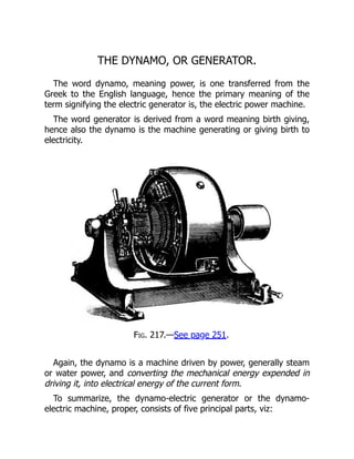
THE DYNAMO, ORGENERATOR.
The word dynamo, meaning power, is one transferred from the
Greek to the English language, hence the primary meaning of the
term signifying the electric generator is, the electric power machine.
The word generator is derived from a word meaning birth giving,
hence also the dynamo is the machine generating or giving birth to
electricity.
Fig. 217.—See page 251.
Again, the dynamo is a machine driven by power, generally steam
or water power, and converting the mechanical energy expended in
driving it, into electrical energy of the current form.
To summarize, the dynamo-electric generator or the dynamo-
electric machine, proper, consists of five principal parts, viz:
17.
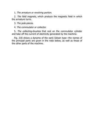
1. The armatureor revolving portion.
2. The field magnets, which produce the magnetic field in which
the armature turns.
3. The pole-pieces.
4. The commutator or collector.
5. The collecting-brushes that rest on the commutator cylinder
and take off the current of electricity generated by the machine.
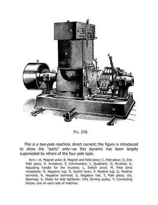
Fig. 218 shows a dynamo of the early Edison type—the names of
the principal parts are given in the note below, as well as those of
the other parts of the machine.
18.
Fig. 218.
This isa two-pole machine, direct current; the figure is introduced
to show the “parts” only—as this dynamo has been largely
superseded by others of the four pole type.
Note.—A, Magnet yoke; B, Magnet and field piece; C, Pole piece; D, Zinc
field piece; E, Armature; F, Commutator; I, Quadrant; JJ, Brushes; K,
Adjusting handle for the brushes; L, Switch pivot; M, Pilot lamp
receptacle; N, Negative lug; O, Switch lever; P, Positive lug; Q, Positive
terminal; R, Negative terminal; S, Negative rod; T, Pole piece; UU,
Bearings; X, Slides for belt tightener; VVV, Driving pulley; Y, Connecting
blocks, one on each side of machine.
19.
An electric motoris a machine for converting electrical energy into
mechanical energy; in other words it produces mechanical power
when supplied with an electric current; a certain amount of energy
must be expended in driving it; the intake of the machine is the term
used in defining the energy expended in driving it; the amount of
power it delivers to the machinery is denominated its out-put.
The difference between the out-put to the intake is the real
efficiency of the machine; it is well known that the total efficiency of
an electric distribution system, which may include several machines,
usually ranges from 75 to 80 per cent., at full load, and should not
under ordinary circumstances fall off more than say 5 per cent. at
one-third to half load; the efficiency of motors varies with their size,
while a one horse-power motor will, perhaps, have an efficiency of
60 per cent., a 100 horse-power may easily have an efficiency of 90
per cent. and the larger sizes even more.
The general and growing application of electric power to the
driving of all kinds of machinery including pumps makes the question
of motor driving one of the most important in the power field. For
many purposes, a single speed is sufficient, but for others, it is
imperative that the speed should be variable; and for still others,
though not absolutely necessary, a speed adjustment is very
desirable.
While the direct-current motor has been in this field so long that
its properties are well known and its possibilities fully developed, in
the operation of motors located in the immediate neighborhood of
the generator the alternating-current motor has marked advantages
where a large area of territory has to be covered and the conditions
are nearly uniform, that is to say—
Where the current has to be transmitted a long distance and the
load is approximately constant, the alternating system is preferred,
as it can be operated with small main lines or conductors. This
effects a saving in copper, over the direct system which requires
larger conductors.
20.
Fig. 219.
Fig. 220.
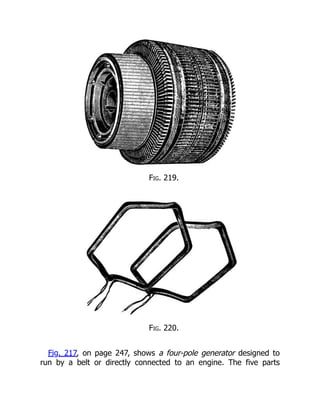
Fig.217, on page 247, shows a four-pole generator designed to
run by a belt or directly connected to an engine. The five parts
21.
named, as theprincipal parts of a dynamo, are all shown in the
figure. The machine is arranged ready to be bolted to the floor.
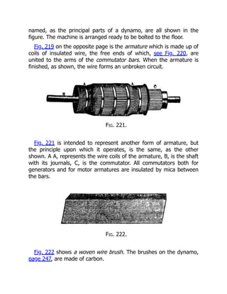
Fig. 219 on the opposite page is the armature which is made up of
coils of insulated wire, the free ends of which, see Fig. 220, are
united to the arms of the commutator bars. When the armature is
finished, as shown, the wire forms an unbroken circuit.
Fig. 221.
Fig. 221 is intended to represent another form of armature, but
the principle upon which it operates, is the same, as the other
shown. A A, represents the wire coils of the armature, B, is the shaft
with its journals, C, is the commutator. All commutators both for
generators and for motor armatures are insulated by mica between
the bars.
Fig. 222.
Fig. 222 shows a woven wire brush. The brushes on the dynamo,
page 247, are made of carbon.
22.
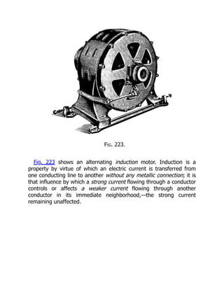
Fig. 223.
Fig. 223shows an alternating induction motor. Induction is a
property by virtue of which an electric current is transferred from
one conducting line to another without any metallic connection; it is
that influence by which a strong current flowing through a conductor
controls or affects a weaker current flowing through another
conductor in its immediate neighborhood,—the strong current
remaining unaffected.
23.
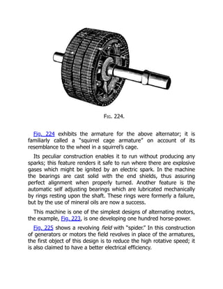
Fig. 224.
Fig. 224exhibits the armature for the above alternator; it is
familiarly called a “squirrel cage armature” on account of its
resemblance to the wheel in a squirrel’s cage.
Its peculiar construction enables it to run without producing any
sparks; this feature renders it safe to run where there are explosive
gases which might be ignited by an electric spark. In the machine
the bearings are cast solid with the end shields, thus assuring
perfect alignment when properly turned. Another feature is the
automatic self adjusting bearings which are lubricated mechanically
by rings resting upon the shaft. These rings were formerly a failure,
but by the use of mineral oils are now a success.
This machine is one of the simplest designs of alternating motors,
the example, Fig. 223, is one developing one hundred horse-power.
Fig. 225 shows a revolving field with “spider.” In this construction
of generators or motors the field revolves in place of the armatures,
the first object of this design is to reduce the high rotative speed; it
is also claimed to have a better electrical efficiency.
24.
Fig. 225.
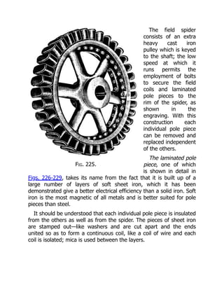
The fieldspider
consists of an extra
heavy cast iron
pulley which is keyed
to the shaft; the low
speed at which it
runs permits the
employment of bolts
to secure the field
coils and laminated
pole pieces to the
rim of the spider, as
shown in the
engraving. With this
construction each
individual pole piece
can be removed and
replaced independent
of the others.
The laminated pole
piece, one of which
is shown in detail in
Figs. 226-229, takes its name from the fact that it is built up of a
large number of layers of soft sheet iron, which it has been
demonstrated give a better electrical efficiency than a solid iron. Soft
iron is the most magnetic of all metals and is better suited for pole
pieces than steel.
It should be understood that each individual pole piece is insulated
from the others as well as from the spider. The pieces of sheet iron
are stamped out—like washers and are cut apart and the ends
united so as to form a continuous coil, like a coil of wire and each
coil is isolated; mica is used between the layers.
25.
Figs. 226-229.
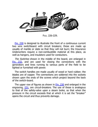
Fig. 230is designed to illustrate the front of a continuous current
two wire switchboard with circuit breakers; these are made up
usually of marble or slate so that they will not burn; the Insurance
Underwriters require a non-combustible material at this place, as
well as hangers, and insulators used for conductors.
The Switches shown in the middle of the board, are enlarged in
Fig. 232, and are used for closing the connections with the
generators and lines running to various parts of the field to be
lighted or furnished with power.
The switch handles are made usually of wood or hard rubber; the
blades are of copper. The connections are soldered into the sockets
shown upon the ends of the screws which project beyond the back
of the switch-board.
The upper row of figures as shown in Fig. 230 and enlarged in the
engraving, 231, are circuit-breakers. The use of these is analogous
to that of the safety-valve upon a steam boiler, so that when the
pressure in the circuit exceeds that at which it is set the “breaker”
opens the circuit and thus prevents damage.
26.
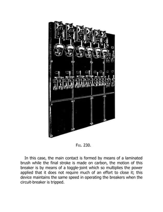
Fig. 230.
In thiscase, the main contact is formed by means of a laminated
brush while the final stroke is made on carbon, the motion of this
breaker is by means of a toggle-joint which so multiplies the power
applied that it does not require much of an effort to close it; this
device maintains the same speed in operating the breakers when the
circuit-breaker is tripped.
27.
Fig. 231.
Fig. 232.
ARheostat is a device for controlling the amount of electricity in a
conductor—by the insertion of coils of wire in a box—which may be
successively switched in or out of the main circuit by means of a
lever and button-switch. The best place to install a rheostat is on a
wall or post, as the resistance transforms a portion of the electric
energy into heat, which heat must be dispersed into the
atmosphere.
A transformer is an induction coil employed usually for lowering
electric pressure, but it may also be used for raising the same, in
which case it is sometimes called a booster. A compensator is a
transformer which works automatically.
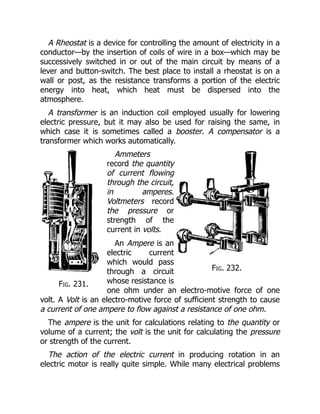
Ammeters
record the quantity
of current flowing
through the circuit,
in amperes.
Voltmeters record
the pressure or
strength of the
current in volts.
An Ampere is an
electric current
which would pass
through a circuit
whose resistance is
one ohm under an electro-motive force of one
volt. A Volt is an electro-motive force of sufficient strength to cause
a current of one ampere to flow against a resistance of one ohm.
The ampere is the unit for calculations relating to the quantity or
volume of a current; the volt is the unit for calculating the pressure
or strength of the current.
The action of the electric current in producing rotation in an
electric motor is really quite simple. While many electrical problems
28.
are comparatively complicated,the principal elements in the
operation of electric motors may be readily understood. The
fundamental fact in this connection is the relation between an
electric current and a magnet.
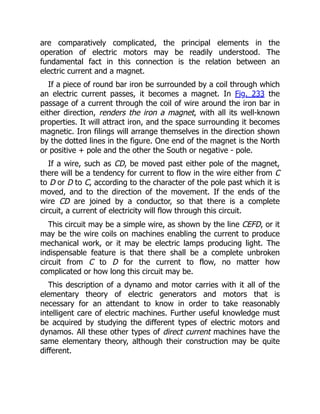
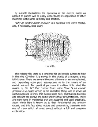
If a piece of round bar iron be surrounded by a coil through which
an electric current passes, it becomes a magnet. In Fig. 233 the
passage of a current through the coil of wire around the iron bar in
either direction, renders the iron a magnet, with all its well-known
properties. It will attract iron, and the space surrounding it becomes
magnetic. Iron filings will arrange themselves in the direction shown
by the dotted lines in the figure. One end of the magnet is the North
or positive + pole and the other the South or negative - pole.
If a wire, such as CD, be moved past either pole of the magnet,
there will be a tendency for current to flow in the wire either from C
to D or D to C, according to the character of the pole past which it is
moved, and to the direction of the movement. If the ends of the
wire CD are joined by a conductor, so that there is a complete
circuit, a current of electricity will flow through this circuit.
This circuit may be a simple wire, as shown by the line CEFD, or it
may be the wire coils on machines enabling the current to produce
mechanical work, or it may be electric lamps producing light. The
indispensable feature is that there shall be a complete unbroken
circuit from C to D for the current to flow, no matter how
complicated or how long this circuit may be.
This description of a dynamo and motor carries with it all of the
elementary theory of electric generators and motors that is
necessary for an attendant to know in order to take reasonably
intelligent care of electric machines. Further useful knowledge must
be acquired by studying the different types of electric motors and
dynamos. All these other types of direct current machines have the
same elementary theory, although their construction may be quite
different.
29.
By suitable illustrationsthe operation of the electric motor as
applied to pumps will be easily understood; its application to other
machines is the same in theory and practice.
“Why an electric motor revolves” is a question well worth careful,
and, if necessary, long study.
Fig. 233.
The reason why there is a tendency for an electric current to flow
in the wire CD when it is moved in the vicinity of a magnet is not
fully known. There are several theories, all more or less complicated,
and depending upon pure assumptions as to the nature of an
electric current. For practical purposes it matters little what the
reason is, the fact that current flows when there ts an electric
pressure in a closed circuit, is the important thing, and it serves all
useful purposes to know that current does flow, and that its direction
and amount are always the same under similar circumstances. There
are many facts in mechanics that are accepted and used practically,
about which little is known as to their fundamental and primary
causes, and this fact about motors and dynamos is, therefore, only
one of many which all must accept without a full and complete
explanation.
30.
The intensity ofthe electric pressure, or electro-motive force,
depends upon the velocity of revolution of the wire sections in the
armature and upon the strength of the magnets, and the quantity of
current depends upon the electro-motive force and upon the amount
of the resistance in the circuit. Other things being equal, the current,
flowing through a long small wire, or greater resistance, will be less
than through a short, thick wire, or a less resistance.
Having seen that when a wire is moved in the vicinity of a magnet
an electric pressure is produced which will cause a current to flow in
a closed circuit, one can easily conceive of many ways in which, by
combining magnets and wires so that there will be a relative motion
between them, a current of electricity may be generated. In order to
cause a continuous flow the relative motion must be continuous; and
if the current is to be uniform the motion must be uniform.
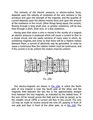
Fig. 234.
Two electro-magnets are shown in Fig. 234, in which the North
pole of one magnet is near the South pole of the other, and the
magnetic field between the two lies in the approximately straight
lines between the two magnets, as indicated by the dotted lines. If
the wire CD be moved across this field and its ends be joined, as by
the metallic circuit CEFD, a current will flow in this circuit. The wire
CD may be made to revolve around the wire EF, passing in front of
one pole and then in front of the other pole, as in Fig. 235. The
31.
current in thecircuit will pass in one direction when the wire is
passing one pole, and in the other direction when it is passing the
other pole. The connection between this elementary arrangement
and the dynamo is easily recognized. In the dynamo a magnetic field
is produced by electric magnets, called “pole pieces,” and a
considerable number of wires similar to the wire CD are placed upon
an armature so that they revolve in front of these poles. Each
individual wire produces current first in one direction and then in
another direction, as explained above; but if there be many wires
there will always be the same number in front of the North, or
positive pole, and the same number in front of the South, or
negative pole, so that the total or resultant action is practically
uniform, and may be made to produce a continuous current. Such a
machine is the common direct current dynamo, or motor.
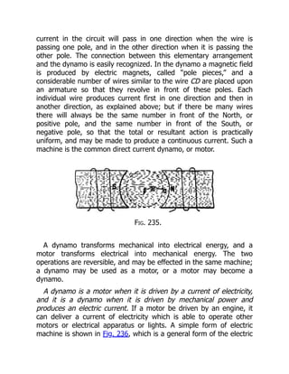
Fig. 235.
A dynamo transforms mechanical into electrical energy, and a
motor transforms electrical into mechanical energy. The two
operations are reversible, and may be effected in the same machine;
a dynamo may be used as a motor, or a motor may become a
dynamo.
A dynamo is a motor when it is driven by a current of electricity,
and it is a dynamo when it is driven by mechanical power and
produces an electric current. If a motor be driven by an engine, it
can deliver a current of electricity which is able to operate other
motors or electrical apparatus or lights. A simple form of electric
machine is shown in Fig. 236, which is a general form of the electric
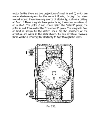
32.
motor. In thisthere are two projections of steel, H and G, which are
made electro-magnets by the current flowing through the wires
wound around them from any source of electricity, such as a battery
at I and J. These magnets have poles facing toward an armature, K,
on a shaft. The poles G and H are called the “salient” poles; the
poles M and P are called the “consequent” poles. The magnetic flow
or field is shown by the dotted lines. On the periphery of the
armature are wires in the slots shown. As this armature revolves,
there will be a tendency for electricity to flow through the wires.
Fig. 236.
33.
In order todistribute a current of electricity through these wires it
is necessary to make a complete circuit. As each of the wires in the
slots passes in front of a pole, a pressure or electro-motive force will
be generated, and its direction will depend upon whether the pole is
a North or a South pole, i.e., + or -.
Note.—In the above illustrations I and J represent the ordinary electric
battery; in electrical literature such marks always indicate a battery.
The pressure or electro-motive force generated in the wires
moving in front of the North, or positive field poles, will be in one
direction, while that of those in front of the South, or negative field
poles, will be in the opposite direction. Therefore, if two such wires
be connected together at one end of the armature, the free
terminals of the wires at the other end of the armature will have the
sum of the electro-motive forces generated in the two wires. The
wires so connected can be considered as a turn of a single wire
instead of two separate wires, and this turn may be connected in
series with other turns, so that the resulting electro-motive force is
the sum of that in all the turns and all the wires so connected. It is
customary to connect the coils of an armature so that the electro
motive force given is that obtained from half the coils in series. The
other half of the coils is connected in parallel with the first half, so
that the currents flowing in the two halves will unite to give a
current in the external circuit equal to twice the current in the two
armature circuits or paths.
It is evident that, as the armature revolves, wires which were in
front of the positive pole will pass in front of the negative, and that
in order to maintain the electro-motive force it will be necessary to
change the connections from the armature winding to the external
circuit in such a way that all the wires between the two points of
connection will have their electro-motive forces in the proper
direction. The connection to the armature must therefore be made
not at a definite point in the armature itself, but at a definite point
with reference to the field magnets, so that all the wires between
two points or contacts shall always sustain the same relation to the
field magnets.
34.
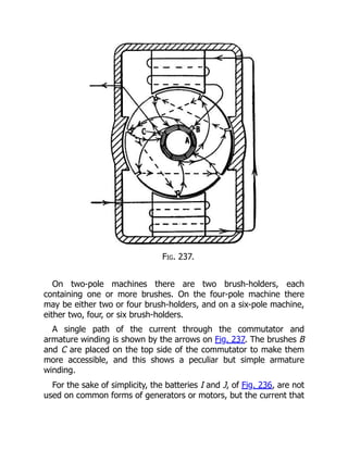
For this purposea device known as a “commutator” is provided.
The commutator is made up of a number of segments, as shown at
A, in Fig. 237, which are connected to the armature winding. On the
commutator, rest sliding contacts, or brushes, which bear on the
segments and are joined to an external circuit, making a continuous
path through which current may flow. As the commutator revolves,
the different segments come under the brushes, so that the relative
position of the armature wires between the brushes is dependent on
the position of the brushes. The armature wires which connect the
brushes are those sustaining the desired definite position to the field
magnets, so that the currents from the armature at all times flow
properly into the external circuit, although individual armature wires
carry currents first in one direction and then in the other direction,
depending on the character of the pole in front of which they may
be moving.
35.
Fig. 237.
On two-polemachines there are two brush-holders, each
containing one or more brushes. On the four-pole machine there
may be either two or four brush-holders, and on a six-pole machine,
either two, four, or six brush-holders.
A single path of the current through the commutator and
armature winding is shown by the arrows on Fig. 237. The brushes B
and C are placed on the top side of the commutator to make them
more accessible, and this shows a peculiar but simple armature
winding.
For the sake of simplicity, the batteries I and J, of Fig. 236, are not
used on common forms of generators or motors, but the current that
36.
flows from thearmature through the commutator is made to flow
through the electro-magnets either in whole or in part. If all of the
armature current flows around the electro-magnets or fields of the
machine, it is a “series” machine; if only a part of the current is used
in this way, it is a “shunt” machine; that is, some of the current is
“shunted” through the fields. Sometimes both the shunt and series
windings are used, and in that case the machine is called a
“compound wound” machine. Such a machine has a large wire
through which the main current passes, and a fine wire through
which the shunted current flows. Fig. 237 shows how the
commutator and the fields are connected, and how the current flows
from the wires in the armature through the commutator in a series
machine.
If the current delivered by a dynamo does not flow in the desired
direction, it can be reversed by shifting the wires in the binding
posts or by throwing a switch. If the motor does not revolve in the
desired direction, it can be made to do so by reversing the
connections to the armature or field-coils; so that, without knowing
which way a current of electricity is to be generated, any practical
man can make a motor revolve in a proper direction by simply
changing its connections.
It is natural that a machine which gives out electric energy when
driven by an external power, should, when electric energy is
delivered to it, reverse its action and give out mechanical power and
do work.
Perhaps the simplest way to explain the cause of the movement of
an electric motor, when supplied with a current, is to compare its
action to the well-known attraction of unlike poles or magnets and
the repulsion of like poles. Unlike poles are North and South; like
poles are two North or two South. In all motors a current through
the field causes a North or South pole to be maintained, and a
current through the armature and brushes causes an opposite
polarity. These constantly-maintained unlike poles attract each other
and pull the armature around on its axis.
37.
It has beenexplained that if a motor be driven by a belt an
electro-motive force is produced and the machine acts as a dynamo.
It is also a fact that an electro-motive force is produced whether the
power for driving the machine is received from a belt or from the
electric current,—that is, whether the machine be driven as a
dynamo or as a motor. In a dynamo, however, the current follows
the direction in which the electro-motive force is acting. In a motor,
the electro-motive force produced has a direction opposed to that of
the flow of current. This may be illustrated by the following
experiment.
Two similar machines are driven independently at 600 revolutions
and give an electro-motive force of 100 volts. Similar terminals of
the two machines are connected together; no current flows between
the machines, because the two pressures are the same and are in
opposite directions. If now the belt be thrown off from one machine,
its speed will begin to fall; this will lower its electro-motive force
below that of the other machine or dynamo, but will not change the
direction of the force. There will now be a difference of pressure in
favor of the machine which is driven, and it will deliver a current
through the other machine and run it as a motor. The speed of the
motor will continue to fall until the difference in pressure or electro-
motive force between the two machines is only sufficient to cause
the flow of enough current to keep the motor running against
whatever frictional resistance, and other resistance there may be.
The electro-motive force generated in the motor, which is against, or
counter to that of the current in the circuit, is called the “counter
electro-motive force.”
In order to determine how fast a motor will run without doing
work under any given pressure, it is not necessary to know anything
about the dynamo that furnishes the pressure. The pressure alone is
sufficient to determine the speed of the motor. For instance, if a
motor will give a pressure of 500 volts when running free at 100
revolutions, it will always run at about 100 revolutions when not
doing work on an electric circuit where the pressure is 500 volts.
38.
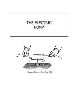
MAGNETIC NEEDLE.
The figureon page 242 shows a magnetic compass needle. This is
used to test the direction of an electric current flowing through a
wire or cable conductor. The plus sign, +, is the positive and the
minus, -, sign is the negative end or pole. A continuous current
always flows from the positive to the negative end or pole, hence
the north end or pole, N, is the positive end of the needle and the
south pole, S, is the south pole of the needle.
When one of these devices is held in close proximity to a
conductor of electricity it immediately assumes a parallel position to
the conductor and indicates the direction in which the current is
flowing. The long, upper arrow, as shown in the figure, tells the
direction of the flow. A small pocket compass may be used in place
of this device and is often carried in the pocket of electricians for the
purpose of indicating the direction of the current.
PRESSURE IS NECESSARY TO PRODUCE AN
ELECTRIC CURRENT.
It should be understood that an electric dynamo or battery does
not generate electricity, for if it were only the quantity of electricity
that is desired, there would be no use for machines, as the earth
may be regarded as a vast reservoir of electricity, of infinite quantity.
But electricity in quantity without pressure is useless, as in the case
of air or water, we can get no power without pressure, a flow of
current.
As much air or water must flow into the pump or blower at one
end, as flows out at the other. So it is with the dynamo; for proof
that the current is not generated in the machine, we can measure
the current flowing out through one wire, and in through the other—
it will be found to be precisely the same. As in mechanics a pressure
is necessary to produce a current of air, so in electrical phenomena
an electro-motive force is necessary to produce a current of
39.
Welcome to ourwebsite – the perfect destination for book lovers and
knowledge seekers. We believe that every book holds a new world,
offering opportunities for learning, discovery, and personal growth.
That’s why we are dedicated to bringing you a diverse collection of
books, ranging from classic literature and specialized publications to
self-development guides and children's books.
More than just a book-buying platform, we strive to be a bridge
connecting you with timeless cultural and intellectual values. With an
elegant, user-friendly interface and a smart search system, you can
quickly find the books that best suit your interests. Additionally,
our special promotions and home delivery services help you save time
and fully enjoy the joy of reading.
Join us on a journey of knowledge exploration, passion nurturing, and
personal growth every day!
ebookbell.com


![Electricity[1]](https://cdn.slidesharecdn.com/ss_thumbnails/electricity1-090926185857-phpapp01-thumbnail.jpg?width=640&height=640&fit=bounds)

![FORM 2 [CHAP 7] ELECTRICITY AND MAGNETISM](https://cdn.slidesharecdn.com/ss_thumbnails/f2cp7electricityandmagnetism-250714010423-54c050ae-thumbnail.jpg?width=640&height=640&fit=bounds)


