Downloaded 173 times


![Contents
Face-1/Face-2 Measurements . . . . . . . . . . . . . . . . 21
3 Getting Started . . . . . . . . . . . . . . . . . . . 23
Turning the Instrument On and Off . . . . . . . . . . . . . . 24
Turning on the instrument . . . . . . . . . . . . 24
Turning off the instrument . . . . . . . . . . . . 25
Selecting a Language . . . . . . . . . . . . . . . . . . . . 26
Changing Regional Configuration Pre-sets . . . . . . . . . . 27
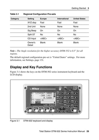
Display and Key Functions . . . . . . . . . . . . . . . . . 29
Status bar . . . . . . . . . . . . . . . . . . . 32
Adjusting lighting and sound levels . . . . . . . . . 34
[DSP] key . . . . . . . . . . . . . . . . . . . 35
[MODE] key . . . . . . . . . . . . . . . . . . . 37
[COD] key . . . . . . . . . . . . . . . . . . . 39
[HOT] key . . . . . . . . . . . . . . . . . . . 40
Bubble indicator . . . . . . . . . . . . . . . . 42
[LG] key. . . . . . . . . . . . . . . . . . . . 43
[USR] keys . . . . . . . . . . . . . . . . . . . 43
[DAT] key . . . . . . . . . . . . . . . . . . . 45
List Display . . . . . . . . . . . . . . . . . . . . . . . . 45
Inputting Data . . . . . . . . . . . . . . . . . . . . . . . 46
Entering a point name or number . . . . . . . . . 46
Entering a code. . . . . . . . . . . . . . . . . 50
Advanced feature: Searching for a code
by using the first character . . . . . . . . 51
Entering values in feet and inches . . . . . . . . . 52
Jobs . . . . . . . . . . . . . . . . . . . . . . . . . . . . 53
Creating a new job . . . . . . . . . . . . . . . 53
Measuring Distances . . . . . . . . . . . . . . . . . . . . 55
Sighting a prism reflector. . . . . . . . . . . . . 55
Measuring distances . . . . . . . . . . . . . . . 56
x iv Total Station DTM-502 Series Instruction Manual](https://image.slidesharecdn.com/nikon-dtm-502instruction-manual-english-110426153220-phpapp01/85/Nikon-DTN502-instruction-manual-english-14-320.jpg)
![Contents
Uploading a point name list or code list . . . . . . .158
1sec-Keys . . . . . . . . . . . . . . . . . . . . . . . . 159
[MSR] key settings . . . . . . . . . . . . . . . .159
[DSP] key settings . . . . . . . . . . . . . . . .160
[USR] key settings . . . . . . . . . . . . . . . .161
[S-O] key settings . . . . . . . . . . . . . . . .161
[DAT] key settings . . . . . . . . . . . . . . . .162
Calibration . . . . . . . . . . . . . . . . . . . . . . . 162
Time . . . . . . . . . . . . . . . . . . . . . . . . . . 162
6 Checking and Adjustment . . . . . . . . . . . . . 165
Checking and Adjusting the Plate Level . . . . . . . . . . 166
Checking and Adjusting the Circular Level . . . . . . . . . 166
Checking and Adjusting the Optical Plummet . . . . . . . . 167
Zero Point Errors of Vertical Scale and
Horizontal Angle Corrections . . . . . . . . . . . . 168
Checking . . . . . . . . . . . . . . . . . . .168
Adjusting . . . . . . . . . . . . . . . . . . .168
Checking the Instrument Constant . . . . . . . . . . . . . 172
7 Specifications. . . . . . . . . . . . . . . . . . . 175
Main Body . . . . . . . . . . . . . . . . . . . . . . . 176
Telescope . . . . . . . . . . . . . . . . . . .176
EDM . . . . . . . . . . . . . . . . . . . . .176
Dual-axis tilt sensor . . . . . . . . . . . . . . .177
Angle measurement . . . . . . . . . . . . . . .177
Precision . . . . . . . . . . . . . . . . . . .177
Measurement intervals . . . . . . . . . . . . .178
Lumi-guide . . . . . . . . . . . . . . . . . .178
Clamps/tangent screws . . . . . . . . . . . . .178
Tribrach . . . . . . . . . . . . . . . . . . .179
x v i ii Total Station DTM-502 Series Instruction Manual](https://image.slidesharecdn.com/nikon-dtm-502instruction-manual-english-110426153220-phpapp01/85/Nikon-DTN502-instruction-manual-english-18-320.jpg)
![Preparation 2
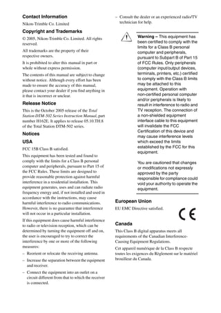
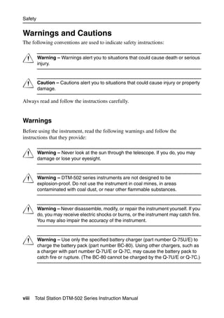
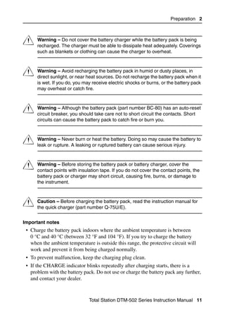
3. Press the DISCHARGE button on the battery charger.
The DISCHARGE indicator lights up, and the charger starts to discharge the
battery. When discharging is completed, the DISCHARGE indicator turns off.
Then the CHARGE indicator lights up, and charging starts automatically.
To stop discharging the battery pack, press the DISCHARGE button again.
Note – The battery pack can be recharged repeatedly. If you recharge the battery
pack while it still has enough power to operate the instrument, however, it will last
for a shorter period. This is called the memory effect. If you experience the memory
effect, discharge the battery pack as described above and then recharge it. This
returns the battery pack to its full capacity. We recommend that you discharge the
battery pack in this way at least once every ten charges.
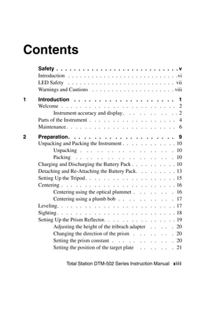
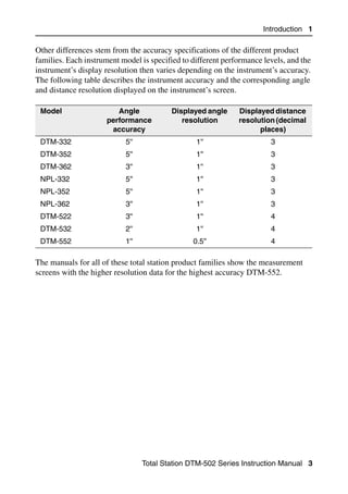
Detaching and Re-Attaching the Battery Pack 2.1
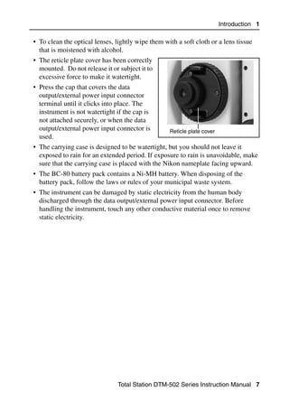
Detaching the BC-80 battery pack
C Caution – Avoid touching the contacts on the battery pack.
1. If the instrument is turned on, press [PWR] to turn it off.
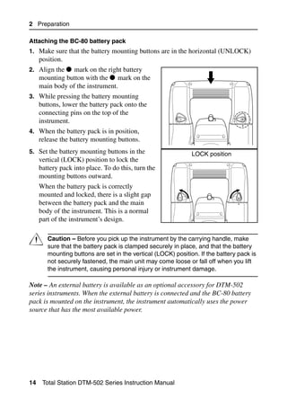
2. Set the battery mounting buttons in the
horizontal (UNLOCK) position. To do this,
turn each button inward.
3. While pressing both battery mounting
buttons, lift the battery pack off the main
body of the instrument.
Total Station DTM-502 Series Instruction Manual 13](https://image.slidesharecdn.com/nikon-dtm-502instruction-manual-english-110426153220-phpapp01/85/Nikon-DTN502-instruction-manual-english-33-320.jpg)
![Preparation 2
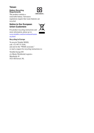
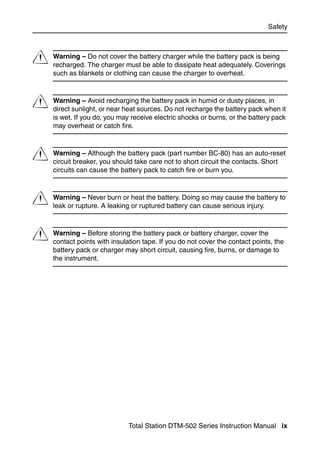
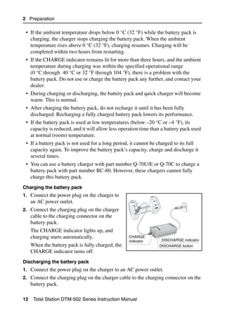
2. Set the prism constant. To do this, hold down
[MSR1] or [MSR2] for one second. For more
information, see Measurement settings,
page 57.
Note – The prism constant of a Nikon prism is
always 0, whether it is attached to a single
prism holder or a triple prism holder.
If your prism constant is not 0mm, then directly enter the prism constant value
in the Const field. For example, if your prism constant is 30mm, enter 30mm in the
Const field on the instrument.
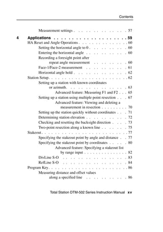
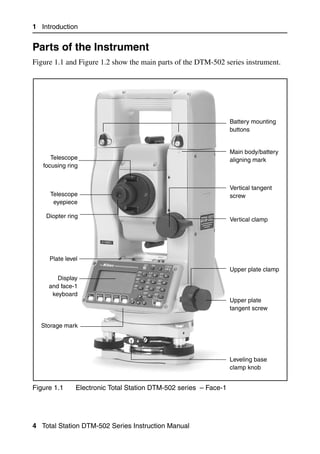
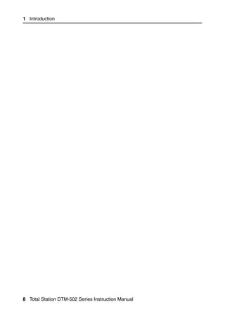
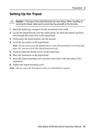
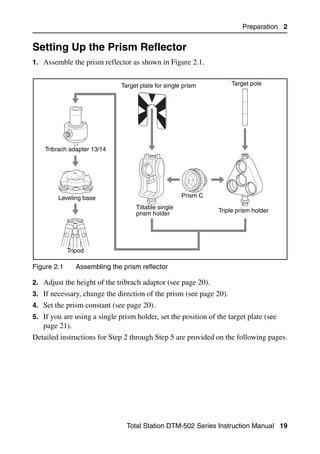
Setting the position of the target plate 20.1
If using a single prism, make sure that the target plate is aligned with the tribrach
adapter and the prism.
To set the position of the target plate:
1. Use the two set screws supplied to attach Center on axis
the target plate to the single prism holder.
2. Move the target plate within the screw
holes until the apex of the wedge pattern is
aligned with the vertical axis of the prism
and the tribrach adapter.
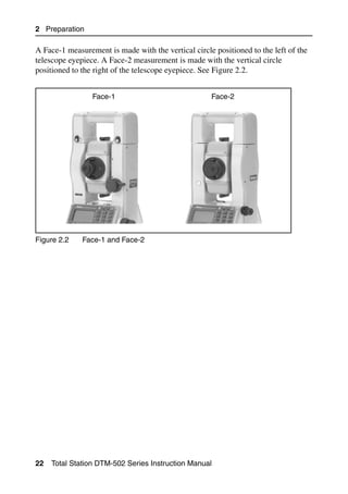
Face-1/Face-2 Measurements 2.1
You can take a measurement from either face of the instrument. To change the face,
rotate the instrument 180° on its base, and rotate the telescope 180° within the
standard.
By averaging the Face-1 and Face-2 measurement values, you can cancel out most
constant mechanical errors. Some errors, such as vertical axis error, cannot be
cancelled out by averaging Face-1 and Face-2 measurements.
C Caution – When rotating the telescope, take care not to catch your finger in
the gap between the instrument’s standard and the telescope.
Total Station DTM-502 Series Instruction Manual 21](https://image.slidesharecdn.com/nikon-dtm-502instruction-manual-english-110426153220-phpapp01/85/Nikon-DTN502-instruction-manual-english-41-320.jpg)
![3 Getting Started
Turning the Instrument On and Off 3.1
Turning on the instrument 31.1
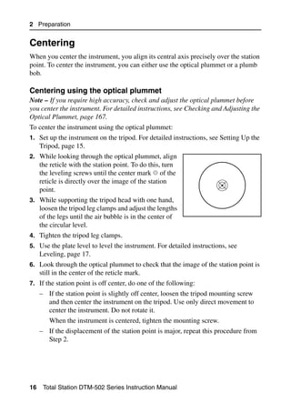
1. To turn on the instrument, press [PWR]. The
start-up screen appears. It shows the current
temperature, pressure, date, and time.
2. To change the temperature or pressure value,
use [^] or [v] to move the cursor to the field that
you want to change. Then press [ENT].
3. If you want to initialize the horizontal angle,
rotate the alidade.
4. Tilt the telescope until it passes the horizontal
position on Face-1.
If you have entered your name or your company’s
name in the Owner’s detail field, the text from this
field appears on the start-up screen. To set the
Owner’s detail field, go to MENU > Settings
> Other. For more information, see page 136.
Once you start to use an initialized HA, you must rotate the alidade to initialize the
HA every time you turn on the instrument. If you do this, you can maintain a fixed HA
orientation even if the instrument has moved while it is turned off.
If you tilt the telescope before you rotate the alidade, the horizontal angle is not
initialized, and the instrument uses the previous HA reading.
24 Total Station DTM-502 Series Instruction Manual](https://image.slidesharecdn.com/nikon-dtm-502instruction-manual-english-110426153220-phpapp01/85/Nikon-DTN502-instruction-manual-english-44-320.jpg)
![Getting Started 3
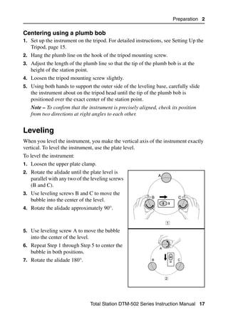
Turning off the instrument 30.1
To turn the instrument off, press [PWR] and [ENT].
Then do one of the following:
Press ... To ...
[ENT] again turn off the instrument
the Reset softkey reboot the program and re-start the instrument
the Sleep softkey put the instrument into power-saving mode
[ESC] cancel the power-off process and return to the
previous screen
If you press the Reset softkey, the software is rebooted and the Basic
Measurement Screen (BMS) appears without an open job.
Sleep mode
If you press the Sleep softkey in the Press [ENT]
→ OFF screen, or enable the Power Save setting
(see Power saving, page 134), the instrument goes
into sleep mode.
When the instrument is in sleep mode, it wakes up
if any of the following occurs:
• You press a key
• The instrument receives a remote control command
• You rotate the alidade
• You tilt the telescope
Total Station DTM-502 Series Instruction Manual 25](https://image.slidesharecdn.com/nikon-dtm-502instruction-manual-english-110426153220-phpapp01/85/Nikon-DTN502-instruction-manual-english-45-320.jpg)
![3 Getting Started
Selecting a Language 3.1
The Nikon total station supports one Language Pack at a time. The Language Pack
is a set of up to three different languages installed on the instrument from which the
user can select. Several Language Packs are available for the Nikon total stations.
• Language Pack #1: English, French, Spanish
• Language Pack #2: English, German, Italian
• Language Pack #3: English, Chinese, Russian
1. To select a different language, power on
the instrument and press [ESC] and [3] at the
Tilt Telescope screen.
The Select Language screen appears. Up to
three languages are available in the
installed Language Pack. The screen shows
which languages are currently available on
the instrument.
The current language selection is highlighted.
2. Press [^] or [v] to highlight the required
language and then press [ENT.]
3. The instrument reboots and displays the
start-up Tilt Telescope screen in the
selected language.
Language Pack #1 is the default Language Pack installed at the factory. Other
Language Packs can be installed at an authorized Nikon total station service
provider.
26 Total Station DTM-502 Series Instruction Manual](https://image.slidesharecdn.com/nikon-dtm-502instruction-manual-english-110426153220-phpapp01/85/Nikon-DTN502-instruction-manual-english-46-320.jpg)
![Getting Started 3
Changing Regional Configuration Pre-sets 3.1
To provide easier configuration for common regional settings, you can quickly
configure the Nikon total station to a pre-set combination of default regional
settings. The Regional Configuration screen appears only after the language
configuration is complete, the instrument has rebooted, and the telescope has been
tilted. To change the regional configuration pre-sets:
1. Follow the steps in Selecting a Language, page 26.
Once the instrument reboots and the
telescope is tilted, the Regional
Configuration screen appears.
2. Press [^] or [v] to highlight the required
regional settings and then press [ENT].
3. If you do not want to change the current
settings, press [ESC] and quit. The
instrument will continue to use the last configured settings that were configured.
The settings affected by the Regional Configuration screen are:
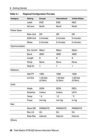
Table 3.1 Regional Configuration Pre-sets
Category Setting Europe International United States
Angle
VA zero Zenith Zenith Zenith
Resolution 1"(See note) 1"(See note) 1"(See note)
HA corr. On On On
HA Azimuth Azimuth Azimuth
Distance
Scale 1.000000 1.000000 1.000000
T-P corr. On On On
Sea Level Off Off Off
C&R corr. 0.132 0.132 0.132
Coordinates
Order ENZ ENZ NEZ
Total Station DTM-502 Series Instruction Manual 27](https://image.slidesharecdn.com/nikon-dtm-502instruction-manual-english-110426153220-phpapp01/85/Nikon-DTN502-instruction-manual-english-47-320.jpg)
![3 Getting Started
Table 3.2 summarizes the functions of the DTM-502 keys.
Table 3.2 Key functions
Key Function Details
Turns the instrument on or off. page 24
Illumination key. Turns the backlight on or off. page 34
Provides access to the 4-switch window if held down for
one second.
Displays the MENU screen. page 111
Changes the key input mode between alphanumeric page 37
and numeric if pressed when you are in a PT or CD
field.
Activates Qcode mode if pressed when you are In the
Basic Measurement Screen (BMS).
Records measured data, moves on to the next screen, page 99
or confirms and accepts the entered data in input mode.
You have the option to record the measurement as a CP
record instead of an SS record, if you hold this key down
for one second in the Basic Measurement Screen
(BMS).
The instrument outputs the current measurement data
(PT, HA, VA, and SD) on the COM port if you press this
key in the BMS or in a Stakeout observation screen.
(The Data Rec settings must be set to COM.)
Returns to the previous screen.
In numeric or alphanumeric mode, deletes input.
Starts distance measurement, using the measure mode page 55
settings for the [MSR1] key.
Displays measurement mode settings, if held down for
one second.
30 Total Station DTM-502 Series Instruction Manual](https://image.slidesharecdn.com/nikon-dtm-502instruction-manual-english-110426153220-phpapp01/85/Nikon-DTN502-instruction-manual-english-50-320.jpg)
![Getting Started 3
Table 3.2 Key functions (continued)
Key Function Details
Starts distance measurement, using the measure mode page 55
settings for the [MSR2] key.
Displays measurement mode settings, if held down for
one second.
Moves to the next available display screen. page 58
Changes the fields that appear on the DSP1, DSP2,
and DSP3 screens, if held down for one second.
Displays the Angle menu. page 60
Displays the Station Setup menu. page 62
In numeric mode, enters 7. In alphanumeric mode,
enters A, B, C, or 7.
Displays the Stakeout menu. page 77
Shows stakeout settings, if held down for one second.
In numeric mode, enters 8. In alphanumeric mode,
enters D, E, F, or 8.
Displays the Offset Point Measurement menu. page 101
In numeric mode, enters 9. In alphanumeric mode,
enters G, H, I, or 9.
Displays the Programs menu, which contains additional page 86
measuring programs.
In numeric mode, enters 4. In alphanumeric mode,
enters J, K, L, or 4.
Turns the Lumi-guide on or off. page 43
In numeric mode, enters 5. In alphanumeric mode,
enters M, N, O, or 5.
Displays RAW, XYZ, or STN data, depending on your page 45
setting.
In numeric mode, enters 6. In alphanumeric mode,
enters P, Q, R, or 6.
Total Station DTM-502 Series Instruction Manual 31](https://image.slidesharecdn.com/nikon-dtm-502instruction-manual-english-110426153220-phpapp01/85/Nikon-DTN502-instruction-manual-english-51-320.jpg)
![3 Getting Started
Table 3.2 Key functions (continued)
Key Function Details
Executes the function that is assigned to the [USR1] key. page 43
In numeric mode, enters 1. In alphanumeric mode,
enters S, T, U, or 1.
Executes the function that is assigned to the [USR2] key.
In numeric mode, enters 2. In alphanumeric mode,
enters V, W, X, or 2.
Opens a window where you can enter a code. The page 39
default code value is the last code entered.
In numeric mode, enters 3. In alphanumeric mode,
enters Y, Z, a space, or 3.
Displays the (HOT) menu, which includes Height of page 40
Target, Temp-Press, Target, Note recording, and Default
PT settings.
In numeric mode, enters – (minus). In alphanumeric
mode, enters . (period), – (minus), or + (plus).
Displays the Bubble indicator. page 42
In numeric mode, enters 0. In alphanumeric mode,
enters *, /, =, or 0.
Status bar 31.1
The status bar appears on the right side of
Status bar
every screen. It contains icons that indicate
the status of various system functions.
Signal indicator
The signal indicator shows the reflected light intensity:
Level 4 (maximum)
Level 3
32 Total Station DTM-502 Series Instruction Manual](https://image.slidesharecdn.com/nikon-dtm-502instruction-manual-english-110426153220-phpapp01/85/Nikon-DTN502-instruction-manual-english-52-320.jpg)
![Getting Started 3
Level 2
Level 1 (minimum)
If this icon is blinking, the signal is flickering.
If this icon is blinking rapidly, the signal is low.
If this icon is blinking slowly, there is no signal.
If there is no icon, analog power for EDM is off.
Input mode indicator
The Input mode indicator only appears when you are entering points or coordinates.
It shows the data input mode:
Input mode is numeric. Press a key on the number pad to enter the
number printed on the key.
Input mode is alphabetic. Press a key on the number pad to enter the first
letter printed beside the key. Press the key repeatedly to cycle through all
the letters assigned to that key.
For example, to enter the letter O in alphabetic mode, press [5] three times.
Lumi-guide indicator
The Lumi-guide indicator shows the status of the Lumi-guide tracking light:
Lumi-guide tracking light is on.
If there is no icon, the Lumi-guide tracking light is turned off.
Battery indicator
The battery indicator shows the battery voltage level:
Level 4 (Full)
Level 3
Level 2
Level 1
Battery low
Total Station DTM-502 Series Instruction Manual 33](https://image.slidesharecdn.com/nikon-dtm-502instruction-manual-english-110426153220-phpapp01/85/Nikon-DTN502-instruction-manual-english-53-320.jpg)
![3 Getting Started
If the battery level is critically low, the following
message appears:
Adjusting lighting and sound levels 31.2
LCD backlight
To turn the LCD backlight on or off, press the illumination key . To adjust the
backlight level, use the 4-switch window described below.
4-switch window
Use the 4-switch window to adjust lighting and
sound settings for the instrument.
To open the 4-switch window from any screen,
hold down the Illumination key for one second.
To cycle through the settings for a switch, press
the number beside that switch. For example, to
turn the backlight on or off, press [1].
Alternatively, to highlight the switch that you want to set, press [^] or [v]. Then press
[ENT] to cycle through the settings for that switch. For example, to adjust the reticle
light brightness, press [^] or [v] repeatedly until the reticle light switch is highlighted.
Then press [ENT] repeatedly until the required brightness level is reached.
Switch 1 (backlight)
LCD backlight is on.
LCD backlight is off.
Switch 2 (reticle light)
Reticle light is on the maximum setting.
Reticle light is on the medium setting.
Reticle light is on the minimum setting.
Reticle light is off.
34 Total Station DTM-502 Series Instruction Manual](https://image.slidesharecdn.com/nikon-dtm-502instruction-manual-english-110426153220-phpapp01/85/Nikon-DTN502-instruction-manual-english-54-320.jpg)
![Getting Started 3
Switch 3 (Lumi-guide)
Lumi-guide tracking light is on.
Lumi-guide tracking light is off.
Switch 4 (Sound)
Sound is on.
Sound is off.
Contrast adjustment window
When the 4-switch window is open, press [<] or [>]
to display the contrast adjustment window. Then
press [^] or [v] to change the contrast level. The
arrow indicates the current contrast level. To
return to the 4-switch window, press [<] or [>].
When you have finished changing display light
and sound settings, press [ESC] to close the
4-switch or contrast adjustment window.
[DSP] key 31.3
Use the key to change the current display screen or to change display settings.
Switching between display screens
When several display screens are available, the
DSP indicator appears at the top left of the screen,
and the screen indicator (for example, 1/4)
appears at the top right.
To move to the next available screen, press [DSP].
Total Station DTM-502 Series Instruction Manual 35](https://image.slidesharecdn.com/nikon-dtm-502instruction-manual-english-110426153220-phpapp01/85/Nikon-DTN502-instruction-manual-english-55-320.jpg)
![3 Getting Started
For example, if the DSP2 screen is currently
displayed, press [DSP] to move to the DSP3 screen.
The screen indicator changes from 2/4 to 3/4.
When the secondary distance unit is set, an
additional screen is available. It shows the HD,
VD, and SD values. For information on setting the
secondary distance unit, see page 136.
The smallest unit of display for distances
measured in feet-and-inches is 1/16 in. Smaller
units are impractical in the field. When the actual
value is greater than 99999'11''15/16, the “>”
symbol is shown. If the actual distance is less than -9999'11''15/16, the “ ” (solid
triangle) symbol is shown. This does not affect calculations. The precise value is
used internally in all cases.
Customizing items in the Basic Measurement Screen (BMS)
To customize the items that are displayed on the DSP1, DSP2, and DSP3 screens:
1. Hold down [DSP] for one second.
2. Use the arrow keys [^], [v], [<], and [>] to
highlight the item that you want to change.
3. Use the and softkeys to scroll through the
list of items that can be displayed for this item.
The items that you can choose from are HA,
AZ, HL, VA, V%, SD, VD, HD, Z, and (none).
4. To save your changes, press the Save softkey. Alternatively, highlight the last
item for DSP3 and press [ENT]. The DSP screens show the items you have
selected.
Except for the (none) item, you cannot display the same item on more than one line
of the same screen.
The items displayed in the DSP1, DSP2, DSP3, and DSP4 screens are also used in
the corresponding Stakeout screens (SO2, SO3, SO4, and SO5).
You can also customize the displayed items in Stakeout.
36 Total Station DTM-502 Series Instruction Manual](https://image.slidesharecdn.com/nikon-dtm-502instruction-manual-english-110426153220-phpapp01/85/Nikon-DTN502-instruction-manual-english-56-320.jpg)
![Getting Started 3
Header characters
The following header characters can be used in DSP screens:
A colon (:) indicates that tilt correction is applied
to the value.
A hash symbol (#) indicates that tilt correction is
off.
An underscore (_) under the tilt correction
character indicates that Sea Level Correction or
Scale factor is applied.
[MODE] key 30.1
Use the [MODE] key to change the keyboard mode for the current screen.
Changing input mode while entering points or codes
When the cursor is in a point (PT) or code (CD)
field, press [MODE] to change the input mode
between alphanumeric (A) and numeric (1).
The input mode indicator in the status bar changes
to show the current input mode.
When the cursor is in a height (HT) field, only numeric input mode is available.
Pressing [MODE] has no effect when the cursor is in a HT field.
Total Station DTM-502 Series Instruction Manual 37](https://image.slidesharecdn.com/nikon-dtm-502instruction-manual-english-110426153220-phpapp01/85/Nikon-DTN502-instruction-manual-english-57-320.jpg)
![3 Getting Started
Quick code measurement mode
1. To activate Quick code measurement mode,
press [MODE] in the BMS.
The PT field shows the default point name.
2. Press any numeric key ([0] through [9]) to start
measuring and recording points.
A list of the numeric keys and their assigned
feature codes appears on the right side of the
screen.
For example, when you press [6], the code
assigned to 6 is selected, and the instrument
starts a measurement.
3. If you have set the record mode to Confirm
(see Measurement settings, page 57), the
Record PT screen appears after each
measurement.
Do one of the following:
– To record the point, press [ENT].
– To return to the BMS, press [ESC].
To assign a new feature code to a numeric key, press [^] or [v] to highlight the code
that you want to change. Then press the Edit softkey.
You can use the DSP softkey to change the values shown in the measurement box,
in the same way as you use the [DSP] key in the Basic Measurement Screen (BMS).
4. To return to the BMS from the Qcode screen, press [MODE] or [ESC].
38 Total Station DTM-502 Series Instruction Manual](https://image.slidesharecdn.com/nikon-dtm-502instruction-manual-english-110426153220-phpapp01/85/Nikon-DTN502-instruction-manual-english-58-320.jpg)
![Getting Started 3
[COD] key 30.1
In the BMS, press [COD] to change the default feature code that will appear in the CD
field when you record a point.
Setting the default code
When you press [COD] in the BMS, a window for
entering the feature code appears.
You can use the List and Stack softkeys to
enter the code.
Qcode observations
To enter the Quick code observation routine, press
the Qcode softkey.
In this function, you can use the ten numeric keys
to both select a feature code and shoot a point.
To change the measurement mode for the Quick
code observation, press the Sett softkey.
In Quick code measurement, the Rec mode can only be set to Confirm or ALL.
Total Station DTM-502 Series Instruction Manual 39](https://image.slidesharecdn.com/nikon-dtm-502instruction-manual-english-110426153220-phpapp01/85/Nikon-DTN502-instruction-manual-english-59-320.jpg)
![3 Getting Started
[HOT] key 30.2
The HOT key menu is available on any
observation screen. To display the HOT key menu,
press [HOT].
Changing the height of the target
To change the height of the target, press [HOT] to
display the HOT menu. Then either press [1] or
select HT and press [ENT].
Enter the height of the target, or press the Stack
softkey to display the HT stack. The HT stack
stores the last 20 HT values entered.
Setting the temperature and pressure
To set the current temperature and pressure, press
[HOT] to display the HOT menu. Then either press
[2] or select Temp-Press and press [ENT]. Enter
the ambient temperature and pressure. The ppm
value is updated automatically.
Selecting the target set
A target set specifies settings for the target type,
the prism constant, and height of target. When you
change the selected target set, all three settings are
changed. You can use this function to quickly
switch between two types of target, such as a
reflector sheet and a prism. You can prepare up to
five target sets.
Press [HOT] to display the HOT menu. Then either press [3], or select Target and
press [ENT]. A list of the five target sets appears. To select a target set, either press the
corresponding numeric key ([1] through [5]), or use [^] or [v] to highlight the target set
in the list and press [ENT].
40 Total Station DTM-502 Series Instruction Manual](https://image.slidesharecdn.com/nikon-dtm-502instruction-manual-english-110426153220-phpapp01/85/Nikon-DTN502-instruction-manual-english-60-320.jpg)
![Getting Started 3
To change the settings defined in a target set, highlight the target set in the list.
Then press the Edit softkey.
Type Prism/Sheet
Const –999 to 999 mm
HT –9.9900 to 99.9900 m
HT can be left blank in the target set. If you leave it blank, the current HT value is
always applied to the measurement.
When a target set is selected, the Type and Const values are copied to both [MSR1]
and [MSR2] settings, and to the measurements in Qcode. If you have specified a
value for HT, this value is also copied to the current HT.
Entering a field note
To enter a field note, press [HOT] to display the
HOT menu. Then either press [4], or select Note
and press [ENT].
This function can be used at any time on any
observation screen.
Each note can be up to 50 characters.
The note is stored as a CO record in the raw data.
To display a list of previously used notes, press
the Stack softkey. The stack stores the last 20
notes.
Use [^] or [v] to highlight a note in the list. Then
press [ENT] to select the note.
Total Station DTM-502 Series Instruction Manual 41](https://image.slidesharecdn.com/nikon-dtm-502instruction-manual-english-110426153220-phpapp01/85/Nikon-DTN502-instruction-manual-english-61-320.jpg)
![3 Getting Started
Setting the default point name
To change the default point name, press [HOT] to
display the HOT menu. Then press [5], or select
Default PT and press [ENT].
This function is available from any observation
screen.
Modify the default point name for the next record.
Press [ENT] to confirm the new default point name.
The new point name is appears as the default PT
name on the input screen.
Bubble indicator 30.3
The bubble indicator is automatically displayed if the instrument goes out of level
while the compensators are turned on.
To display the bubble indicator in an observation screen, press .
To turn the leveling compensators on or off, press
[<] or [>]. When the leveling compensators are
turned off, the text OFF appears on the screen.
If the instrument is more than ±3'30" out of level,
the text OVER appears on the screen.
To return to the observation screen, press [ESC] or
[ENT] .
The current setting of leveling compensators is indicated by header characters (:, #,
:, and #) after field labels (such as HA, VA, SD, and HD) in observation screens. For
more information, see Header characters, page 37.
42 Total Station DTM-502 Series Instruction Manual](https://image.slidesharecdn.com/nikon-dtm-502instruction-manual-english-110426153220-phpapp01/85/Nikon-DTN502-instruction-manual-english-62-320.jpg)
![Getting Started 3
[LG] key 30.4
To turn the Lumi-guide tracking light on or off,
press [LG] in the Basic Measurement Screen
(BMS) or in any other measurement screen.
The Lumi-guide icon in the status bar shows
whether the Lumi-guide tracking light is turned on
or off. For more information, see Status bar,
page 32.
[USR] keys 30.5
If you use a function frequently in the field, you can assign it to the [USR1] or [USR2]
key. Whenever you press a [USR] key, the function that is assigned to that key is
activated directly.
The following functions can be assigned to the [USR] keys:
• Input HT
• BS Check
• Base XYZ
• Default PT
• Select Target
• Input Temp-Press
• Input Note
• The following menus, or a single function from one of these menus:
– Cogo
– O/S
– PRG
By default, Input HT is assigned to [USR1], and no function is assigned to [USR2].
Hold down the [USR] key for one second to display
the list of functions that can be assigned to the
key. The currently assigned function is indicated
by an asterisk (*) beside the function name.
To change the function that assigned to the key,
press [^] or [v] to highlight the function. Then press
[ENT].
Total Station DTM-502 Series Instruction Manual 43](https://image.slidesharecdn.com/nikon-dtm-502instruction-manual-english-110426153220-phpapp01/85/Nikon-DTN502-instruction-manual-english-63-320.jpg)
![3 Getting Started
If an item on the list has an arrow (->) beside it,
this item is a menu. If you highlight a menu item
and then press [ENT], a sub-menu appears.
The first item on the sub-menu ends with the text
[MENU]. If you select this item, the whole menu
is assigned to the [USR] key.
To assign a specific function from the sub-menu,
press [^] or [v] to highlight the function. Then press
[ENT].
Once you have assigned a function to a [USR] key,
it is called directly whenever you press that [USR]
key in the BMS.
To change the type of data that is assigned to the
[USR] keys in MENU > 1sec-Keys > [USR].
For more information, see [USR] key settings,
page 161.
44 Total Station DTM-502 Series Instruction Manual](https://image.slidesharecdn.com/nikon-dtm-502instruction-manual-english-110426153220-phpapp01/85/Nikon-DTN502-instruction-manual-english-64-320.jpg)
![Getting Started 3
[DAT] key 30.6
Use the [DAT] key to quickly access data in the current job from observation screens.
When you press [DAT] in the BMS or in
observation screens in functions such as Stakeout,
2Pt RefLine, and Arc RefLine, the assigned data
in the current job appears.
Hold down [DAT] for one second in the BMS or an
observation screen to display the Select Format
screen. Use this screen to change the type of data
that is assigned to [DAT]. Press [1] or select
DAT [MENU] to display the Data menu
whenever you press [DAT].
When you select an option from this screen, the
change is applied immediately, and the selected
data type appears.
Press [ESC] to return to the previous observation
screen.
To change the type of data that is assigned to
[DAT], go to MENU > 1sec-Keys > [DAT].
For more information, see [DAT] key settings,
page 162.
List Display 3.1
Available jobs or data appear in a list display when you do any of the following:
• view or edit data (MENU > Data)
• open the code list, point list, or Job Manager (MENU > Job)
• search for points or codes
Total Station DTM-502 Series Instruction Manual 45](https://image.slidesharecdn.com/nikon-dtm-502instruction-manual-english-110426153220-phpapp01/85/Nikon-DTN502-instruction-manual-english-65-320.jpg)
![3 Getting Started
In the list, the current cursor position is shown in
reverse video (it appears as white text on a black
background).
Press [^] or [v] move the cursor one line up or down.
If the Page Up icon appears, there are more
pages before the current page. Press [<] to move up
one page.
If the Page Down icon appears, there are more pages after the current page. Press
[>] to move down one page.
To select an item from the list, move the cursor onto the item and press [ENT].
Inputting Data 3.2
Entering a point name or number 32.1
You can use numeric or alphanumeric names up to 16 characters long to identify
points.
The default name for a new point is the last point name entered, with the last digit
incremented. For example, if the last point name was A100, the default name for the
next point is A101.
If the last character of the previous point name is alphabetic, the default point name
is the last point name.
When the cursor is in a PT (point) field, there are several ways to specify a point, or
input coordinates.
Entering an existing point
When you enter a known point name or number,
the coordinates of that point are displayed briefly.
A short beep sounds before the next screen
appears or the next field is selected.
46 Total Station DTM-502 Series Instruction Manual](https://image.slidesharecdn.com/nikon-dtm-502instruction-manual-english-110426153220-phpapp01/85/Nikon-DTN502-instruction-manual-english-66-320.jpg)
![Getting Started 3
To adjust the duration of the coordinate window
display, go to MENU > Settings >
Others. To leave the window open until you
press [ENT], set the XYZ disp field to +ENT. For
more information, see page 136.
Entering a new point
When you input a new point name or number, a
coordinate input screen appears. Enter the point’s
coordinates in NE, NEZ, or elevation-only (Z)
format.
Press [ENT] on the last line (the CD field) to store
the point in the current job.
Pressing [ENT] without a point name
To use a point without recording the coordinates,
press [ENT] in a PT field, without entering a point
name.
The input coordinates are used in the calculation.
They are not saved in the database.
Total Station DTM-502 Series Instruction Manual 47](https://image.slidesharecdn.com/nikon-dtm-502instruction-manual-english-110426153220-phpapp01/85/Nikon-DTN502-instruction-manual-english-67-320.jpg)
![3 Getting Started
Specifying a wildcard (*)
If you include an asterisk (*) when you enter a
point or code name, a list of points that match the
entered text appears.
Use [^] or [v] to move the cursor to the point that
you want to use. Then press [ENT].
If the Page Up or Page Down icons are
displayed, use [<] or [>] to page up or page down
the list.
When you select a point from the list, its
coordinates are displayed and a beep sounds.
Recording an instant measurement
You can also input a point by recording an instant
measurement. To do this, press the MSR softkey.
An observation screen appears.
Press [MSR1] or [MSR2] to start a measurement. To
change the height of the target, press the HT
softkey.
To go to the point recording screen when you have
finished the measurement, press [ENT].
Enter the point or code name. Press [ENT].
48 Total Station DTM-502 Series Instruction Manual](https://image.slidesharecdn.com/nikon-dtm-502instruction-manual-english-110426153220-phpapp01/85/Nikon-DTN502-instruction-manual-english-68-320.jpg)
![Getting Started 3
When you move the cursor to a field, the current
or default value appears in inverted text (this is
the default “Replace All” input mode).
Press [>] to change the input mode to Overwrite
mode and highlight the first character. Press [<] to
move the cursor the end of the string.
Entering a point from the stack
The point stack is a list of recently used points. To
display the stack, press the Stack softkey when
the cursor is in the PT field.
Use [^] or [v] to move the cursor to the point that
you want to use. Then press [ENT].
When you return to the point input screen, the
selected point name is entered in the PT field,
incremented by one. For example, if you selected
the A101 point, A102 appears in the PT field.
The stack shows the last 20 point names used, in chronological order from last used
to first used.
Entering a point from the point list
To display a list of existing points, press the List
softkey when the cursor is in the PT field.
Use [^] or [v] to move the cursor to the point that
you want to use. Then press [ENT].
Total Station DTM-502 Series Instruction Manual 49](https://image.slidesharecdn.com/nikon-dtm-502instruction-manual-english-110426153220-phpapp01/85/Nikon-DTN502-instruction-manual-english-69-320.jpg)
![3 Getting Started
When you return to the point input screen, the
selected point name is entered in the PT field. You
can add digits or alphabetic characters if required.
Entering a code 32.2
The CD (Code) field always defaults to the last code used. You can change the
selected code on the input point screen, or you can press [COD] in the BMS. For more
information, see [COD] key, page 39.
You can use numeric or alphanumeric names up to 16 characters long to identify
codes.
Entering a code directly
To enter a code directly, press [MODE] to change the
input mode to alphanumeric or numeric mode.
Then use the keypad to enter the code.
Entering a code from the stack
The code stack is a list of recently used codes. The
stack may contain up to 20 codes.
To display the stack, press the Stack softkey
when the cursor is in the CD field.
Use [^] or [v] to move the cursor to the code that
you want to use. Then press [ENT].
The selected code is copied to the CD field.
When the instrument is rebooted, the code stack is cleared.
50 Total Station DTM-502 Series Instruction Manual](https://image.slidesharecdn.com/nikon-dtm-502instruction-manual-english-110426153220-phpapp01/85/Nikon-DTN502-instruction-manual-english-70-320.jpg)
![Getting Started 3
Entering a code from the code list
To display a list of existing codes, press the List
softkey when the cursor is in the CD field.
To edit the code list, go to MENU > Data >
Code List. For more information, see Editing
an item in the point list or code list, page 152.
Use [^] or [v] to highlight the feature code that you
want to use. Then press [ENT].
A layer has an arrow at the end of the code label.
If you highlight a layer in the list and then press
[ENT], the codes and layers in that layer are
displayed.
When you return to the input screen, the selected
code is entered in the CD field.
Items are shown in alphabetic order.
You can also use the first character search to quickly find a code. For more
information, see Advanced feature: Searching for a code by using the first
character, page 51.
Advanced feature: Searching for a code by using the first
character
To find a code quickly when the code list appears,
use the first-character search.
For example, to see feature codes that begin with
T, use the keypad to enter the letter T. To do this,
press [1] twice.
After each press of the key, the input mode field
displays the selected letter. For example, if you
press [1], S appears. If you quickly press [1] again,
T appears. If you do not press the [1] key again, the
letter T is selected.
Total Station DTM-502 Series Instruction Manual 51](https://image.slidesharecdn.com/nikon-dtm-502instruction-manual-english-110426153220-phpapp01/85/Nikon-DTN502-instruction-manual-english-71-320.jpg)
![3 Getting Started
Once you have selected a letter, the cursor moves
to the feature code beginning with that letter.
If there is no code beginning with that letter, the
cursor moves to the next available letter.
Qcodes
Quick codes (Qcodes) let you shoot and record
many points with feature codes in the field. You
can register up to ten Quick codes. To register
Qcodes, press the Edit softkey. For more
information, see Quick code measurement mode,
page 38.
Press [MODE] to switch Qcodes on or off.
Press the Edit softkey to change the Qcode. You can edit the entire code, or just
the number at the end of the code.
You can still use [DSP] to change the background displays.
Entering values in feet and inches 32.3
When either US Survey Feet (US-Ft) or International Feet (I-Ft) is selected as the
distance unit, you can enter and display distances, HIs, HTs, and coordinate values
either in decimal feet, or in feet and inches For more information, see Unit,
page 135, and Others settings, page 136.
To enter values in feet and inches in an input screen, enter the elements, separated
by periods (.), in the following format:
<Feet> [.] <Inches> [.] <Numerator> [.] <Denominator> [ENT]
(0–11) (0–15) (0–99)
The default denominator is 16. If the denominator
is 16, you do not have to enter it, and it is not
displayed on the screen.
52 Total Station DTM-502 Series Instruction Manual](https://image.slidesharecdn.com/nikon-dtm-502instruction-manual-english-110426153220-phpapp01/85/Nikon-DTN502-instruction-manual-english-72-320.jpg)
![Getting Started 3
For example, if you enter
[2] [.] [0] [8] [.] [5] [.] [ENT], it appears as 2'08 5/ (2
feet, 8 and 5/16ths inches).
The following examples show how various values
are entered:
To enter ... Type ...
65' 5 3/8" [6] [5] [.] [5] [.] [3] [.] [8] [ENT]
65' [6] [5] [ENT]
65' 5" [6] [5] [.] [5] [ENT]
65' 5 3/8" [6] [5] [.] [5] [.] [6] [ENT]
5 3/8" [0] [.] [5] [.] [3] [.] [8] [ENT] or [0] [.] [5] [.] [6]
[ENT]
The numerator and denominator that you enter are automatically converted to the
closest value from the following list: 0, 1/8, 1/4, 3/8, 1/2, 5/8, 3/4, 7/8, 1/16, 3/16,
5/16, 7/16, 9/16, 11/16, 13/16, 15/16.
If the denominator is 16, it is not shown on the screen.
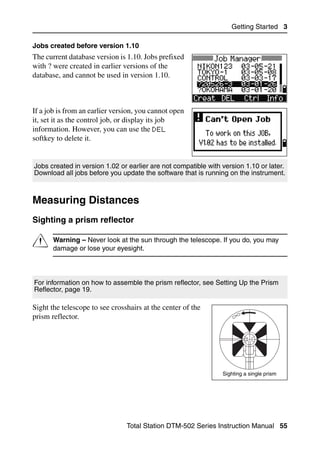
Jobs 3.3
To record data on the instrument, you must create or open a job.
C Caution – Before you use the instrument for the first time, check the job
settings.
Creating a new job 33.1
1. Press [MENU] to open the MENU screen.
2. Press [1] to open the Job Manager.
3. Press the Creat softkey to open the Create
Job screen.
Total Station DTM-502 Series Instruction Manual 53](https://image.slidesharecdn.com/nikon-dtm-502instruction-manual-english-110426153220-phpapp01/85/Nikon-DTN502-instruction-manual-english-73-320.jpg)
![3 Getting Started
4. Enter the job name.
5. Press the Sett softkey to check the job
settings. You cannot change a job’s settings
once you have created the job.
6. Press [ENT] in the last field of the Job Sett
screen to create the new job.
If either of the messages MAX 32JOBs or Data Full appears, delete at least one
existing job to free space. You cannot free space by deleting records in an existing
job.
Creating a control job
A control job, or common file, stores coordinate data that is used by several field
jobs. You can create a control job in the office.
1. Press [MENU] to open the MENU screen.
2. Press [1] or select Job to open the Job
Manager.
3. Move the cursor to the job that you want to use
as the control job.
4. Press the Ctrl softkey.
5. Press the Yes softkey.
For more information, see Creating a control job,
page 54.
When you enter a point name or number, the system searches in the current job
first. If the point is not found in the current job, the search is automatically extended
to the control job. If the point is found in the control job, the selected point is copied
to the current job as a UP record.
54 Total Station DTM-502 Series Instruction Manual](https://image.slidesharecdn.com/nikon-dtm-502instruction-manual-english-110426153220-phpapp01/85/Nikon-DTN502-instruction-manual-english-74-320.jpg)
![3 Getting Started
When a reflected lightwave is detected, the signal level is
indicated.
Sighting a tiltable single prism
Measuring distances 31.2
To take a distance measurement, press [MSR1] or
[MSR2] in the Basic Measurement Screen (BMS) or
in any observation screen.
While the instrument is taking a measurement, the
prism constant appears in a small font.
If the average count is set to 0, measurements are
taken continuously until you press [MSR1], [MSR2],
or [ESC]. Each time a measurement is taken, the
distance is updated.
If the average count is set to a value from 1 to 99,
the averaged distance appears after the last shot.
The field name SD changes to SDx to indicate the
averaged data.
56 Total Station DTM-502 Series Instruction Manual](https://image.slidesharecdn.com/nikon-dtm-502instruction-manual-english-110426153220-phpapp01/85/Nikon-DTN502-instruction-manual-english-76-320.jpg)
![Getting Started 3
If the signal level is insufficient to take a measurement, the signal icon flashes on
and off. For more information, see Status bar, page 32.
To change the height of target (HT), temperature,
or pressure, press [HOT]. For more information,
see [HOT] key, page 40.
Settings that relate to corrections
(T-P corr, Sea Level, C&R corr., and Map
projection) are included in the job settings. These
settings are job-specific. If you need to change
any of these settings, you must create a new job.
For more information, see Job settings, page 113,
and Settings, page 131.
Measurement settings 31.3
To view the measurement settings,hold down
[MSR1] or [MSR2] for one second.
Use [^] or [v] to move the cursor between the fields.
Use [<] or [>] to change the value in the selected
field.
Field Values
Target Prism
Sheet
Const (prism constant) –999 mm through 999 mm
Mode Prec0.1mm
Prec1mm
Normal1mm
Normal10mm
AVE (Average count) 0 (Continuous) through 99
Rec mode One of the following:
MSR only
Confirm
ALL
Total Station DTM-502 Series Instruction Manual 57](https://image.slidesharecdn.com/nikon-dtm-502instruction-manual-english-110426153220-phpapp01/85/Nikon-DTN502-instruction-manual-english-77-320.jpg)
![3 Getting Started
Target field
If the measurement is started with the Target field
set to Prism, there is a dash “–” in front of the
prism constant.
If the measurement is started with the Target field
set to Sheet, there is a right parenthesis “)” in
front of the prism constant.
The symbol then constantly runs from left to right over the prism constant in the
display.
The Target setting is used to apply better cyclic-error adjustment in distance
measurement. It efficiently eliminates multipath reflection.
Rec mode field
The Rec mode setting controls how the [MSR1] and [MSR2] keys operate in the BMS.
The MSR only setting is the default measurement mode. After a measurement, the
instrument stops in the BMS and waits for you to press [ENT] before recording the
point.
The Confirm setting displays the Record PT screen before data is recorded.
The ALL setting is a quick shooting and recording mode. The instrument
automatically records the point using the default PT/CD. The instrument then
returns to the BMS for the next measurement.
58 Total Station DTM-502 Series Instruction Manual](https://image.slidesharecdn.com/nikon-dtm-502instruction-manual-english-110426153220-phpapp01/85/Nikon-DTN502-instruction-manual-english-78-320.jpg)
![4 Applications
HA Reset and Angle Operations 4.1
To open the Angle menu, press [ANG] in the BMS.
To select a command from this menu, either press
the corresponding number key, or press [<] or [>] to
highlight the command and then press [ENT]
Setting the horizontal angle to 0 41.1
To reset the horizontal angle to 0, press [1] or select 0-Set in the Angle menu. The
display returns to the Basic Measurement Screen (BMS).
Entering the horizontal angle 41.2
To display the HA Input screen, press [2] or select
Input in the Angle menu. Use the numeric keys
to enter the horizontal angle. Then press [ENT].
To enter 123°45'50", type [1] [2] [3] [.] [4] [5] [5] [0].
The displayed value is rounded to the minimum angle increment.
Recording a foresight point after repeat angle measurement 41.3
1. To activate repeat angle measurement, press
[3] or select Rept. in the Angle menu.
HR=0 appears.
2. Sight the backsight and press [ENT].
3. Sight the foresight and press [ENT].
The horizontal angle is accumulated and the
value is held again.
4. To end repeat angle measurement, press [ESC].
60 Total Station DTM-502 Series Instruction Manual](https://image.slidesharecdn.com/nikon-dtm-502instruction-manual-english-110426153220-phpapp01/85/Nikon-DTN502-instruction-manual-english-80-320.jpg)
![Applications 4
5. When you have accumulated enough
horizontal angle between the backsight and the
foresight, press [MSR1] or [MSR2] to take a
measurement to the foresight.
The averaged horizontal angle appears. This
value is fixed until the process is finished or
cancelled.
HRx = HR∑ ÷ N
HA = BSAz + HRx (normalized)
HRx is not updated even if the instrument is
moved.
6. Press [ENT] to store the foresight as a CP
record. Check the PT, HT, and CD values.
Then press [ENT] to record.
In repeat angle measurement, the HA is replaced by HR∑. The number of repeat
angles appears at the top of the screen (for example, N= 5).
Horizontal angles can be measured up to 1999°59'59"5.
This function stores both raw and XYZ data as CP records, regardless of the Store
DB setting.
Face-1/Face-2 measurement 40.1
Use Face-1/Face-2 (F1/F2) measurements to obtain maximum accuracy for
measuring angles. Using F1/F2 measurements effectively cancels out mechanical
constant error, except for some special errors such as the vertical axis error. For
more information, see Face-1/Face-2 Measurements, page 21.
To take F1/F2 data without taking a distance
measurement, press [4] or select F1/F2 in the
Angle menu.
Total Station DTM-502 Series Instruction Manual 61](https://image.slidesharecdn.com/nikon-dtm-502instruction-manual-english-110426153220-phpapp01/85/Nikon-DTN502-instruction-manual-english-81-320.jpg)
![4 Applications
If you have already taken a distance measurement
to the target, you can initiate F1/F2 averaging by
flipping the telescope to the other face.
For the HA to be adjusted from a F1/F2
measurement, the Backsight must also have
been measured in F1/F2 during the station setup.
Horizontal angle hold 40.2
To hold the horizontal angle to the current value,
press [5] or select Hold in the Angle menu.
To set the horizontal angle to the displayed value,
press [ENT] or the Set softkey.
To cancel the process and return to the Basic
Measurement Screen (BMS), press [ESC] or the
Abrt softkey.
Station Setup 4.1
To open the Stn Setup menu, press [STN] in the
BMS.
To select a command from this menu, press the
corresponding number key. Alternatively, press [<]
or [>] to highlight the command and then press
[ENT]. Press [^] or [v] to move up or down one page.
The last function used is highlighted.
62 Total Station DTM-502 Series Instruction Manual](https://image.slidesharecdn.com/nikon-dtm-502instruction-manual-english-110426153220-phpapp01/85/Nikon-DTN502-instruction-manual-english-82-320.jpg)
![Applications 4
Setting up a station with known coordinates or azimuth 41.1
1. Press [1] or select Known in the Stn Setup
menu.
2. Enter a point name or number in the ST field.
– If the input point number or name is an
existing point, its coordinates are displayed
and the cursor moves to the HI (Height of
instrument) field.
– If the point is new, a coordinate input
screen appears. Enter the coordinates for
the point. Press [ENT] after each field. When
you press [ENT] in the CD field, the new
point is stored.
– If the specified point has a code, the code
appears in the CD field.
3. Enter the instrument height in the HI field and
then press [ENT].
The Backsight screen appears.
4. Select an input method for defining the
backsight point.
– To sight the backsight by entering
coordinates, see below.
– To sight the backsight by entering the
azimuth and angle, see page 66.
Total Station DTM-502 Series Instruction Manual 63](https://image.slidesharecdn.com/nikon-dtm-502instruction-manual-english-110426153220-phpapp01/85/Nikon-DTN502-instruction-manual-english-83-320.jpg)
![4 Applications
Sighting the backsight by entering coordinates
X
Z Backsight point
Xb
(Xb, Yb, Zb)
Instrument height
X0 Station point
(Xi, Yi, Zi)
Y
Y0 Yb
1. To enter coordinates for the backsight point
(BS), press [1] or select Coord in the
Backsight screen.
2. Enter the point name. If the point exists in the
job, its coordinates are shown.
3. If you intend to take a distance measurement
to the BS, enter the height of target in the HT
field.
4. Sight the BS on Face-1 (F1). Press [ENT] to
complete the setup.
– To record a full shot (with HA, VA, and SD
values) to the BS, press [MSR1] or [MSR2].
AZ Azimuth calculated by coordinates
– If you are measuring to a known
coordinate BS, press [DSP] to display a QA
screen. The QA screen shows the dHD and
dVD values, which indicate the difference
between the measured distance and the
distance calculated from the known
coordinates.
64 Total Station DTM-502 Series Instruction Manual](https://image.slidesharecdn.com/nikon-dtm-502instruction-manual-english-110426153220-phpapp01/85/Nikon-DTN502-instruction-manual-english-84-320.jpg)
![Applications 4
5. To record the station, press [ENT].
6. To finish the station setup after taking a
distance measurement, press [ENT]. ST and F1
records are stored to the current job.
Advanced feature: Measuring F1 and F2
To take an angle shot and proceed to the next
measurement on Face-2, press the F2 softkey.
To go directly to the Face-2 measurement after
taking a distance measurement to the BS on
Face-1, flip the telescope. The instrument
automatically detects F1/F2.
Press [ENT] on Face-2. The delta screen appears.
To record a CP record which stores the averaged
HA, VA, and SD from the F1/F2 data, press the
CP softkey. To record only the ST and F1/F2
records, without a CP record, press the OK
softkey.
Total Station DTM-502 Series Instruction Manual 65](https://image.slidesharecdn.com/nikon-dtm-502instruction-manual-english-110426153220-phpapp01/85/Nikon-DTN502-instruction-manual-english-85-320.jpg)
![4 Applications
Sighting the backsight by entering the azimuth angle
X
Z Backsight point
Instrument height Azimuth
X0 Station point
(Xi, Yi, Zi)
Y
Y0
1. To enter the azimuth angle to the backsight
point, press [2] or select Angle in the
Backsight screen.
2. If there is no point name for the BS, press [ENT]
on the BS field.
3. In the AZ field, enter the azimuth angle to the
BS point.
If you press [ENT] without entering a value in
the AZ field, the azimuth is automatically set
to 0°00'00".
4. Sight the BS point and press [ENT]. ST and F1
records are stored in the job.
You can also use the F2 softkey for F1/F2
measurements. See Advanced feature:
Measuring F1 and F2, page 65.
66 Total Station DTM-502 Series Instruction Manual](https://image.slidesharecdn.com/nikon-dtm-502instruction-manual-english-110426153220-phpapp01/85/Nikon-DTN502-instruction-manual-english-86-320.jpg)
![Applications 4
Setting up a station using multiple point resection 40.1
A resection sets up the station using angle/distance measurements to known points.
X
Z
Height 1
Height 2
X1 Known point 1
(X1, Y1, Z1)
X2
Known point 2
(X2, Y2, Z2)
Instrument height
X0 Station point (Xi, Yi, Zi)
Y
Y1 Y0 Y2
You can use a maximum of 10 points in a resection. Measurements can be distance
and angle, or angle only. Calculation starts automatically when enough
measurements are taken.
You can delete poor observations and recalculate if necessary. You can also select
the BS point.
If the angle between known point 1 and known point 2 (measured from the station
point) is extremely acute or extremely oblique, the resulting solution will be less
reliable geometrically. For geometric reliability, select known point locations (or
station point locations) that are widely spaced.
1. To start the resection, press [2] or select
Resection in the Stn Setup menu.
2. Enter the point name for the first observation
point (PT1).
Total Station DTM-502 Series Instruction Manual 67](https://image.slidesharecdn.com/nikon-dtm-502instruction-manual-english-110426153220-phpapp01/85/Nikon-DTN502-instruction-manual-english-87-320.jpg)
![4 Applications
3. Enter the target height and press [ENT].
4. Sight PT1 and press [MSR1] or [MSR2].
To use the F2 softkey for F1/F2
measurements, see Advanced feature:
Measuring F1 and F2, page 65.
5. To proceed to the next point, press [ENT].
6. Enter the second point (PT2) and its height of
target.
7. Measure to PT2 and press [ENT].
When the instrument has enough data, it
calculates the station (STN) coordinates.
– If more than the minimum required data is
available, a standard deviation screen
appears.
– To take measurements to strengthen
geometry of the resection, press the Add
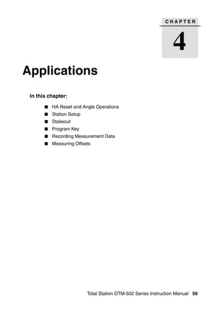
softkey. For information about the View
softkey, see Advanced feature: Viewing
and deleting a measurement in resection, page 70.
68 Total Station DTM-502 Series Instruction Manual](https://image.slidesharecdn.com/nikon-dtm-502instruction-manual-english-110426153220-phpapp01/85/Nikon-DTN502-instruction-manual-english-88-320.jpg)
![Applications 4
8. When the results are satisfactory, record the
station. To do this, press [ENT] or the REC
softkey.
9. Enter the height of instrument, if required.
Press [ENT]. The ST field defaults to the last
recorded PT + 1.
10. To change the station name, move to the ST
field and edit or replace the text.
If you have set Split ST to Yes, the ST field defaults to the last recorded ST
value + 1. For more information, see Others settings, page 136.
BS defaults to the first observed point.
11. To change the BS, press the Change softkey.
12. Select the BS point that you want to use and
press [ENT].
13. To finish the resection setup, move the cursor
to the BS field and press [ENT].
The minimum data required for a resection is either three angle shots, or one angle
shot and one distance shot. If you use a distance shot, the distance between the
target points must be greater than the measured distance.
Stn-Z is calculated from distance-measured data. If no distances are measured,
then Stn-Z is calculated using angle-only measurements to points with 3D
coordinates.
Total Station DTM-502 Series Instruction Manual 69](https://image.slidesharecdn.com/nikon-dtm-502instruction-manual-english-110426153220-phpapp01/85/Nikon-DTN502-instruction-manual-english-89-320.jpg)
![Applications 4
Setting up the station quickly without coordinates 40.1
The station point (ST) in this function defaults to a new point number. For the new
point, MP (0, 0, 0) is stored as the coordinates. When the ST is manually changed to
a known point name, the station is set up on the coordinates of the known point.
1. To enter Quick Station setup, press [3] or select
Quick in the Stn Setup menu.
ST Station point (defaults to the last
recorded PT + 1, or ST + 1, depending
on the Split ST setting)
HI Height of instrument
BS Backsight point (blank)
AZ Backsight azimuth (defaults to zero)
2. No default PT is assigned to the BS. Leave this
field blank, or enter a BS point name.
3. The backsight azimuth (AZ) defaults to zero,
but you can change this.
4. To complete the station setup, sight the BS and
press [ENT].
When you press [ENT] in the AZ field, both HA and AZ are reset to the value you
have entered.
Even if both ST and BS are known points, this function does not calculate the
backsight angle (AZ) automatically. To calculate the AZ between two known points
(ST and BS), use Station Setup > Known. For more information, see
Setting up a station with known coordinates or azimuth, page 63.
Total Station DTM-502 Series Instruction Manual 71](https://image.slidesharecdn.com/nikon-dtm-502instruction-manual-english-110426153220-phpapp01/85/Nikon-DTN502-instruction-manual-english-91-320.jpg)
![4 Applications
Determining station elevation 40.1
1. Press [4] or select Remote BM in the Stn
Setup menu.
2. Enter the BM point and press [ENT]. When the
point is found, it appears briefly. The cursor
then moves to the HT field.
3. Enter the HT and press [ENT].
4. Sight the BM point and press [MSR1] or [MSR2].
5. To take an F1/F2 measurement, press the F2
softkey or flip the telescope to Face-2 after a
distance measurement.
The updated station coordinates are displayed.
You can change the HI in this screen.
6. To record the updated STN, press [ENT].
When the HI is changed, the Z coordinate is updated before the station is recorded.
You must complete a station setup before you use the Remote Benchmark function.
72 Total Station DTM-502 Series Instruction Manual](https://image.slidesharecdn.com/nikon-dtm-502instruction-manual-english-110426153220-phpapp01/85/Nikon-DTN502-instruction-manual-english-92-320.jpg)
![Applications 4
Checking and resetting the backsight direction 40.1
You must complete a station setup before you use the BS check function.
This function always refers to the backsight point from the last ST record stored in
the current open job.
1. To enter the backsight (BS) check function,
press [5] or select BS Check in the Stn Setup
menu.
HA Current HA reading
BS The HA to the BS in the last station
setup. Enter station coordinates for
observations without recording data
2. Do one of the following:
– To reset the horizontal angle to the HA set
in the last station setup sight the BS and press the Reset softkey or press
[ENT].
– To cancel the process and return to the BMS, press the Abrt softkey or
press [ESC].
Total Station DTM-502 Series Instruction Manual 73](https://image.slidesharecdn.com/nikon-dtm-502instruction-manual-english-110426153220-phpapp01/85/Nikon-DTN502-instruction-manual-english-93-320.jpg)
![4 Applications
Base XYZ function:
Base XYZ does not store a ST record, so the BS Check cannot check the backsight
when you enter a station using Base XYZ.
To store raw data, use one of the other functions in the Stn Setup menu. This
function does not store an ST record in the job.
You can use this function without an open job. If there is an open job when you use
this function, a CO record is stored to indicate that the instrument’s base
coordinates have changed.
1. To enter the Base XYZ function, press [6] or
select Base XYZ in the Stn Setup menu.
The current instrument XYZ values are shown
as the default.
2. Enter the new instrument XYZ values and
press [ENT].
3. Do one of the following:
– To reset the horizontal angle, enter a value in the HA field and press [ENT].
– If you do not need to reset the HA, leave
the HA field blank and press [ENT].
The display returns to the BMS.
74 Total Station DTM-502 Series Instruction Manual](https://image.slidesharecdn.com/nikon-dtm-502instruction-manual-english-110426153220-phpapp01/85/Nikon-DTN502-instruction-manual-english-94-320.jpg)
![Applications 4
Two-point resection along a known line 40.1
1. To enter the Known Line function, press [7] or
select Known Line in the Stn Setup menu.
2. Enter a known point as P1.
If you enter a new point name, a coordinate
input screen appears.
Sight P1 and press [MSR1] or [MSR2] to take a
measurement. Press [ENT].
3. Choose how you want to define a known line:
– To define the line by entering P2
coordinates, press [1] or select By Coord.
– To define the line by entering the azimuth,
press [2] or select By Angle.
4. If you select By Angle, the azimuth input
screen appears. Enter the angle value and press
[ENT].
A measurement screen appears.
5. Sight P2 and press [MSR1] or [MSR2] to take a
measurement. Press [ENT].
Total Station DTM-502 Series Instruction Manual 75](https://image.slidesharecdn.com/nikon-dtm-502instruction-manual-english-110426153220-phpapp01/85/Nikon-DTN502-instruction-manual-english-95-320.jpg)
![4 Applications
After the measurement to P2 is completed, the
coordinates of the station are calculated.
6. To record the station, press [ENT] or the REC
softkey.
7. To check your measurement, press the DSP
softkey. If you defined the line by entering its
azimuth, HD and VD between P1 and P2 are
displayed.
If you defined the line by entering the P2
coordinates, the difference of HD (dHD) and
VD (dZ) between your measurement data and
input coordinate data are displayed.
8. Enter the station name, the height of
instrument (HI), and a feature code (CD) if
required. The station name defaults to the last
recorded PT + 1, or last recorded ST + 1,
depending on the Split ST setting.
9. Backsight (BS) defaults to the first point (P1).
To change it, highlight the BS field and then
press the Change softkey.
10. To finish the setup and record the station, press
[ENT] in the BS field.
Sample records
CO, Temperature:20C Pressure:1013hPa Prism:0 …
ST,9005, ,265, ,1.2350,150.40300,150.40300
F1,265,1.6040,79.0010,90.30150,89.35260,
F1,200,1.4590,50.2300,269.4035,93.50110,
CO, P1-P2 HD=122.0350 VD=0.5600
76 Total Station DTM-502 Series Instruction Manual](https://image.slidesharecdn.com/nikon-dtm-502instruction-manual-english-110426153220-phpapp01/85/Nikon-DTN502-instruction-manual-english-96-320.jpg)
![Applications 4
Stakeout 4.1
FiLL
OUT
R
CUT
L
IN
IN OUT
Height
of target
R
L
FILL
CUT
To display the Stakeout menu, press [S-O].
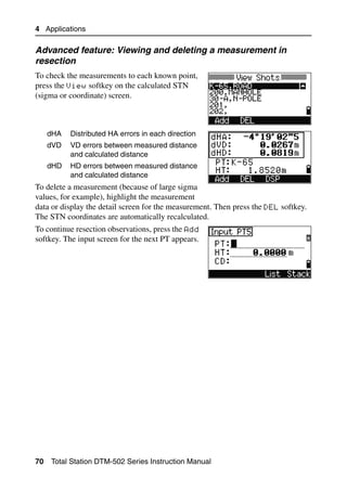
Specifying the stakeout point by angle and distance 41.1
1. To display the input screen for the distance and angle to the target, press [1] or
select HA-HD in the Stakeout menu.
2. Enter the values and press [ENT].
HD Horizontal distance from station point to
stakeout point
dVD Vertical distance from station point to
stakeout point
HA Horizontal angle to stakeout point
Total Station DTM-502 Series Instruction Manual 77](https://image.slidesharecdn.com/nikon-dtm-502instruction-manual-english-110426153220-phpapp01/85/Nikon-DTN502-instruction-manual-english-97-320.jpg)
![4 Applications
If you press [ENT] without entering HA, the current HA is used.
3. Rotate the instrument until the dHA is close to
0°00'00".
4. Sight the target and press [MSR1] or [MSR2].
When the measurement is completed, the
differences between the target position and the
stakeout point are displayed.
dHA Difference in horizontal angle to the
target point
R/L Right/Left (Lateral error)
IN/OUT In/Out (Longitudinal error)
CUT/FIL Cut/Fill
Once a measurement is taken, the Cut/Fill value and Z coordinate are updated as
the VA is changed.
If you press [HOT] in any observation screen, the
HOT key menu appears. You can use this menu at
any time to change HT and T-P.
78 Total Station DTM-502 Series Instruction Manual](https://image.slidesharecdn.com/nikon-dtm-502instruction-manual-english-110426153220-phpapp01/85/Nikon-DTN502-instruction-manual-english-98-320.jpg)
![Applications 4
Using [DSP] to switch between display screens
Press [DSP] to switch between the Stakeout display screens. The following screens
are available:
S-O1 S-O2 S-O3 S-O4
dHA← HA HA HL
R← VA VD V%
SD HD HD
OUT↑
CUT↑
S-O5 S-O6 S-O7 S-O8
X dX rSD HD
Y dY rVD VD
Z dZ rHD SD
The S-O8 screen is only available if the secondary distance unit is set. For more
information, see Others settings, page 136.
Every time you press [DSP], the next screen appears. If you press [DSP] in the last
screen (S-O7, or S-O8 if the secondary distance unit is set), the S-O1 screen
appears.
To customize the S-O2, S-O3, and S-O4 screens, hold down [DSP] for one second.
For more information, see Customizing items in the Basic Measurement Screen
(BMS), page 36.
To record the stakeout point, press [ENT]. PT
defaults to the last recorded PT+1.
Press [ENT] to record the point.
After recording the point, it returns to the
observation screen. You can continue observation,
or press [ESC] to input another angle and distance
for stakeout.
Total Station DTM-502 Series Instruction Manual 79](https://image.slidesharecdn.com/nikon-dtm-502instruction-manual-english-110426153220-phpapp01/85/Nikon-DTN502-instruction-manual-english-99-320.jpg)
![4 Applications
Specifying the stakeout point by coordinates 40.1
1. To start a stakeout by coordinates, press [2] or
select XYZ in the Stakeout menu.
2. Enter the point name that you want to stake
and press [ENT].
You can also specify the point by code or
radius from the instrument.
If several points are found, they are displayed
in a list. Use [^] or [v] to move up and down the
list. Use [<] or [>] to move up or down one page.
3. Highlight a point in the list and press [ENT].
The delta angle and the distance to the target
are shown.
4. Rotate the instrument until the dHA is close to
0°00'00". Press [MSR1] or [MSR2].
dHA Difference in horizontal angle to the
target point
HD Distance to the target point
5. Ask the rodman to adjust the target position.
When the target is on the intended position,
the displayed errors become 0.0000 m (or
0.0000 ft).
dHA Difference in horizontal angle to the
target point
R/L Right/Left (Lateral error)
IN/OUT In/Out (Longitudinal error)
CUT/FIL Cut/Fill
80 Total Station DTM-502 Series Instruction Manual](https://image.slidesharecdn.com/nikon-dtm-502instruction-manual-english-110426153220-phpapp01/85/Nikon-DTN502-instruction-manual-english-100-320.jpg)
![Applications 4
To switch between display screens, press [DSP]. This function works as in the angle-
distance stakeout, except that the screen counter (for example, S-O1/8) is not
displayed. For more information, see Using [DSP] to switch between display screens,
page 79.
During observation, you can use the flashing Lumi-guide to indicate distance.
To set the tolerance for the Lumi-guide flash speed, press [S-O] in any observation
screen. For more information, see Stakeout, page 134.
Once a measurement is taken, the Cut/Fill value and Z coordinate are updated as
the VA is changed.
6. To record the point, press [ENT]. PT defaults to
the specified PT + 1000.
Use the Add Constant field in MENU >
Settings > Stakeout to specify an
integer that is added to the point number being
staked to generate a new number for recording
the staked point. The default value is 1000. For
example, when you stake out PT3 with an Add
Constant of 1000, the default number for SO
record is 1003. For more information, see
Stakeout, page 134.
After recording the point, the display returns to
the observation screen. When you press [ESC], the
display returns to the PT/CD/R input screen. If
you entered the stakeout point using a single point
name, the PT defaults to the last PT + 1.
If you selected a point from the list, the display
returns to the list, unless all points have been
selected. Press [ESC] to return to the point input
screen.
Total Station DTM-502 Series Instruction Manual 81](https://image.slidesharecdn.com/nikon-dtm-502instruction-manual-english-110426153220-phpapp01/85/Nikon-DTN502-instruction-manual-english-101-320.jpg)
![4 Applications
Advanced feature: Specifying a stakeout list by range input
1. To input points by range, press the Fr/To
softkey in the PT field.
2. Enter the start point (Fr) and the end point
(To). The range between Fr and To must be
less than 1001 points.
If existing points are found between Fr and To,
a point list appears.
To highlight a point, press [^] or [v]. To go to the
stakeout observation screen, press [ENT].
If you have assigned a control job, and
additional points are found in the control job,
the Ctrl softkey appears under the list.
82 Total Station DTM-502 Series Instruction Manual](https://image.slidesharecdn.com/nikon-dtm-502instruction-manual-english-110426153220-phpapp01/85/Nikon-DTN502-instruction-manual-english-102-320.jpg)
![Applications 4
DivLine S-O 40.1
This function divides the line between the instrument and the first target by an input
span number. It then guides you to stake out the points, one by one.
1. Press [3] or select DivLine S-O in the
Stakeout menu.
2. Set up the baseline. To do this, sight the target
on the line (the end point) and press [MSR1] or
[MSR2].
3. Enter the total stake number in the Span total
field.
The observation screen for the first stake (from
the instrument) appears.
4. Sight the prism and press [MSR1] or [MSR2].
5. Use [^] or [v] to change the guide point. You can
calculate and guide up to double the number of
the stakes.
6. To record the point as an SO record, press
[ENT].
Total Station DTM-502 Series Instruction Manual 83](https://image.slidesharecdn.com/nikon-dtm-502instruction-manual-english-110426153220-phpapp01/85/Nikon-DTN502-instruction-manual-english-103-320.jpg)
![4 Applications
For example, if you measure to the end point at 100 m from the instrument and set
the span total to 2, the following four points are calculated and can be staked:
<1/2> <2/2> <3/2> <4/2>
HD 50 m 100 m 150 m 200 m
RefLine S-O 40.1
This function allows you to stake out a point based on the Sta, O/S, and dZ to a
specified line.
1. Press [4] or select
RefLine S-O in the Stakeout menu.
2. Enter the first point (P1) of the line.
If you press [ENT] without entering a PT name, you
can enter temporary coordinates which are not
recorded in the job.
Alternatively, press the MSR softkey to measure a
point.
84 Total Station DTM-502 Series Instruction Manual](https://image.slidesharecdn.com/nikon-dtm-502instruction-manual-english-110426153220-phpapp01/85/Nikon-DTN502-instruction-manual-english-104-320.jpg)
![Applications 4
3. Enter the second point (P2) of the line.
4. Enter offsets to the line.
Press [ENT] in a blank field to enter the value
0.0000.
Sta Distance from P1 along the line
O/S Distance perpendicular to the line
(+) Right side of the P1−P2 line
(-) Left side of the P1−P2 line
dZ Difference in height from the line
5. Rotate the instrument until the dHA is close to
0°00'00".
6. Sight the target and press [MSR1] or [MSR2].
When a distance measurement is taken, the
difference from the design point appears.
7. To record the point as an SO record, press
[ENT].
Using [DSP] to switch between display screens
You can use [DSP] to switch between display screens. This function works as in the
angle-distance stakeout. For more information, see Using [DSP] to switch between
display screens, page 79.
Total Station DTM-502 Series Instruction Manual 85](https://image.slidesharecdn.com/nikon-dtm-502instruction-manual-english-110426153220-phpapp01/85/Nikon-DTN502-instruction-manual-english-105-320.jpg)
![4 Applications
Program Key 4.1
To display the Programs menu, press [PRG].
Measuring distance and offset values along a specified line 41.1
1. Press [1] or select 2Pt RefLine in the
Programs menu.
2. Enter the first point for the reference line.
Alternatively (to enter the point by
measuring), press the MsrPT softkey.
Direct Measurement screen
Press the MsrPT softkey to display a direct
measurement screen.
Sight the target and press [MSR1] or [MSR2]. The
Record PT screen appears.
If you press [ESC] in the Record PT screen, the
measured point is used but not recorded in the
job.
3. Enter the second point for the reference line.
4. Enter an asterisk (*) in the PT field to perform
a wildcard search. A list of matching points
appears. Highlight a point in the list and then
press [ENT].
86 Total Station DTM-502 Series Instruction Manual](https://image.slidesharecdn.com/nikon-dtm-502instruction-manual-english-110426153220-phpapp01/85/Nikon-DTN502-instruction-manual-english-106-320.jpg)
![Applications 4
PT2 Prism
dZ PT2
Sta O/S
Prism PT1
PT1 Sta
Plain view Side view
5. Sight the prism or reflective sheet and press
[MSR1] or [MSR2].
Sta Horizontal distance from P1 to the
measure point along the P1-P2 line
O/S Horizontal offset from the P1-P2 line to the measured point
dZ Vertical offset from the P1-P2 line to the measured point
Using [DSP] to switch between display screens
Press [DSP] to switch between the Stakeout display screens. The following screens
are available:
REF1 REF2 REF3 REF4
Sta X HA HA
O/S Y VA VD
dZ Z SD HD
REF5
HD
VD
SD
The REF5 screen is only available if the secondary distance unit is set. For more
information, see Others settings, page 136.
Every time you press [DSP], the next screen appears. If you press [DSP] in the last
screen (REF4 or REF5), the REF1 screen appears.
Total Station DTM-502 Series Instruction Manual 87](https://image.slidesharecdn.com/nikon-dtm-502instruction-manual-english-110426153220-phpapp01/85/Nikon-DTN502-instruction-manual-english-107-320.jpg)
![4 Applications
To store the point and its offset distance
information, press [ENT].
Enter the point name and feature code.
You can also use this screen to change the HT
value.
Sample records
CO, 2pt-Ref Pt:16 & Pt:13 Az:311.2932
CO, Sta= -12.6876 Offset= 1.3721 dZ= 0.0971
SS,17,1.0000,6.9202,18.4700,80.3120,15:48:48,2REF-LINE
Measuring distance and offset values on the arc-curve 40.1
1. Press [2] or select Arc RefLine in the
Programs menu.
2. Enter the start of the curve point (P1) and the
azimuth of its tangent line (AZ1).
3. To enter P1 by direct measurement, press the
MSR softkey.
4. Choose a method to define the arc.
P2 can be any point on the tangent line that is
to exit the curve.
88 Total Station DTM-502 Series Instruction Manual](https://image.slidesharecdn.com/nikon-dtm-502instruction-manual-english-110426153220-phpapp01/85/Nikon-DTN502-instruction-manual-english-108-320.jpg)
![Applications 4
5. In the radius (Rad) field, enter a positive value
for a clockwise curve. Enter a negative value
for a counterclockwise curve.
When all factors have been entered, the instrument calculates the curve.
If the curve length (Len) is too large for a circle of
the given radius, it is shortened.
To ... Press ...
switch between display screens [DSP]
change HT [HOT]
record points [ENT]
Total Station DTM-502 Series Instruction Manual 89](https://image.slidesharecdn.com/nikon-dtm-502instruction-manual-english-110426153220-phpapp01/85/Nikon-DTN502-instruction-manual-english-109-320.jpg)
![4 Applications
Using [DSP] to switch between display screens
Press [DSP] to switch between the Stakeout display screens. The following screens
are available:
ARC1 ARC2 ARC3 ARC4
Sta X HA HA
O/S Y VA VD
dZ Z SD HD
ARC5
HD
VD
SD
The ARC5 screen is only available if the secondary distance unit is set. For more
information, see Others settings, page 136.
Every time you press [DSP], the next screen appears. If you press [DSP] in the last
screen (ARC4 or ARC5), the ARC1 screen appears.
To record the point, press [ENT] on any observation
screen. The arc is stored in comment records.
Sample records
CO,Arc P1:583 AZ1=0.0000 P2:102
CO, AZ2=311.2932 Radius=50.0000 Length=125.6637
CO, Sta= -12.6876 Offset= 1.3721 dZ= 0.0971
SS,17,1.0000,6.9202,18.4700,80.3120,15:48:48,2REF-LINE
90 Total Station DTM-502 Series Instruction Manual](https://image.slidesharecdn.com/nikon-dtm-502instruction-manual-english-110426153220-phpapp01/85/Nikon-DTN502-instruction-manual-english-110-320.jpg)
![4 Applications
Measuring between the current and the first point measured
1. To enter the RDM (Radial) function, press [3]
or select RDM(Radial) in the Programs
menu.
2. Sight the first point and press [MSR1] or [MSR2].
The distance from the station point to the first
point appears.
3. Sight the second point and press [MSR1] or
[MSR2]. The distances between the first and
second point are displayed.
rSD Slope distance between two points
rVD Vertical distance between two points
rHD Horizontal distance between two points
4. To change display screens, press [DSP].
rAZ Azimuth from first point to second point
rV% Percentage of grade (rVD/rHD) × 100%
rGD Vertical grade (rHD/rVD): 1
5. To record the distance and angle information
as a comment record, press [ENT] in the 1/2 or
2/2 observation screen.
Default point numbers are displayed. You can
change these point numbers. To record a note,
press [ENT] in the To field.
92 Total Station DTM-502 Series Instruction Manual](https://image.slidesharecdn.com/nikon-dtm-502instruction-manual-english-110426153220-phpapp01/85/Nikon-DTN502-instruction-manual-english-112-320.jpg)
![Applications 4
Data that you save in RDM functions is stored in RM records. For more information,
see RM records, page 140. When you download data in Nikon RAW format, they
are output as comment (CO) records.
Measuring between the current point and the immediately preceding point
1. To enter the RDM (Continuous) function,
press [4] or select RDM(Cont.)in the
Programs menu.
2. Follow the procedure as for a radial RDM
measurement. For more information, see
Measuring between the current and the first
point measured, page 92.
Difference between “1:Cont.” and “2:Radial”
P3 P3
P4
P4
P2
P2
P1
P1
1:Cont.
(The preceding two points are 2:Radial.
subject to calculation.) (Calculations are made with
reference to the first point.)
Total Station DTM-502 Series Instruction Manual 93](https://image.slidesharecdn.com/nikon-dtm-502instruction-manual-english-110426153220-phpapp01/85/Nikon-DTN502-instruction-manual-english-113-320.jpg)
![4 Applications
Measuring remote elevation 40.1
Arbitrary point A prism is required
only at the sighting
(target) point
Sighting point
Station point
1. To enter the Remote Elevation Measurement
function, press [5] or select REM in the
Programs menu.
2. Enter the height of target.
3. Sight the target point and press [MSR1] or
[MSR2].
4. Loosen the vertical clamp, and turn the
telescope to aim at an arbitrary point.
The difference in elevation (Vh) appears.
94 Total Station DTM-502 Series Instruction Manual](https://image.slidesharecdn.com/nikon-dtm-502instruction-manual-english-110426153220-phpapp01/85/Nikon-DTN502-instruction-manual-english-114-320.jpg)
![Applications 4
You can use an REM measurement to update the height of target. Take a
measurement to the prism, sight the bottom of the prism pole, and press [ENT].
Measuring distance and offset values on the vertical plane 40.1
Baseline
1. To enter the 2-Pt Reference Plane function,
press [6] or select
V-Plane in the Programs menu.
2. Enter two points to define the plane.
– To enter the point by direct measurement,
press the MSR softkey.
When you press the MSR softkey, a temporary
observation screen appears.
3. Press [MSR1] or [MSR2]. The Record PT screen
appears.
Total Station DTM-502 Series Instruction Manual 95](https://image.slidesharecdn.com/nikon-dtm-502instruction-manual-english-110426153220-phpapp01/85/Nikon-DTN502-instruction-manual-english-115-320.jpg)
![4 Applications
4. Enter a value in the PT and CD fields. Press
[ENT].
5. Enter the second point on the vertical plane.
Press [ENT].
Once the plane is defined, the calculated Sta and
dZ values are updated as you move the telescope.
No distance measurement is required.
Sta Horizontal distance from P1 to the
target point along the baseline
dZ Vertical distance from P1 to the target
point
Using [DSP] to switch between display screens
Press [DSP] to switch between the plane display screens. The following screens are
available:
PLN1 PLN2 PLN3
Sta X HA
dZ Y VA
Z
Every time you press [DSP], the next screen appears. If you press [DSP] in the last
screen (PLN3), the PLN1 screen appears.
To record the point, press [ENT] on any screen (V-
PLN1/3 to V-PLN3/3).
Enter PT and CD. Then press [ENT].
Sample records
CO,Vertical Ref Plane Pt1:516-A1 Pt2:530
CO,Sta=68.021 dz=17.459
SS,30123-A48,1.5480,16.4020,40.4720,89.0730,14:22:47,
96 Total Station DTM-502 Series Instruction Manual](https://image.slidesharecdn.com/nikon-dtm-502instruction-manual-english-110426153220-phpapp01/85/Nikon-DTN502-instruction-manual-english-116-320.jpg)
![Applications 4
Measuring distance and offset values on the slope 40.1
Target
b (X,Y,Z) P3
P2 (X3,Y3,Z3)
(X2,Y2,Z2)
a P1
(X1,Y1,Z1)
Stn
1. To enter the 3-Pt Reference Plane function,
press [7] or select
S-Plane in the Programs menu.
2. Enter three points to define the slope plane. To
enter the point by direct measurement, press
the MSR softkey.
If you press [ENT] in a blank field, an input
screen for temporary coordinates appears.
These coordinates will not be stored.
When you have entered the temporary
coordinates, <Keyed-in XYZ> appears
instead of the PT name.
Total Station DTM-502 Series Instruction Manual 97](https://image.slidesharecdn.com/nikon-dtm-502instruction-manual-english-110426153220-phpapp01/85/Nikon-DTN502-instruction-manual-english-117-320.jpg)
![4 Applications
If the plane is defined by two points (by
selecting 2Pt), the vertical plane is the
same as the plane used in the V-Pln
function, but the indicating factors are Sta
and dZ, not a and b. For more information,
see Measuring distance and offset values
on the vertical plane, page 95.
Once the plane is defined, the calculated a and
b values are updated as you move the
telescope. No distance measurement is
required.
a Distance between P1 and the point that
is perpendicular to the target point
along the P1-P2 line
b Length of the perpendicular line from the target point to the P1-P2 line
Using [DSP] to switch between display screens
Press [DSP] to switch between the plane display screens. The following screens are
available:
PLN1 PLN2 PLN3
a X HA
b Y VA
Z
Every time you press [DSP], the next screen appears. If you press [DSP] in the last
screen (PLN3), the PLN1 screen appears.
To record the point, press [ENT] on any screen
(S-PLN1/3 to S-PLN3/3).
Enter PT and CD. Then press [ENT].
Sample records
CO,3ptPlane P1:1062 P2:2902 P3:1547
CO,a=31.497 b=14.239
SS,30123-A49,1.6110,0.0000,234.3210,86.0955,16:07:18,
98 Total Station DTM-502 Series Instruction Manual](https://image.slidesharecdn.com/nikon-dtm-502instruction-manual-english-110426153220-phpapp01/85/Nikon-DTN502-instruction-manual-english-118-320.jpg)
![Applications 4
Recording Measurement Data 4.1
Recording data from any observation screen 41.1
To record points on observation screens, press
[ENT].
PT defaults to the last recorded PT + 1.
You can enter the PT name from the point list or
the point stack. For more information, see
Entering a point from the point list, page 49, and
Entering a point from the stack, page 49.
You can also use the code list or the code stack. For more information, see Entering
a code from the code list, page 51, and Entering a code from the stack, page 50.
To record the point, press [ENT] on the last field.
When recording sideshots, stakeout records and
control shots from the Rept function, you can
choose to store raw data only, XYZ data only, or
both. For more information, see Recording,
page 136.
If HA or VA is moved after you take a measurement but before you press [ENT], the
angle recorded is the angle shown when [ENT] is pressed.
In an angle-only record, SD is always recorded as 0.0000.
If the point name that you want to record already
exists in the job, an error message appears.
Depending on the type of existing record, you can
overwrite the old record with the new data. For
more information, see Recording Data, page 207.
Hold down [ENT] for one second to record the
measurement as a CP record.
Total Station DTM-502 Series Instruction Manual 99](https://image.slidesharecdn.com/nikon-dtm-502instruction-manual-english-110426153220-phpapp01/85/Nikon-DTN502-instruction-manual-english-119-320.jpg)
![4 Applications
Outputting data to the COM port 41.2
If you press [ENT] while the [COM] icon appears in
an observation screen, a line of data is output to
the COM port.
Note – If [COM] appears, data is not stored to the job when you press [ENT].
The format of the output data is defined by the
setting of the Ext.Comm field in MENU >
Settings > Comm. For more information, see
Communications, page 134.
To output data on the COM port when you press
[ENT], set the Data Rec field in MENU >
Settings > Rec to COM. For more
information, see Recording, page 136.
Sample output records through COM port
When the Ext.Comm field is set to NIKON:
TR PN: PT8 SD:000066626 HA:003856010 VA:008048500 HT:0000061757
(TR PN: point name SD HA VA HT; when ACK is returned, PN is incremented.)
When the Ext.Comm field is set to SET:
0006662 0804806 0394324 97
(SD VA HA Chk-SUM)
100 Total Station DTM-502 Series Instruction Manual](https://image.slidesharecdn.com/nikon-dtm-502instruction-manual-english-110426153220-phpapp01/85/Nikon-DTN502-instruction-manual-english-120-320.jpg)
![Applications 4
Measuring Offsets 4.2
Measuring taped offsets 42.1
1. To enter the taped offset function, press [1] or
select Tape in the Offset menu.
If you have not taken a distance measurement
before entering this function, a temporary
measurement screen appears.
2. Sight the target and press [MSR1] or [MSR2].
3. Enter offset distances from the measured
point. Use [^] or [v] to move to the appropriate
offset field.
Left (-) Up (+)
Out (+)
Down (-)
In (-)
Right (+)
Total Station DTM-502 Series Instruction Manual 101](https://image.slidesharecdn.com/nikon-dtm-502instruction-manual-english-110426153220-phpapp01/85/Nikon-DTN502-instruction-manual-english-121-320.jpg)
![4 Applications
You can enter any combination of taped offset
distances to specify the point.
4. To go to the recording PT screen, press [ENT] in
the last field.
The calculated coordinates are shown.
5. Enter a PT (and CD) value.
6. Press [ENT] to record the point.
Raw data is also recalculated, based on the
taped offset value.
Measuring angle offsets 40.1
1. To enter the angle offset function, press [2] or
select Angle in the Offset menu.
If you have not taken a distance measurement
before entering this function, a temporary
measurement screen appears.
2. Sight the target and press [MSR1] or [MSR2].
3. To take the angle offset, rotate the alidade and
telescope. The measured distance (HD)
remains unchanged.
4. To record the offset point, press [ENT] or the OK
softkey.
The XYZ data is also recalculated, based on
the new angle.
You can record an angle offset in the Basic Measurement Screen (BMS). After
taking a distance measurement, rotate the alidade and/or telescope. Then press
[ENT] to record the measured distance with the updated angle value. If you use this
method, the dimension of the angle offset is not stored as a CO record. To store the
CO record, use the O/S function.
102 Total Station DTM-502 Series Instruction Manual](https://image.slidesharecdn.com/nikon-dtm-502instruction-manual-english-110426153220-phpapp01/85/Nikon-DTN502-instruction-manual-english-122-320.jpg)
![Applications 4
Two-prism pole 40.1
1. To enter the two-prism pole function, press [3]
or select 2Prism Pole in the Offset menu.
2. Sight the first prism and press [MSR1] or [MSR2].
3. Sight the second prism and press [MSR1] or
[MSR2].
4. Enter the distance between the second prism
and the target point. Alternatively, if you do
not need QA information, you can leave the
distance between the first and the second
prism blank.
5. If you do enter a P1-P2 distance, the QA
screen appears. Compare the entered value and
the measured distance to check the accuracy of
the observation.
6. To record the point, press [ENT] or the OK
softkey.
Sample records
SS,14,0.0000,38.9200,271.0350,89.2630,11:04:15,DITCH
CO,2Prism O/S: P1-P2= 0.5090( 0.5060) P2-Tgt= 0.5020
In this sample data, 0.5090 is the measured value. 0.5060 is the entered value.
Total Station DTM-502 Series Instruction Manual 103](https://image.slidesharecdn.com/nikon-dtm-502instruction-manual-english-110426153220-phpapp01/85/Nikon-DTN502-instruction-manual-english-123-320.jpg)
![4 Applications
Extending a line by horizontal angle offset 40.1
1. To enter the line extension (by HA) function,
press [4] or select +Line by HA in the Offset
menu.
2. Sight the first prism (or target) and press [MSR1]
or [MSR2].
The display moves to the next screen.
3. Sight the second prism (or target) and press
[MSR1] or [MSR2].
4. Sight the alternative place on the same vertical
line as the required target point.
5. To calculate the coordinates and the raw data of the target point, press [ENT].
104 Total Station DTM-502 Series Instruction Manual](https://image.slidesharecdn.com/nikon-dtm-502instruction-manual-english-110426153220-phpapp01/85/Nikon-DTN502-instruction-manual-english-124-320.jpg)
![Applications 4
6. To record the point, enter a PT (and CD) value
and press [ENT]. The height of target is fixed to
0.0000 for the offset point.
Sample records
SS, 40, 0.0000, 48.3304, 169.20370, 82.02470, 10:52:37
CO, PT1, 0.0000, 48.3020,169.19165, 83.58565
CO, PT2, 0.0000, 48.3155,168.54250, 85.42440
CO, O/S MSR:40 0.0000 0.0000 169.20370 87.02340
The calculated point (TGT) is stored as a SS record.
Measurements to the first and second target (P1 and P2) are stored as comment
records (PT1 and PT2). The last record records the angle measurement to the ALT
(vertically offset point from the actual target point).
Total Station DTM-502 Series Instruction Manual 105](https://image.slidesharecdn.com/nikon-dtm-502instruction-manual-english-110426153220-phpapp01/85/Nikon-DTN502-instruction-manual-english-125-320.jpg)
![4 Applications
Entering a horizontal distance after an angle-only shot 40.1
This function is useful when the instrument is very close to the point and it is
difficult to take a measurement using the EDM.
1. To enter the Input HD function, press [5] or
select Input HD in the Offset menu.
2. Turn the telescope in the direction of the point
that you want to store.
3. Enter the HD. Usually this is the taped
distance from the instrument point.
4. Enter a PT (and CD) value and press [ENT].
The target point is calculated and recorded as
an SS record.
Sample records
SS,158,0.0000,77.0518,62.08380,108.06510,11:51:48,
CO, Input HD:76.1243
106 Total Station DTM-502 Series Instruction Manual](https://image.slidesharecdn.com/nikon-dtm-502instruction-manual-english-110426153220-phpapp01/85/Nikon-DTN502-instruction-manual-english-126-320.jpg)
![Applications 4
Calculating a corner point 40.1
1. To enter the corner point function, press [6] or
select Corner in the Offset menu.
2. Take a distance measurement to the first prism
(or target) on the wall. Press [MSR1] or [MSR2].
3. Sight a second point on the same wall with the
first point measurement. Press [MSR1] or [MSR2].
4. Sight the first point on the second wall. Press
[MSR1] or [MSR2].
5. If the two walls are at right angles, press the
Calc softkey to calculate the corner point by
three points.
6. If you take a measurement to a fourth point,
the corner point can be calculated as the
intersection of two walls (P1-P2 and P3-P4).
The default elevation is given by P4.
Total Station DTM-502 Series Instruction Manual 107](https://image.slidesharecdn.com/nikon-dtm-502instruction-manual-english-110426153220-phpapp01/85/Nikon-DTN502-instruction-manual-english-127-320.jpg)
![4 Applications
7. Enter a PT (and CD) value. The height of
target (HT) defaults to the value used in the
last measurement.
8. To record the corner point, press [ENT].
Sample records
SS, 58, 0.0000, 48.3304, 169.19165, 82.02470, 10:52:37, FLOOR2
CO, PT1, 1.0080, 48.3020,169.19165, 83.58565
CO, PT2, 1.0080, 48.3155,128.54250, 85.42440
CO, O/S MSR:40 0.0000 0.0000 169.20370 87.02340
The calculated corner point is stored as an SS record.
The next three or four comment records are measured points. For example:
CO, Point name (fixed to PT1, PT2 etc.), HT, SD, HA, VA.
Measuring circle offsets 40.1
1. To enter the circle center calculation function,
press [7] or select Circle in the Offset menu.
If you have not taken a measurement to the
circle before entering this function, a
temporary measurement screen appears.
2. Sight any point on the surface of the circle and
press [MSR1] or [MSR2].
If you use a prism attached to the surface of the circle for the distance
measurement, press the +SD softkey to eliminate the offset error (from the attached
point to the measured surface of the prism) before you press [ENT].
108 Total Station DTM-502 Series Instruction Manual](https://image.slidesharecdn.com/nikon-dtm-502instruction-manual-english-110426153220-phpapp01/85/Nikon-DTN502-instruction-manual-english-128-320.jpg)
![Applications 4
3. Sight one edge of the circle and press [ENT].
If you have taken a distance measurement to the center of the circle, press the
Calc softkey to calculate the offset using one edge angle observation.
4. Sight the other edge of the circle and press
[ENT].
The instrument calculates and records the
center of the circle.
It also calculates the coordinates of the center
point and the radius of the circle.
5. To record the point, press [ENT] or the OK
softkey.
Sample records
SS,71,1.5000,37.0518,32.08380,81.06510,11:51:48,
CO, PT1, 0.0000, 0.0000,47.05350, 83.58560
CO, PT2, 0.0000, 0.0000, 29.53010, 83.58560
CO,O/S MSR:71 1.5555 36.5418 38.28360 81.06510
CO,Radius of circle 0.356
CO,Input +SD:0.0020
The calculated point (center of the circle) is stored as an SS record.
The following one or two comment records are angle-measured points. For
example:
CO, Point name (fixed to PT1/ PT2), HT(0.0000), SD(0.0000), HA, VA.
If you press the +SD softkey before you sight Edge1, the input value is recorded at
the end.
Total Station DTM-502 Series Instruction Manual 109](https://image.slidesharecdn.com/nikon-dtm-502instruction-manual-english-110426153220-phpapp01/85/Nikon-DTN502-instruction-manual-english-129-320.jpg)
![4 Applications
Extending the slope distance 40.1
1. To enter the function for extending the slope
distance, press [8] or select Input dSD in the
Offset menu.
If you have not taken a distance measurement
before entering this function, a temporary
measurement screen appears.
2. Enter the slope distance that you need to add
or subtract. You can enter any value from
–99.990 through +99.990 m (–328.000
through +328.000 ft).
3. To record the point, press [ENT].
Sample records
SS,83,1.5000,77.0518,62.08380,81.06510,11:51:48,
CO,O/S MSR:83 1.5555 76.5518 62.08380 81.06510
110 Total Station DTM-502 Series Instruction Manual](https://image.slidesharecdn.com/nikon-dtm-502instruction-manual-english-110426153220-phpapp01/85/Nikon-DTN502-instruction-manual-english-130-320.jpg)
![5 Menu Key
Introduction 5.1
Use the MENU screen to access important
functions and settings.
To display the MENU screen, press the [MENU] key.
Job Manager 5.2
Use the job manager to open, create, delete, and
manage jobs. To open the Job Manager, press [1] or
select Job on the MENU screen.
If there are jobs stored on the instrument, the job
list appears, showing all the stored jobs. The
newest job appears at the top of the list.
If there are no jobs stored, the Create Job screen appears. See Creating a new job,
page 113.
Opening an existing job 52.1
The job list shows all the jobs stored on the
instrument, in descending date order.
The following symbols may be used to provide
extra information about jobs:
Symbol Meaning
* Current job.
@ Control job.
! Some of the job settings are different from the current job.
? Job was created in an older DB. Older files cannot be opened in
version 1.10 or later of the software.
Press [^] or [v] to move up or down the job list. Press [ENT] to open the highlighted job.
When you open a job, all job settings are automatically changed to match those used
in the open job.
112 Total Station DTM-502 Series Instruction Manual](https://image.slidesharecdn.com/nikon-dtm-502instruction-manual-english-110426153220-phpapp01/85/Nikon-DTN502-instruction-manual-english-132-320.jpg)
![Menu Key 5
Creating a new job 52.2
1. Press the Creat softkey in the job list.
2. Enter a job name of up to eight characters.
Press [ENT].
3. Do one of the following:
– To check the job settings, press the Sett
softkey.
– To create a new job using the current job
settings, press [ENT] or the OK softkey.
Job settings
The following settings are set when a job is created, and cannot be changed. This
ensures that the data in a job is correctly stored in the database, and that all
necessary corrections are applied when you store each record.
Scale Factor 0.999600 to 1.000400
T-P correction ON/OFF
Sea Level ON/OFF
C&R correction OFF/0.132/0.200
Angle unit DEG/GON/MIL
Distance unit Metre/US-Ft/I-Ft
Temp unit °C/°F
Press unit hPa/mmHg/inHg
Total Station DTM-502 Series Instruction Manual 113](https://image.slidesharecdn.com/nikon-dtm-502instruction-manual-english-110426153220-phpapp01/85/Nikon-DTN502-instruction-manual-english-133-320.jpg)
![5 Menu Key
If you select US-Ft or I-Ft, an additional settings
screen appears. Use this screen to specify
whether to display values in Decimal-Ft or Ft-
Inch.
VA zero Zenith/Horizon/
Compass
AZ zero North/South
Order NEZ/ENZ
HA Azimuth/0 to BS
To move between fields, press [^] or [v].
Alternatively, to move to the next field, press [ENT].
To change the setting in the selected field, press [<] or [>].
To confirm the job settings and create the job, press [ENT] in the last field (HA).
These settings are separate from other temporary settings.
Deleting a job 50.1
C Caution – There is no undelete function in the Job Manager. Before you
press [ENT] or select DEL, make sure that the selected job is the one that you
want to delete.
1. In the job list, highlight the job that you want
to delete.
2. Press the DEL softkey. A confirmation screen
appears.
3. Do one of the following:
– To delete the selected job, press [ENT] or the
DEL softkey.
114 Total Station DTM-502 Series Instruction Manual](https://image.slidesharecdn.com/nikon-dtm-502instruction-manual-english-110426153220-phpapp01/85/Nikon-DTN502-instruction-manual-english-134-320.jpg)
![Menu Key 5
– To cancel the deletion and return to the previous screen, press [ESC] or the
Abrt softkey.
After you delete a job, the display returns to
the job list.
Setting the control job 50.1
If you search for a point when a control job is specified, and the system cannot find
the point in the current job, the control job is also searched. If the point is found in
the control job, it is copied to the current job as a UP record.
A control job has the same format as a standard job. You can open and modify it like
any other job, and you can use it to record any measured data.
To set the control job:
1. Highlight the job that you want to use.
2. Press the Ctrl softkey.
A confirmation screen appears.
3. Do one of the following:
– To set the selected job as the control job,
press [ENT] or the Yes softkey.
– To cancel the process, press [ESC] or the No
softkey.
If a control job is already assigned, the newly
assigned control job replaces it as the control job.
To clear the control job selected, highlight the
current control job in the job list and press the
Ctrl softkey. Then press [ENT] or the Yes
softkey to confirm.
Total Station DTM-502 Series Instruction Manual 115](https://image.slidesharecdn.com/nikon-dtm-502instruction-manual-english-110426153220-phpapp01/85/Nikon-DTN502-instruction-manual-english-135-320.jpg)
![5 Menu Key
Displaying job Information 50.1
To display job information, highlight the job name
and then press the Info softkey.
The Information screen shows the number of
records in the job, the free space, and the date
when the job was created. Free space indicates
how many points can be stored in the job.
To return to the job list, press any key.
Cogo 5.1
Use the Cogo menu to perform coordinate
geometry (COGO) calculations. You can access
this menu at any time from any observation or PT
input screen.
To open the Cogo menu, press [2] or select Cogo
on the MENU screen.
Calculating angle and distance between two coordinates 51.1
To open the Inverse menu, press [1] or select Inverse in the Cogo menu.
PT-PT inverse
PT-PT calculates the distance and the angle between two input points.
To calculate a PT-PT inverse:
1. Press [1] or select PT-PT in the Inverse menu.
2. Enter the first point number or name. Press
[ENT].
116 Total Station DTM-502 Series Instruction Manual](https://image.slidesharecdn.com/nikon-dtm-502instruction-manual-english-110426153220-phpapp01/85/Nikon-DTN502-instruction-manual-english-136-320.jpg)
![Menu Key 5
If you press [ENT] without entering a point name, a coordinate input screen appears,
and you can enter coordinates. These coordinates are not stored to the database. If
you want to store the point, specify a new point name.
3. Type the second point number/name and press
[ENT]. The MSR softkey allows you to shoot the
point on the spot to use it in the calculation.
The azimuth, horizontal distance, and vertical
distance from the first point to the second
point are displayed.
4. Do one of the following:
– To return to the PT input screen, press
[ESC].
– To return to the COGO menu, press [ENT].
– To change the contents of the result screen,
press [DSP].
Gd Grade (HD/VD)
V% 100/Gd
rSD Slope distance PT1 to PT2
3Pt angle
The 3Pt Angle function calculates the angle
between two lines defined by three points.
To calculate a 3Pt angle:
1. Press [2] or select 3Pt Angle in the Inverse
menu.
P1 is the base point. Two lines are to be
defined by P2 and P3, both from P1.
2. Enter the point name, or use the MSR softkey
to take a measurement to the point.
Total Station DTM-502 Series Instruction Manual 117](https://image.slidesharecdn.com/nikon-dtm-502instruction-manual-english-110426153220-phpapp01/85/Nikon-DTN502-instruction-manual-english-137-320.jpg)
![5 Menu Key
3. Enter the second point (P2) to define the
baseline (P1-P2). The angle (dHA) is
measured from the baseline.
4. Enter the third point (P3) to define the second
line (P1-P3).
When you press the MSR softkey, a temporary measuring screen appears. Sight the
target and press [MSR1] or [MSR2] to take a measurement.
After the measurement, a recording point screen
appears. To store the measured point, enter the
PT, HT, and CD values and press [ENT]. To use the
point without recording it, press [ESC].
When you have entered three points, the
instrument calculates the angle and distances.
5. Do one of the following:
– To return to the Inverse menu, press [ENT].
– To return to the Input BasePt screen, press
[ESC].
118 Total Station DTM-502 Series Instruction Manual](https://image.slidesharecdn.com/nikon-dtm-502instruction-manual-english-110426153220-phpapp01/85/Nikon-DTN502-instruction-manual-english-138-320.jpg)
![Menu Key 5
Calculating and manually inputting coordinates 50.1
To enter the Input menu, press [2] or select Input
in the Cogo menu. There are three functions in
this menu for recording new coordinate points.
Azimuth+HD input
To calculate a coordinate by an angle and distance
input from the base point (P1), press [1] or select
AZ+HD in the Input menu.
Enter the base point (P1). Type the point name and
press [ENT].
Enter the azimuth, horizontal distance, and
vertical distance. Then press [ENT].
To enter 123°45'45", type 123.4545 and press
[ENT].
If you do not enter a value in the dVD field, the
value 0.0000 is used.
A recording point screen with the calculated
coordinates appears. PT defaults to the last
recorded PT + 1.
Press [ENT] to store the point.
Total Station DTM-502 Series Instruction Manual 119](https://image.slidesharecdn.com/nikon-dtm-502instruction-manual-english-110426153220-phpapp01/85/Nikon-DTN502-instruction-manual-english-139-320.jpg)
![5 Menu Key
Traverse
To open the Traverse (2Pt Angle) function, press
[2] or select Traverse in the Input menu.
Traverse function calculates a new point based on
the two defined points and angle, horizontal and
vertical distances from the line defined by those
two points.
To enter P1 and P2, enter point names or take
measurements to targets.
Enter the plus-minus angle, horizontal distance,
and vertical distance from the baseline defined by
P1-P2.
If you do not enter a value in the dVD field, the
value 0.0000 is used.
When you press [ENT] in the dVD field, a new
point is calculated. The PT name defaults to the
last recorded PT + 1.
To record the new point and return to the point
input screen, press [ENT].
P1 (base PT) defaults to the previously recorded
PT. P2 defaults to the previous P1.
To continuously calculate a new point, enter +Ang, HD, and dVD from the previous
bearing line. This is a convenient way to enter Traverse points.
120 Total Station DTM-502 Series Instruction Manual](https://image.slidesharecdn.com/nikon-dtm-502instruction-manual-english-110426153220-phpapp01/85/Nikon-DTN502-instruction-manual-english-140-320.jpg)
![Menu Key 5
Entering coordinates
To manually enter the XYZ coordinates, press [3]
or select Input XYZ in the Input menu.
The PT name defaults to the last recorded PT + 1.
Enter the coordinates using the numeric keys. To
move to the next field, press [ENT] or [v] in a field
To store the point as an MP record and return to
the point input screen, press [ENT] in the Z field.
The default PT is incremented to the next value.
You can record NE, NEZ, or Z-only data to the database.
Calculating area and perimeter 50.2
To calculate an area or perimeter, press [3] or select
Area & Perim in the Cogo menu.
To take a measurement, enter the first point and
press [ENT], or press the MSR softkey.
In the upper right corner of the screen, a counter
indicates how many points you have entered.
To input point numbers consecutively, use the
Fr/To softkey. For more information, see
Advanced feature: Entering a range of points,
page 123.
Total Station DTM-502 Series Instruction Manual 121](https://image.slidesharecdn.com/nikon-dtm-502instruction-manual-english-110426153220-phpapp01/85/Nikon-DTN502-instruction-manual-english-141-320.jpg)
![5 Menu Key
If you enter a new point name, you can enter new
coordinates and record the point. If you do not
want to record the point, press [ENT] without
entering a value in the PT field. An XY coordinate
input screen appears.
Continue to enter points until you have defined all
the points in the lot. Then, press [v] to calculate the
area and perimeter.
The first and last points that you enter are joined to close the area.
You must enter the points in the order in which they define the lot.
You can enter up to 99 points.
Press [ENT] to store the calculated values as an area
(AR) record, or press [ESC] to return to the Cogo
menu.
If you chose to store the area, enter a name to
identify the area and then press [ENT].
When you download data in Nikon RAW format, area (AR) records are output as
comment (CO) records.
122 Total Station DTM-502 Series Instruction Manual](https://image.slidesharecdn.com/nikon-dtm-502instruction-manual-english-110426153220-phpapp01/85/Nikon-DTN502-instruction-manual-english-142-320.jpg)
![Menu Key 5
Advanced feature: Entering a range of points
To quickly enter a sequential range of points, use
the range input function. To access this function,
press the Fr/To softkey in the No. 01 or No. 02
input screens.
Enter the start point name in the Fr field and the
end point name in the To field. You can include
letters and hyphens in the point names, but the last
character must be numeric.
Press [ENT] in To field to start searching for
matching points. The counter shows the number
of matching points found.
When the search is complete, you are returned to
the Input PT screen.
Press the Calc softkey to calculate the area and
perimeter, or enter point names in the PT field.
Press [ESC] to return to the Input PT screen with
the preceding point name.
Calculating coordinates from line and offset 50.3
To enter the Line & offset function, press [4] or select Line & O/S in the Cogo
menu.
Enter the base point (P1).
Total Station DTM-502 Series Instruction Manual 123](https://image.slidesharecdn.com/nikon-dtm-502instruction-manual-english-110426153220-phpapp01/85/Nikon-DTN502-instruction-manual-english-143-320.jpg)
![5 Menu Key
Specify the azimuth bearing. To do this, enter a value in the AZ or P2 field. P2 is a
second point on the line.
Enter the horizontal distance along the baseline
(Sta), the horizontal distance perpendicular to the
line (O/S), and the vertical distance (dVD).
A negative value in the Sta field means
the opposite direction along the defined
bearing line.
A negative value in the O/S field is for the
left-hand side of the bearing line.
To calculate the coordinates of the point (PM),
press [ENT] in the dVD field. You can change the Z
coordinate here.
124 Total Station DTM-502 Series Instruction Manual](https://image.slidesharecdn.com/nikon-dtm-502instruction-manual-english-110426153220-phpapp01/85/Nikon-DTN502-instruction-manual-english-144-320.jpg)
![Menu Key 5
To record the point, press [ENT] in the CD field.
The coordinates are stored as a CC record. Line
definition information and Sta, O/S, and dVD
values are stored in comment (CO) records.
Calculating coordinates using intersection functions 50.4
To enter the Intersection menu, press [3] or select Intersection in the Cogo
menu. There are four functions in this menu for calculating coordinates.
Calculating a bearing-bearing intersection
A bearing-bearing intersection is the intersection point of two lines.
1. To calculate a bearing-bearing intersection,
press [1] or select Brng-Brng in the
Intersection menu.
2. Enter the first point name and press [ENT].
Alternatively, to measure directly to the point,
press the MSR softkey.
3. Define the first line by azimuth.
Total Station DTM-502 Series Instruction Manual 125](https://image.slidesharecdn.com/nikon-dtm-502instruction-manual-english-110426153220-phpapp01/85/Nikon-DTN502-instruction-manual-english-145-320.jpg)
![5 Menu Key
4. To define the line by two points, press the Pts
softkey. The Fr field defaults to the P1 point,
but you can change the selected point. In the
To field, enter or measure to the second point.
For more information about the O/S softkey,
see Advanced feature: Entering angle and
distance offsets, page 130.
5. Do one of the following:
– To return to the previous screen, press [ENT]. The calculated value appears in
the AZ field.
– To go to the next screen, press [ENT].
6. Define the second line by two points or by P2
and AZ.
7. To calculate the coordinates of the intersection
point, press [ENT] in the AZ field.
The calculated coordinates are displayed. You
can input a Z coordinate if necessary.
8. Enter a value in the PT field and in the CD
field.
9. To record the point, press [ENT].
Sample records
CO,Int BB P1:P10 AZ:330.54175-90.00000
CO, P2:408 AZ:100.0000+0.0000
CC,A123,,4567.3080,200.1467,-1.2056,POT
Calculating a bearing-distance intersection
1. Press [2] or select Brng-Dist in the
Intersection menu.
Brng-Dist calculates the intersection point
formed by one line and one distance (radius).
126 Total Station DTM-502 Series Instruction Manual](https://image.slidesharecdn.com/nikon-dtm-502instruction-manual-english-110426153220-phpapp01/85/Nikon-DTN502-instruction-manual-english-146-320.jpg)
![Menu Key 5
2. Enter a point on the line.
The line can be defined by two points or by a
point and an azimuth.
3. Enter the second point (P2) as the center of the
circle.
4. Enter the distance from P2.
– To define the distance (HD) by two points,
press the Pts softkey.
– To calculate the coordinates of the
intersection point, press [ENT] in the HD
field.
5. If there are two results, the first solution
appears graphically relative to the P1-P2 line.
To display the second solution, press [<] or [>].
6. To record the point, press [ENT] when the
required solution appears.
7. Enter a Z coordinate if necessary.
8. To move to the PT and CD fields, press [ENT].
Sample records
CO,Int BD P1:4672 AZ:330.54175+0.00000
CO, P2:71 HD:100.0000
CC,504,,-839.3065,347.6682,,SIGN
Total Station DTM-502 Series Instruction Manual 127](https://image.slidesharecdn.com/nikon-dtm-502instruction-manual-english-110426153220-phpapp01/85/Nikon-DTN502-instruction-manual-english-147-320.jpg)
![5 Menu Key
Calculating a distance-distance intersection
1. Press [3] or select Dist-Dist in the Intersection menu.
2. Enter the first point name and press [ENT], or
press the MSR softkey to measure directly to
the point.
3. Enter the distance from P1 and press [ENT].
4. To define the distance (HD) by two points,
press the Pts softkey.
5. Enter P2 and the distance from P2 (HD).
6. To calculate the coordinates of the intersection
point, press [ENT] in the HD field.
7. Press [<] or [>] to display the second solution.
8. To record the point, press [ENT] when the
required solution appears.
9. Enter a Z coordinate if necessary. Press [ENT] to
move to the PT and CD fields.
Sample records
CO,Int DD P1:486 HD:330.6020
CO, P2:7 HD:100.0000
CC,505,,236.5817,50.0461,0.0000,
128 Total Station DTM-502 Series Instruction Manual](https://image.slidesharecdn.com/nikon-dtm-502instruction-manual-english-110426153220-phpapp01/85/Nikon-DTN502-instruction-manual-english-148-320.jpg)
![Menu Key 5
Calculating a point-line intersection
1. Press [4] or select Pt-Line in the Intersection menu.
2. Enter the first point name and press [ENT], or
press the MSR softkey to measure directly to
the point.
3. Enter the azimuth, or press the Pts softkey to
enter another point name on the line.
4. Enter the perpendicular point to the line, or
press the MSR softkey to take a measurement
to the point.
5. To calculate the coordinates of the intersection
point, press [ENT].
If P1 and P2 are 3D points, the Z coordinate of
the perpendicular point is calculated relative to
the P1-P2 slope.
6. Enter PT and CD then press [ENT] to record the
point.
Sample records
CO,Int PtLine P1:38 AZ:90.00000+0.00000
CO, P2:506
CC,A-123,,4567.3080,200.1467,-1.2056,POT
Total Station DTM-502 Series Instruction Manual 129](https://image.slidesharecdn.com/nikon-dtm-502instruction-manual-english-110426153220-phpapp01/85/Nikon-DTN502-instruction-manual-english-149-320.jpg)
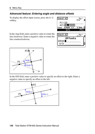
![Menu Key 5
Settings 5.1
To display the Settings menu, press [2] or select
Settings on the MENU screen.
Use this menu to configure the initial job settings.
Some job settings, specified in the following
sections, cannot be changed once a job is
created. If any of these settings are changed while
a job is open, a confirmation screen appears,
asking you to create a new job with the new
settings, or to work with those settings without
recording any data. For more information, see
Settings, page 209.
Angle 51.1
To open the Angle menu, press [1] or select
Angle in the Settings menu.
VA zero Zenith/Horizon/Compass
The VA zero job setting cannot be changed once a job is created.
Resolution For DTM-552, 0.5"/1"/5" or 0.1 mgon/0.2 mgon/1 mgon
For DTM-532 and DTM-522, 1"/5"/10" or
0.2 mgon/1 mgon/2 mgon
HA corr OFF/ON
When this field is set to ON, ACH and Trunnion axis compensation is applied to
horizontal angle readings.
HA 0 to BS/Azimuth
The HA job setting cannot be changed once a job is created.
When this field is set to Azimuth, the horizontal angle (HA) that appears and
recorded is in Azimuth value. When this field is set to 0 to BS, HA is in HA zero to
BS value.
Total Station DTM-502 Series Instruction Manual 131](https://image.slidesharecdn.com/nikon-dtm-502instruction-manual-english-110426153220-phpapp01/85/Nikon-DTN502-instruction-manual-english-151-320.jpg)
![5 Menu Key
Distance 51.2
To open the Distance menu, press [2] or select
Distance in the Settings menu.
Scale Numeric value between
0.999600 and 1.000400
T-P corr. ON/OFF
Sea Level ON/OFF
C&R corr. OFF/0.132/0.200
The Scale, T-P corr., Sea Level, and C&R corr. job settings cannot be changed once
a job is created.
Temperature and Pressure corrections
SD Slope dist. (before adj.)
SD' Slope dist. (after adj.)
K Compensation coefficient
P Pressure (hPa)
T Temperature (°C)
10000.0
106 × P × ⎛ -------------------------------------------- ⎞ -
⎝ 13.5951 × 980.665⎠
K = 275 – ---------------------------------------------------------------------------
237 + T
K
SD' = ⎛ 1 + --------------------⎞ × SD
-
⎝ 1000000⎠
Sea Level correction
HD Horizontal dist. (before adj.)
HD' Horizontal dist. (after adj.)
ZSTN Instrument-Z
Re 6370 km
HD × R e
HD' = ------------------------
R e + Z STN
132 Total Station DTM-502 Series Instruction Manual](https://image.slidesharecdn.com/nikon-dtm-502instruction-manual-english-110426153220-phpapp01/85/Nikon-DTN502-instruction-manual-english-152-320.jpg)
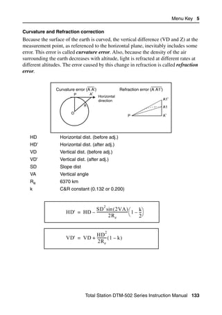
![5 Menu Key
Coordinate 51.3
To open the Coordinate menu, press [3] or select
Coord. in the Settings menu.
Order NEZ/ENZ
Label XYZ/YXZ/NEZ(ENZ)
AZ North/South
The Order and AZ job settings cannot be changed once a job is created.
Power saving 51.4
To open the Power Save menu, press [4] or select
PwrSave in the Settings menu.
Main Unit OFF/5min/10min/30min
EDM Unit OFF/At Once/0.1min/
0.5min/3min/10min
Sleep OFF/1min/3min/5min
Communications 51.5
To open the Communication menu, press [5] or
select Comm. in the Settings menu.
Ext.Comm NIKON/SET
Baud 1200/2400/4800/9600/
19200/38400bps
Length 7/8
Parity EVEN/ODD/NONE
Stop bit 1/2
Stakeout 51.6
Press [6] or select Stakeout in the Settings
menu to open the Stakeout menu.
Add PT Integer between 1 and 999,999
This field sets the default point number to record observed data in stakeout.
134 Total Station DTM-502 Series Instruction Manual](https://image.slidesharecdn.com/nikon-dtm-502instruction-manual-english-110426153220-phpapp01/85/Nikon-DTN502-instruction-manual-english-154-320.jpg)
![Menu Key 5
LG Dist 0 to 9.99 m (32.8 ft)
1Hz
3 Hz (In) 10 Hz (Out)
slightly faster very fast
“LG dist”
Design Pt
If SIGNAL-LOW is detected at the instrument, the Lumi-guide flashes very slowly
(0.5 Hz).
The LG distance guide provides the rodman with approximate In/Out information to
the design point in Stakeout, by changing the speed at which the Lumi-guide
indicator flashes.
Unit 51.7
To open the Unit menu, press [7] or select Unit in
the Settings menu.
Angle DEG (Degree)
GON (GON)
MIL (Mil6400)
Distance Meter/US-Ft/I-F
If you select US-Ft or I-Ft, an additional settings
screen appears. Use this screen to specify
whether to display values in Decimal-Ft or
Ft-Inch.
Temp °C (Celsius)
°F (Fahrenheit)
Press hPa/mmHg/inHg
The Angle, Distance, Temp, and Press job settings cannot be changed once a job is
created.
Total Station DTM-502 Series Instruction Manual 135](https://image.slidesharecdn.com/nikon-dtm-502instruction-manual-english-110426153220-phpapp01/85/Nikon-DTN502-instruction-manual-english-155-320.jpg)
![5 Menu Key
Recording 51.8
To open the Rec menu, press [8] or select Angle
in the Settings menu.
Store DB RAW/XYZ/RAW+XYZ
This setting determines whether raw
and/or coordinate data is stored
when you record SS, CP, or SO
records in the Basic Measurement
Screen (BMS) or Stakeout screen.
Rec LG ON/OFF
If you set this field to ON, when you record a point from the BMS, the
Lumi-guide is turned on for two seconds.
Data Rec Internal/COM
Set this field to COM to output data on the COM port when you press
[ENT] in the BMS or a Stakeout screen. The data is not stored to the job
file. For more information, see Outputting data to the COM port,
page 100.
Others settings 51.9
To open the Others menu, press [9] or select
Other in the Settings menu.
XYZ disp Fast/Norm/Slow/+ENT
Defines speed to move to the next
screen after showing XYZ of the
input PT
2nd Unit None/Meter/US-Ft/I-Ft
When the Secondary unit is set to a unit, an extra display screen is
available in the BMS, stakeout observation screens, and 2-pt
reference line screens. The extra screen shows the HD, VD, and SD in
the secondary unit.
If you select US-Ft or I-Ft, an additional settings
screen appears. Use this screen to specify
whether to display values in Decimal-Ft or Ft-
Inch.
136 Total Station DTM-502 Series Instruction Manual](https://image.slidesharecdn.com/nikon-dtm-502instruction-manual-english-110426153220-phpapp01/85/Nikon-DTN502-instruction-manual-english-156-320.jpg)
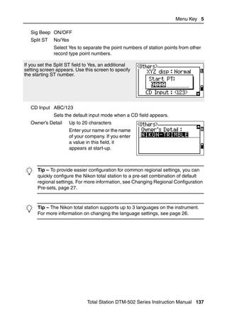
![5 Menu Key
Data 5.2
Use the Data menu to view or edit records. To
display the Data menu, press [4] on the MENU
screen.
Viewing records 52.1
You can view data at any time, even in an observation screen or while entering
points.
Viewing raw data
To show the raw data records in a list, press [1] on
the Data menu screen.
When you first view the raw data, the last four raw
records in the current job are displayed. Use [^] or
[v] to scroll through the records.
To see detailed information for the selected
records, press [ENT].
To return to the record list, press [ESC].
SS, CP, F1, F2 records
Raw SS, CP, F1, and F2 records contain PT, HT, CD, HA, VA, and SD fields.
SS records are sideshots (topo shots). All shots from the Basic Measurement Screen
(BMS) are stored as SS records.
CP records are shots taken in the Angle or Repeat menus, or in the BMS. For more
information, see Recording a foresight point after repeat angle measurement,
page 60, and Recording data from any observation screen, page 99.
F1 and F2 records are Face-1 and Face-2 measurements.
When the Store DB setting is set to RAW+XYZ, press [DSP] to switch between the
first screen (showing HA, VA, SD, PT, and HT) and the second screen (showing X,
Y, Z, PT, and CD).
Coordinates are not available in F1 or F2 records.
138 Total Station DTM-502 Series Instruction Manual](https://image.slidesharecdn.com/nikon-dtm-502instruction-manual-english-110426153220-phpapp01/85/Nikon-DTN502-instruction-manual-english-158-320.jpg)
![Menu Key 5
When you take more than one measurement to the same point and choose to
overwrite the XYZ data, the old raw record becomes raw data only. As a result, only
one SS(RAW) record keeps its corresponding SS(XYZ) record. Other SS(RAW)
records to the same point no longer have coordinates available.
ST records
ST (station) records contain ST, HI, BS, and AZ fields.
Press [DSP] to switch between the first screen (showing ST, HI, BS, and AZ) and the
second screen (showing X, Y, Z, PT, and CD).
When you assign a new ST point name in MENU > Stn Setup > Quick, the
coordinates of the station is recorded as (0, 0, 0).
SO records
SO records are stakeout shots. These are shots recorded in stakeout functions.
When the Store DB setting is set to RAW+XYZ, press [DSP] to switch between the
first screen (showing HA, VA, SD, PT, and HT), the second screen (showing X, Y,
Z, PT, and CD), and the third screen (showing dX, dY, dZ, PT, and CD).
The dX, dY, and dZ fields store the difference between the stakeout shot’s actual
position and its planned position. These fields are downloaded as comment records
in Nikon RAW format.
CO records
A CO record is a comment added to the job from the system.
For example, when you change the Stn-Z using
the Remote Benchmark function, or you reset the
horizontal angle using the BSCheck function, the
system writes a comment record.
When you input a Stn-XYZ by Base-XYZ
function, the recorded station appears as a
comment record.
Total Station DTM-502 Series Instruction Manual 139](https://image.slidesharecdn.com/nikon-dtm-502instruction-manual-english-110426153220-phpapp01/85/Nikon-DTN502-instruction-manual-english-159-320.jpg)
![5 Menu Key
SY records
When you complete a station setup, a SY record is
stored. This record contains the Temperature,
Pressure, and Prism Constant values.
RM records
When you record measurements in RDM (Cont)
or RDM (Rad), they are labeled as RM records.
Each RM record consists of two screens.
Press [DSP] to switch between the first screen
(showing From, To, rHD, and rVD) and the
second screen (showing rAZ, rSD, rV%, and
rGD).
When you download data in Nikon RAW format,
RM records are output as comment (CO) records.
AR records
An AR record stores an area and perimeter calculation.
When you download data in Nikon RAW format,
AR records are output as comment (CO) records.
View coordinate data
When you press [2] or select XYZ data in the
Data menu, coordinate data appears in a list, with
the newest record at the bottom of the screen. Use
[^] or [v] to scroll through the records. Use [<] or [>]
to move up or down one page.
140 Total Station DTM-502 Series Instruction Manual](https://image.slidesharecdn.com/nikon-dtm-502instruction-manual-english-110426153220-phpapp01/85/Nikon-DTN502-instruction-manual-english-160-320.jpg)
![Menu Key 5
Press [ENT] to see more detailed information about
the selected record.
The header (XYZ,YXZ,NEZ, or ENZ) depends on the Coord. Label setting in MENU
> Settings > Coord. For more information, see Coordinate, page 134.
UP, MP, CC, and RE records
All coordinate records contain PT, CD, X, Y, and Z fields.
UP records are uploaded point coordinates. MP records are manually input point
coordinates. CC records are points calculated in Cogo, and RE records are points
calculated in Resection.
When the Store data setting is set to RAW+XYZ or to XYZ, shots in the BMS (SS
records), in various O/S functions (SS records), in 2Pt-RefLine and Arc-RefLine in
PRG (SS records) and in some Stakeout functions (SO records) store coordinate
records as well. The format of the data is the same as other coordinate records.
View records by station
To view records by station, press [3] or select
ST->SS/SO/CP in the Data menu.
A list of all stations appears.
Use [^] or [v] to highlight the station name that you
want to view. Use [<] or [>] to move up or down one
page.
To view detailed information about the selected
station, press [ENT].
Total Station DTM-502 Series Instruction Manual 141](https://image.slidesharecdn.com/nikon-dtm-502instruction-manual-english-110426153220-phpapp01/85/Nikon-DTN502-instruction-manual-english-161-320.jpg)
![5 Menu Key
To display all the observation data from the
selected station in chronological order, press [ENT]
again.
Detailed data is as for raw data. For detailed information about each point type and
format, see Viewing raw data, page 138.
Deleting records 52.2
Deleting raw records
In the RAW screen, use [^] or [v] to highlight the
record that you want to delete. Then press the DEL
softkey.
A confirmation screen appears. To delete the
selected record, press [ENT] or the Yes softkey.
If the Store DB setting is set to Both, the system also deletes the corresponding
coordinate data when you delete an SS, SO, or CP record.
You can also delete raw data by pressing the
DEL softkey in the detailed display screen for the
record.
142 Total Station DTM-502 Series Instruction Manual](https://image.slidesharecdn.com/nikon-dtm-502instruction-manual-english-110426153220-phpapp01/85/Nikon-DTN502-instruction-manual-english-162-320.jpg)
![Menu Key 5
Deleting coordinate records
In the XYZ screen, use [^] or [v] to highlight the
record that you want to delete. Then press the DEL
softkey.
A confirmation screen appears.
To delete the selected record, press [ENT] or the
Yes softkey.
To cancel the deletion of data, press [ESC] or the
No softkey.
You can also delete coordinate data by pressing
the DEL softkey in the detailed display screen for
the record.
If the record that you want to delete is referred by
an ST record, a confirmation message appears.
Deleting station records
In the Station screen, use [^] or [v] to highlight the
record that you want to delete. Then press the DEL
softkey.
Total Station DTM-502 Series Instruction Manual 143](https://image.slidesharecdn.com/nikon-dtm-502instruction-manual-english-110426153220-phpapp01/85/Nikon-DTN502-instruction-manual-english-163-320.jpg)
![5 Menu Key
A confirmation screen appears.
Press [ENT] or the Yes softkey to delete the
selected record.
A reconfirmation screen appears. Press the DEL
softkey to confirm deletion.
There is no undelete function on the instrument.
Before you press the DEL softkey, make sure that
you have selected the correct station record. You
cannot press [ENT] in this screen.
All observations from the station that you selected
are deleted.
When you delete a ST record in the raw data view or the station data view, all the
observation data from the station is also deleted.
Editing records 52.3
For any point record, you can edit the point name (PT), feature code (CD), height of
target (HT), height of instrument (HI), backsight point (BS), and backsight azimuth
(AZ).
You cannot edit the CD field for SO, F1, or F2 records.
You cannot edit the HA, VA, or SD values.
Editing raw records
1. Do one of the following:
– In the RAW screen, highlight the record
that you want to edit. Then press the Edit
softkey.
144 Total Station DTM-502 Series Instruction Manual](https://image.slidesharecdn.com/nikon-dtm-502instruction-manual-english-110426153220-phpapp01/85/Nikon-DTN502-instruction-manual-english-164-320.jpg)
![Menu Key 5
– In the detailed data screen, press the Edit
softkey.
2. Use [^] or [v] to highlight a field. Then modify
the value in the selected field.
When you change the HT of an SS, SO, or CP measurement record, its Z
coordinate is recalculated.
3. When you press [ENT] on the last line of the edit
screen, a confirmation screen appears.
4. Do one of the following:
– To accept the changes and return to the
data view screen, press [ENT] or the Yes
softkey.
– To return to the edit screen, press [ESC] or
the No softkey.
Editing coordinate records
You can edit PT, CD, and coordinate values in coordinate records.
You cannot edit the coordinate record for the current station.
Total Station DTM-502 Series Instruction Manual 145](https://image.slidesharecdn.com/nikon-dtm-502instruction-manual-english-110426153220-phpapp01/85/Nikon-DTN502-instruction-manual-english-165-320.jpg)
![5 Menu Key
1. Do one of the following:
– In the XYZ screen, use [^] or [v] to highlight
the record that you want to edit. Then press
the Edit softkey.
– In the detailed data screen, press the Edit
softkey.
2. Use [^] or [v] to highlight a field. Then modify
the value in the selected field.
3. To finish editing, press [ENT] in the CD field.
A confirmation screen appears.
4. Do one of the following:
– To accept the changes and return to the
data view screen, press [ENT] or the Yes
softkey.
– To go back to the edit screen, press [ESC] or
the No softkey.
146 Total Station DTM-502 Series Instruction Manual](https://image.slidesharecdn.com/nikon-dtm-502instruction-manual-english-110426153220-phpapp01/85/Nikon-DTN502-instruction-manual-english-166-320.jpg)
![Menu Key 5
Editing station records
Note – The system will not recalculate measurements if you change the station
record. All coordinate and raw data observed from an edited station record must be
recalculated in your postprocessing software.
In the RAW screen, use [^] or [v] to highlight the
station record that you want to edit. Then press the
Edit softkey.
You can edit any field in the ST record, but the
instrument does not recalculate any measurements
from this station.
Press [ENT] in the AZ field to confirm the change.
If you change the ST or HI values, the coordinates of observation points are not
recalculated. A comment record is stored to record the change. The following
example shows a comment record for a changed HI value:
CO,HI changed at ST:9012 Old HI= 1.3456m
If you change the BS or AZ values, raw records are not recalculated. A comment
record is stored to record the change.
Searching records 50.1
You can search for records by their type, point name, code, or by any combination
of these values.
Searching raw records
In the RAW screen, press the Srch softkey to
access the raw data search function.
Total Station DTM-502 Series Instruction Manual 147](https://image.slidesharecdn.com/nikon-dtm-502instruction-manual-english-110426153220-phpapp01/85/Nikon-DTN502-instruction-manual-english-167-320.jpg)
![5 Menu Key
To find a point by name, enter the name in the PT
field and press [ENT] twice.
You can use the asterisk (*) as a wildcard. For
example, when you enter 30* in the PT field, the
search matches the points named 300, 301, 302,
3000A2, and 3010.
To search by point type, move to the Type field
and use [<] or [>] to change the selected point
type. The options are ALL, ST, SS, SO, CP, CO,
CO(SY), and CO(RDM).
If you selected ST, SO, F1, or F2 in the Type field, you do not have to enter a value
in the CD field. Press [ENT] in the PT field to start the search.
If you selected CO, CO(SY), or CO(RDM) in the Type field, you cannot enter a value
in the PT or CD fields. Press [ENT] in the Type field to start the search.
If more than one point matches the search criteria,
the matching points are displayed in a list.
Use [^] or [v] to highlight the point you want to use.
Then press [ENT] to select it.
Detailed data for the selected record appears.
Press the DSP softkey to change the fields shown.
Press [ESC] to return to the list.
148 Total Station DTM-502 Series Instruction Manual](https://image.slidesharecdn.com/nikon-dtm-502instruction-manual-english-110426153220-phpapp01/85/Nikon-DTN502-instruction-manual-english-168-320.jpg)
![Menu Key 5
If no point matches the specified criteria, an error
screen appears. Press any key to return to the
data screen.
Searching coordinate records
In the XYZ screen, press the Srch softkey to
access the XYZ data search function.
To find a coordinate by name, enter the name in
the PT field and press [ENT] twice.
You can use the asterisk (*) as a wildcard. For
example, when you enter 500* in the PT field,
the search matches the points named 500, 500-1,
500-A, and 5000.
To search by point type, move to the Type field
and use [<] or [>] to change the selected point
type. The options are ALL, MP, UP, CC, and RE.
Total Station DTM-502 Series Instruction Manual 149](https://image.slidesharecdn.com/nikon-dtm-502instruction-manual-english-110426153220-phpapp01/85/Nikon-DTN502-instruction-manual-english-169-320.jpg)
![5 Menu Key
If more than one point matches the search criteria,
the matching points are displayed in a list.
Use [^] or [v] to highlight the point you want to use.
Press [ENT] to select it.
Detailed data for the selected record appears.
Press the DSP softkey to change the fields shown.
Press [ESC] to return to the list.
If no point matches the specified criteria, an error
screen appears. Press any key to return to the
data screen.
Entering coordinates 50.2
In the XYZ screen, press the Input softkey to
display a new input point screen.
The PT field defaults to the last recorded PT + 1,
but you can change the value shown.
Enter the PT and CD and then press [ENT] to enter
coordinates.
Use the numeric keys to enter the coordinates.
Press [ENT] or [v] in each field to move to the next
field.
When you press [ENT] in the CD field, the point is
stored as an MP record.
150 Total Station DTM-502 Series Instruction Manual](https://image.slidesharecdn.com/nikon-dtm-502instruction-manual-english-110426153220-phpapp01/85/Nikon-DTN502-instruction-manual-english-170-320.jpg)
![Menu Key 5
After you have recording a point, the next point
input screen is shown with the updated default PT.
You can record NE, NEZ, or Z-only data to the database.
Point name list and code list 50.3
The instrument stores two list files: a list of PT names and a list of CD names. The
structure and functionality of these files is the same.
• The PT name list is useful if you have to handle more than one patterns of point
names in the field. For example, you may need to use points named 1, 2, 3 …, as
well as points named A1, A2, A3 ….
• The code list is a prepared list of feature codes. You can use it to store your own
codes.
Press [4] or select PT name List in the Data
menu to open the point name list.
Press [5] or select Code list to open the code
list.
The point or code names and layers are shown in
alphabetic order. Use the four softkeys to
customize the list.
You can store up to 254 points, codes, or layers in each list.
Each list entry can be up to 16 characters long.
You can use the first character search to find a point, code, or layer in the list. In the
list screen, enter the first character of the name you want to find to jump to that part
of the list. For more information, see Advanced feature: Searching for a code by
using the first character, page 51.
Total Station DTM-502 Series Instruction Manual 151](https://image.slidesharecdn.com/nikon-dtm-502instruction-manual-english-110426153220-phpapp01/85/Nikon-DTN502-instruction-manual-english-171-320.jpg)
![5 Menu Key
Deleting points, codes, or layers
In the point or code list, use [^] or [v] to highlight
the item you want to delete. Then press the DEL
softkey.
A confirmation screen appears. Press [ENT] or the
Yes softkey to delete the item.
Press [ESC] or the No softkey to cancel the
deletion.
To delete a whole layer, highlight the layer name
in the list and press the DEL softkey. All codes
and layers in the selected layer are deleted.
Editing an item in the point list or code list
Use [^] or [v] to highlight the item that you want to
edit. Then press the Edit softkey.
An editing screen appears. For points, the Edit
Item screen appears. It contains only the PT field.
For codes, the Edit Code screen appears,
containing the CD field and the REC field.
Edit the text shown and then press [ENT].
152 Total Station DTM-502 Series Instruction Manual](https://image.slidesharecdn.com/nikon-dtm-502instruction-manual-english-110426153220-phpapp01/85/Nikon-DTN502-instruction-manual-english-172-320.jpg)
![Menu Key 5
A confirmation screen appears. Press [ENT] or the
Yes softkey to accept the changes and update the
list.
Edit code list
The Edit Code screen has two fields. The CD field
contains the text that appears in the list screen.
The REC field is optional. It contains the text that
is stored in the job. If you leave the REC field
blank, the value in the CD field is used.
You can use the REC field to use familiar words or
codes on the screen, but store a numeric code in
the job. For example, if you set the CD field to
MANHOLE and the REC field to 1155, the text
MANHOLE appears on the screen, but the code
1155 is stored.
If you press the Edit softkey when a layer name
appears, only the Lyr field appears. To save
changes to the layer name, press [ENT] in the Lyr
field.
Adding a point name
In the point list, press the Add softkey to add a
new point name to the current layer.
Total Station DTM-502 Series Instruction Manual 153](https://image.slidesharecdn.com/nikon-dtm-502instruction-manual-english-110426153220-phpapp01/85/Nikon-DTN502-instruction-manual-english-173-320.jpg)
![5 Menu Key
Enter a new point name and then press [ENT].
The point name is added to the current layer and
the list is updated.
Adding a code
In the code list, press the Add softkey to add a
new feature code to the current layer.
Enter the feature code in the CD field. Press
[MODE] to change between alphabetic and numeric
input mode.
You can use the REC field to define a numeric
identifier for each feature code. This is optional: If
there is a value in the REC field, this value is
stored. If you leave the REC field blank, the CD
value is stored.
Press [ENT] to add the new code and update the
code list.
154 Total Station DTM-502 Series Instruction Manual](https://image.slidesharecdn.com/nikon-dtm-502instruction-manual-english-110426153220-phpapp01/85/Nikon-DTN502-instruction-manual-english-174-320.jpg)
![Menu Key 5
Adding a layer
1. In the point or code list, press the Layer
softkey.
2. Enter the name of the new layer.
3. To change between alphabetic and numeric
input mode, press [MODE]. To store the new
layer, press [ENT].
The new layer is added to the list in alphabetic
order.
Communication 5.1
Use the Communication menu to download or
upload data. To display the Communication menu,
press [5] or select Comm. on the MENU screen.
Total Station DTM-502 Series Instruction Manual 155](https://image.slidesharecdn.com/nikon-dtm-502instruction-manual-english-110426153220-phpapp01/85/Nikon-DTN502-instruction-manual-english-175-320.jpg)
![5 Menu Key
Downloading data 51.1
To go to the download settings screen, press [1] or
select Download in the Communication menu.
Format NIKON
SDR2x
SDR33
Data RAW
Coordinate
To display the total number of records that will be
downloaded, press [ENT] in the Data field.
As each record in the current job is output from
the instrument (downloaded), the current line
number is updated.
After downloading is completed, you can choose
to delete the current job.
To delete the current job, press [4]. To return to the
Basic Measurement Screen (BMS), press [ESC] or
the Abrt softkey.
Uploading coordinate data 51.2
To upload coordinate data from a computer, press
[2] or select Upload XYZ in the Communication
menu.
156 Total Station DTM-502 Series Instruction Manual](https://image.slidesharecdn.com/nikon-dtm-502instruction-manual-english-110426153220-phpapp01/85/Nikon-DTN502-instruction-manual-english-176-320.jpg)
![Menu Key 5
The default data format appears. To change the
order of data fields, press the Edit softkey. For
more information, see Advanced feature: Editing
the data order for upload, page 158.
Otherwise, just press [ENT].
Press the Job softkey to go to the Job Manager screen. For more information, see
Job Manager, page 112.
To change the communication settings, press the
Comm softkey. The serial port settings must match
the settings used by the terminal software on the
computer.
Use an RS-232C cable to connect the instrument
to the computer.
The Free space field shows the number of points
that can be stored.
Press [ENT] to put the instrument in receive mode.
Then use the Send Text File command in the
terminal program on the computer to start sending data.
In the terminal program, set flow control to Xon/Xoff.
As each point is received by the instrument, the
value in the Records field is incremented.
If you press [ESC] during data upload, the upload is canceled and the display returns
to the Communication menu. Records that were received before you pressed [ESC]
are stored in the job.
The system truncates any code that is longer than 16 characters.
Duplicate points
If the existing point is a UP, CC, or MP record, and it is not referred to by any ST or
BS, it is automatically overwritten by the uploaded point. No error message appears.
Total Station DTM-502 Series Instruction Manual 157](https://image.slidesharecdn.com/nikon-dtm-502instruction-manual-english-110426153220-phpapp01/85/Nikon-DTN502-instruction-manual-english-177-320.jpg)
![5 Menu Key
Advanced feature: Editing the data order for upload
1. To open the Data Fields screen, press the
Edit softkey.
2. To move between the fields, press [<] or [>].
3. To change the selected item in a field, use the
and softkeys. The options are PT, N, E,
Z, CD, or blank.
4. To save your changes and return to the
previous screen, press the Save softkey.
For example, if your original data is as follows:
1, UB, 30.000, 20.000, L1
and you set the data fields to PT N E CD, then the uploaded data is:
PT=1, N=30.000, E=20.000, CD=L1
Uploading coordinates without points
You can upload data without points. If you do not include a point in the format
definition, each line of data is automatically assigned the next available point
number. To help you to select points in the field, make sure that you store an
identifier in the CD field.
The data format cannot include duplicate items. Use PT, N, E, Z and CD once each
in the data format.
To skip some items in your original file, set the corresponding field to blank.
Uploading a point name list or code list 50.1
When you upload a code list, it always replaces the existing code list on the
instrument.
To upload a point name list via cable, press [3] or select PT List in the
Communication menu.
158 Total Station DTM-502 Series Instruction Manual](https://image.slidesharecdn.com/nikon-dtm-502instruction-manual-english-110426153220-phpapp01/85/Nikon-DTN502-instruction-manual-english-178-320.jpg)
![Menu Key 5
To upload a code list, press [4] or select Code
List.
Connect the RS-232C cable.
Start a terminal program on the computer.
To put the instrument into receive mode, press
[ENT] or the OK softkey.
The counter is updated as each line in the list is
stored.
You can store up to 254 codes or point names.
If a code or point name is longer than 16 characters, it is truncated.
1sec-Keys 5.1
Use the 1sec-Keys menu to configure the settings
for the one-second keys, [MSR], [DSP], [USR], [S-O],
and [DAT]. To access this menu, press [6] or select
1sec-Keys in the MENU screen.
[MSR] key settings 51.1
To change settings for the [MSR1] and [MSR2] keys,
press [1] or select [MSR] in the 1sec-Keys menu.
Total Station DTM-502 Series Instruction Manual 159](https://image.slidesharecdn.com/nikon-dtm-502instruction-manual-english-110426153220-phpapp01/85/Nikon-DTN502-instruction-manual-english-179-320.jpg)
![5 Menu Key
There are two [MSR] keys:
– To change the settings for the [MSR1] key,
press [1] or select MSR1.
– To change the settings for the [MSR2] key,
press [2] or select MSR2.
Each [MSR] key has five settings.
In the Const and AVE fields, use the numeric keys
to enter values. In the other fields, use [<] or [>] to
change the settings.
B Tip – Youone second. the settings screen by holding down [MSR1] or
[MSR2] for
can also access
[DSP] key settings 51.2
To change the display items in the BMS and in
Stakeout observation screens, press [2] or select
[DSP] in the 1sec-Keys menu.
To move the cursor, use [<], [>] , [^], or [v]. To change
the display item, press either the softkey or the
softkey.
To save the changes, press [ENT] at the last line of
<DSP3> or press the Save softkey.
B Tip –second. also access the DSP settings screen by holding down [DSP] for
one
You can
160 Total Station DTM-502 Series Instruction Manual](https://image.slidesharecdn.com/nikon-dtm-502instruction-manual-english-110426153220-phpapp01/85/Nikon-DTN502-instruction-manual-english-180-320.jpg)
![Menu Key 5
[USR] key settings 51.3
To change the functions that are assigned to the
[USR1] and [USR2] keys, press [3] or select [USR] in
the 1sec-Keys menu.
There are two [USR] keys. The function that is
assigned to each key appears beside the key name.
– To change the settings for the [USR1] key,
press [1] or select USR1.
– To change the settings for the [USR2] key,
press [2] or select USR2.
In the Select Functions screen, the asterisk (*)
indicates the function that is currently assigned to
the key.
To highlight a function, use [^] or [v]. To assign that
function to the selected [USR] key, press [ENT].
[S-O] key settings 51.4
To enter the Stakeout settings screen, press [4] or
select [S-O] in the 1sec-Keys menu.
There are two Stakeout settings. For more
information, see Stakeout, page 134.
Total Station DTM-502 Series Instruction Manual 161](https://image.slidesharecdn.com/nikon-dtm-502instruction-manual-english-110426153220-phpapp01/85/Nikon-DTN502-instruction-manual-english-181-320.jpg)
![5 Menu Key
[DAT] key settings 51.5
1. To change the settings for the [DAT] key, press
[5] or select [DAT] in the 1sec-Keys menu.
The asterisk (*) indicates the currently
selected view format.
2. To move the cursor, use [^] or [v].
3. To change the format displayed by [DAT], press
[ENT].
Calibration 5.1
Use the Calibration screen to calibrate the
instrument. To open the Calibration screen, press
[7] or select Calibrat. on the MENU screen.
For more information, see Adjusting, page 168.
Time 5.2
Use the Date & Time screen to set the current date
and time.
1. To open the Date & Time screen, press [8] or
select Time on the MENU screen.
The current date and time settings are
displayed.
2. Enter the date in Year-Month-Day format. For
example, to change the date to June 18, 2002,
press
[2] [0] [0] [2] [ENT] [6] [ENT] [1] [8] [ENT].
162 Total Station DTM-502 Series Instruction Manual](https://image.slidesharecdn.com/nikon-dtm-502instruction-manual-english-110426153220-phpapp01/85/Nikon-DTN502-instruction-manual-english-182-320.jpg)
![Menu Key 5
If the highlighted part of the field (for example, the year) is already correct, you
can just press [ENT] to use the current value. For example, if the date is already set
to June 24, 2002, and you want to change the date to June 18, 2002, press [ENT]
[ENT] [1] [8] [ENT].
3. To move to the Time field, press [ENT] in the
Date field.
4. Enter the time in 24-hour format. For example,
to set the time to 4:35 PM, press
[1] [6] [ENT] [3] [5] [ENT].
5. Do one of the following:
– To finish setting the date and time, press [ENT] in the Minutes field.
– To cancel the input, press [ESC].
Total Station DTM-502 Series Instruction Manual 163](https://image.slidesharecdn.com/nikon-dtm-502instruction-manual-english-110426153220-phpapp01/85/Nikon-DTN502-instruction-manual-english-183-320.jpg)
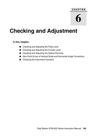
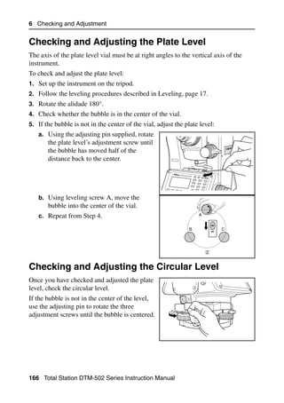
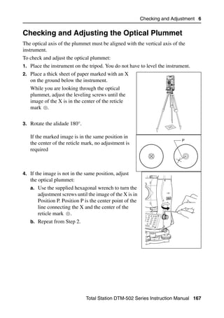
![Checking and Adjustment 6
To set the parameters for trunnion axis error
compensation, establish two targets at a Second
horizontal distance of at least 30 m from the target
instrument. The first target should be
placed on the horizontal plane and the
second should be more than 30° above the
horizontal plane. First
Before you set the trunnion axis target
compensation value, you must complete
three sets of F1/F2 observations to these
two points.
Even if you complete the second step, the
instrument cannot store a trunnion axis
error compensation of more than 30". If the error is more than 30", the instrument
needs a mechanical check.
To enter the calibration screen, press [MENU] and [7].
First step
1. Take an F1 measurement to a target on the
horizon. Press [ENT].
The vertical angle is shown in the
V0 dir= Horiz setting.
VA1 Face-1 vertical angle (tilt-off value)
HA1 Face-1 horizontal angle (tilt-off value)
X1 Face-1 X axis tilt value
Y1 Face-1 Y axis tilt value
If you sight a target that has a VA of more than
3°, a warning message flashes on the third
line.
Total Station DTM-502 Series Instruction Manual 169](https://image.slidesharecdn.com/nikon-dtm-502instruction-manual-english-110426153220-phpapp01/85/Nikon-DTN502-instruction-manual-english-189-320.jpg)
![6 Checking and Adjustment
When you have taken the measurement, the
message on the bottom line changes from DO
NOT TOUCH to Turn to F2.
2. Take an F2 measurement to the same target.
Press [ENT].
VA2 Face-2 vertical angle (tilt-off value)
HA2 Face-2 horizontal angle (tilt-off value)
X2 Face-2 X axis tilt value
Y2 Face-2 Y axis tilt value
When the observation on F2 is completed, four
parameters are displayed.
3. Do one of the following:
– To return to the first observation screen,
press [ESC] or the Redo softkey.
– To set parameters on the instrument, press
[ENT] or the OK softkey.
4. To go to the second step (trunnion axis compensation), press the Trun softkey.
If the HA corr. setting is set to OFF, the ACH
parameter is not applied to horizontal angle
readings. If this setting is set to ON, both of the
ACH and trunnion-axis parameters are applied to
HA. If you do not complete the second step, the
trunnion-axis parameter remains set to zero, and
only the ACH parameter is applied. For more
information, see Angle, page 131.
If ACV, ACH, X, or Y is out of range, OVER
appears. Press any key to return to the first observation screen.
170 Total Station DTM-502 Series Instruction Manual](https://image.slidesharecdn.com/nikon-dtm-502instruction-manual-english-110426153220-phpapp01/85/Nikon-DTN502-instruction-manual-english-190-320.jpg)
![Checking and Adjustment 6
Second step
1. Sight the second target that is placed more
than 30 degrees above the horizontal plane.
2. Press [ENT] to take angle measurements in the
following order:
– Face-2 to P2
– Face-1 to P2
– Face-1 to P1 (Horizontal)
– Face-2 to P1 (Horizontal)
– Face-2 to P2
– Face-1 to P2
– Face-1 to P1 (Horizontal)
– Face-2 to P1 (Horizontal)
– Face-2 to P2
– Face-1 to P2
The tolerance in angle reading to each
direction is 10". To maintain the accuracy of
the instrument, you must take shots with
extreme care. If the dHA to the same direction
is more than 10", an error message appears,
and you must remeasure all three sets of
points.
After three sets of F1/F2 observations, the
instrument calculates the trunnion axis
parameter and the updated ACH (the average
of each set).
3. Do one of the following:
– To return to the measurement screen for
the first set of F1 measurements, press [ESC] or the Redo softkey.
– To go to the next set of observations for a more accurate result, press the
Cont softkey. You can record up to ten sets.
– To store the parameter and return to the BMS, press [ENT] or the END softkey.
Total Station DTM-502 Series Instruction Manual 171](https://image.slidesharecdn.com/nikon-dtm-502instruction-manual-english-110426153220-phpapp01/85/Nikon-DTN502-instruction-manual-english-191-320.jpg)
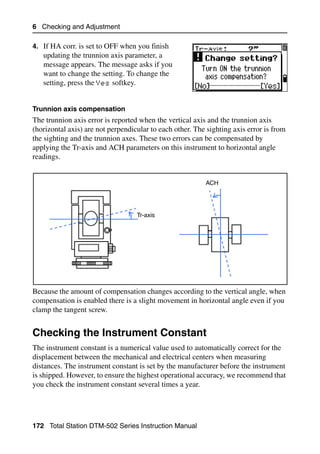
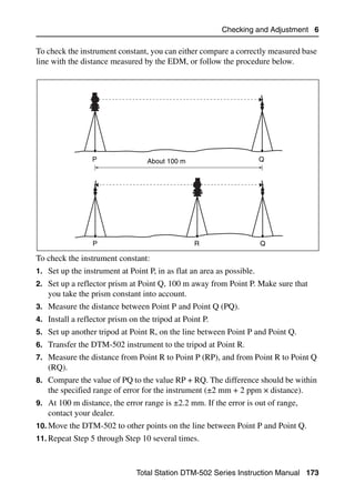
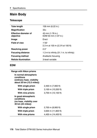
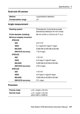
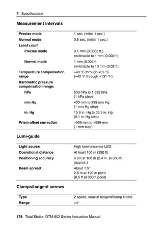
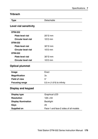
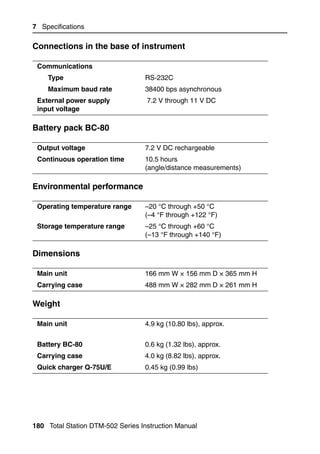
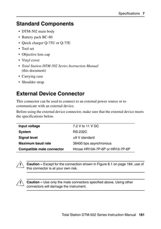
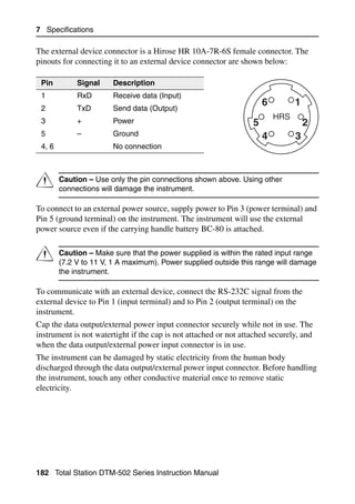
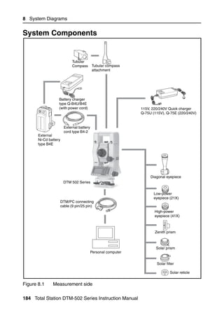
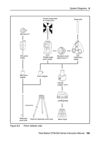
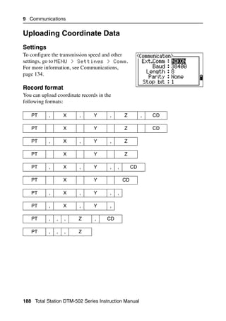
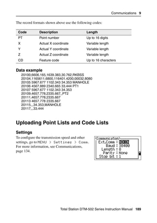
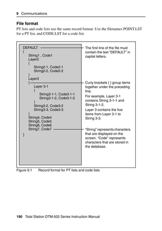
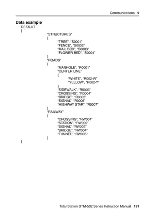
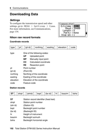
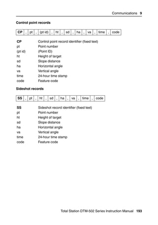
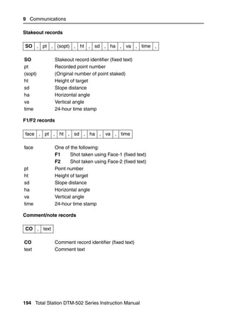
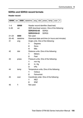
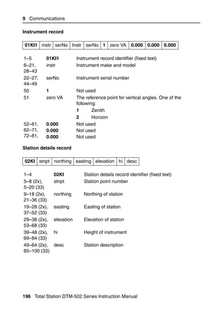
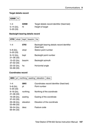
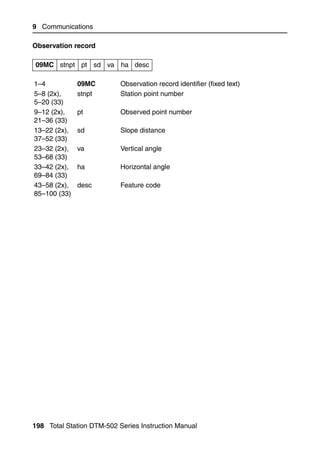
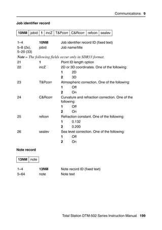
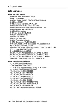
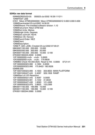
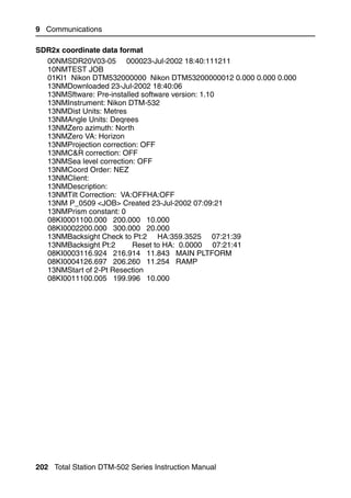
![10 Error Messages
DELETE Stn-XYZ 104.4
You have tried to delete a coordinate record that the current ST or BS refers to. You
must confirm that you want to delete a coordinate record that the current ST or BS
refers to.
To ... Press ...
delete XYZ the DEL softkey
return to the previous screen without deleting XYZ [ESC] or the Abrt softkey
Job Manager 10.5
Cannot Assign 105.1
You have tried to set the current job as the control file.
Press any key to return to the previous screen. Then select a different job.
Can't Create 105.2
There is no space available to create a job or record a point.
Press any key to return to the Job Manager. Then use the DEL softkey to delete old
jobs.
Existing Job 105.3
You have entered an existing job name for a new job.
Press any key and then change the name for the new job.
MAX 32Jobs 105.4
You are trying to create a new job when the maximum number of jobs (32) is
already stored.
Press any key to return to the Job Manager. Then use the DEL softkey to delete old
jobs.
206 Total Station DTM-502 Series Instruction Manual](https://image.slidesharecdn.com/nikon-dtm-502instruction-manual-english-110426153220-phpapp01/85/Nikon-DTN502-instruction-manual-english-226-320.jpg)
![Error Messages 10
Programs 10.6
NO Stn Setup 106.1
You did not perform a station setup or BS check before entering the Programs
function.
To ... Press ...
go to the Stn Setup menu [2] or select Stn Setup
return to the BMS [ESC]
go to the Programs menu [1] or select Continue
C Warning – Selecting Continue does not resume the last ST record. You
should only use the Continue option if you are sure that the previous ST
coordinates and the current HA orientation are correct. Otherwise, records in
the Programs function may not be correct.
XY&Z coordinate are required 106.2
Three-dimensional coordinates are required in S-Plane function.
Press any key to return to the point input screen. Then enter a three-dimensional
point.
Recording Data 10.7
DATA FULL 107.1
The data storage is full.
Press any key to return to the Basic Measurement Screen (BMS). Then:
To ... Go to ...
delete unnecessary data MENU > Data
delete jobs MENU > Job
DUPLICATE PT 107.2
The input PT you are trying to record already exists in the current job. An existing
coordinate record cannot be overwritten by measured data.
Press any key to return to the point input screen. Change PT.
Total Station DTM-502 Series Instruction Manual 207](https://image.slidesharecdn.com/nikon-dtm-502instruction-manual-english-110426153220-phpapp01/85/Nikon-DTN502-instruction-manual-english-227-320.jpg)
![10 Error Messages
Duplicate PT 107.3
The input PT you are trying to record already exists in the current job as an SS, SO,
or CP record. An existing SS, SO, or CP record can be overwritten by measured
data.
To ... Press ...
return to the PT input screen [ESC] or the Abrt softkey
record RAW data and update XYZ data the XYZ softkey
record RAW data only the RAW softkey
No Open Job 107.4
No job is open.
To ... Press ...
open the job list, if there are existing jobs [1] or select Select job
create a new job [2] or select Create job
return to the previous screen [ESC]
NO Stn Setup 107.5
There is no station record in the current job, or a station setup or BS check has not
been done since the program was rebooted.
To ... Press ...
continue recording [1] or select Continue. If there is already
an ST record in the job, the message CO,
Use current orientation
appears.
go to the Stn Setup menu [2] or select STN Setup
return to the previous screen [ESC]
OVER RANGE 107.6
You are trying to record a coordinate with more than 13 digits
Press any key to return to the previous screen. Then check the current ST
coordinate.
208 Total Station DTM-502 Series Instruction Manual](https://image.slidesharecdn.com/nikon-dtm-502instruction-manual-english-110426153220-phpapp01/85/Nikon-DTN502-instruction-manual-english-228-320.jpg)
![Error Messages 10
Searching 10.8
PT Not Found 108.1
There is no point that matches the criteria you entered.
Press any key to return to the point input screen.
This message may appear in any function where the PT/CD is input, such as Station
Setup or Stakeout.
Settings 10.9
Job Settings will be changed 109.1
You have changed one or more of the following job settings:
• VA zero or HA in the Angle screen (see Angle, page 131)
• Scale, T-P, Sea Lvl, or C&R in the Distance screen (see Distance, page 132)
• Coord or Az Zero in the Coordinates screen (see Coordinate, page 134)
• Angle, Dist, Temp, or Press in the Unit screen (see Unit, page 135)
To ... Press ...
discard the changes to the job settings [ESC] or the Abrt softkey. The
current job remains open.
close the current job and save the changes [ENT] or the OK softkey
to the job settings
Note – To record a point using the new settings, create a new job using the new
settings.
Stakeout 10.10
Input Error 1010.1
The point name style used in the Fr field is not the same as the style used in the To
field. For example, the Fr field style is 1, and the To field style is A200.
Press any key to return to the Fr/To input screen. Then re-enter the point name,
using the same naming style in both fields.
Total Station DTM-502 Series Instruction Manual 209](https://image.slidesharecdn.com/nikon-dtm-502instruction-manual-english-110426153220-phpapp01/85/Nikon-DTN502-instruction-manual-english-229-320.jpg)
![10 Error Messages
NO Stn Setup 1010.2
You did not perform a station setup or BS check before entering the Stakeout
function.
To... Press ...
go to the Stn Setup menu [2] or select Stn Setup
return to the Basic [ESC]
Measurement Screen (BMS)
go to the Stakeout menu [1] or select Continue
C Caution – Selecting Continue does not resume the last ST record. You
should only use the Continue option if you are sure that the previous ST
coordinates and the current HA orientation are correct. Otherwise, records in
the Stakeout function may not be correct.
Station Setup 10.11
Calc ST Failed Need additional PT 1011.1
Calculating ST failed in resection. This message may appear after you have deleted
a point the View shots screen.
Press any key to return to the PT input screen. Take another shot to calculate the ST
coordinate.
Same Coordinate 1011.2
The input PT or coordinate is identical to the current station in STN/1:Known, or
the same coordinate or point name/number is found in Resection.
Press any key to return to the PT input screen. Then use a different PT.
210 Total Station DTM-502 Series Instruction Manual](https://image.slidesharecdn.com/nikon-dtm-502instruction-manual-english-110426153220-phpapp01/85/Nikon-DTN502-instruction-manual-english-230-320.jpg)
![Error Messages 10
Space LOW 1011.3
There is not enough space to record a station when you start any of the Station
Setup functions.
To ... Press ...
return to the BMS press [ESC] or the Abrt softkey. Use the DEL
softkey in Job Manager to delete old jobs.
continue press [ENT] or the OK softkey. You may not be able
to record the whole process.
XY-coordinate is required 1011.4
The input point for ST/BS does not have N/E coordinates.
Press any key to return to the PT input screen. Then use a PT that has N/E
coordinates.
Z-coordinate is required 1011.5
The input point for Benchmark does not have a Z coordinate.
Press any key to return to the PT input screen. Then use a PT that has a
Z coordinate.
Total Station DTM-502 Series Instruction Manual 211](https://image.slidesharecdn.com/nikon-dtm-502instruction-manual-english-110426153220-phpapp01/85/Nikon-DTN502-instruction-manual-english-231-320.jpg)


The document is an instruction manual for the Total Station DTM-502 series models DTM-522, DTM-532, and DTM-552, detailing safety warnings, equipment specifications, and operational procedures. It emphasizes the importance of following instructions to prevent personal injury and property damage, while also providing guidelines for battery handling and equipment setup. Additionally, it includes maintenance tips, operating instructions, and safety cautions relevant to the use of the total station and its components.