Download to read offline
![PREPARATION OF LOAD
TEST – TARGET PROOF LOAD
Reliability level β Pb
[kN]
Ps
[kN]
EC ULS 4.3 1656 1525
RBK Design 4.3 1649 1516
RBK Reconstruction 3.6 1427 1311
RBK Usage 3.3 1373 1262
RBK Disapproval 3.1 1369 1257
EC SLS 1.5 1070 976
• Find target proof load that results in same sectional moment or
shear as load combination of code
• With LFEA
• Load combination with load factors depending on safety level
• Exception γDL = 1.10](https://image.slidesharecdn.com/iabsedebeek2017-06-23-170925210309/75/Proof-load-testing-of-the-viaduct-De-Beek-7-2048.jpg)
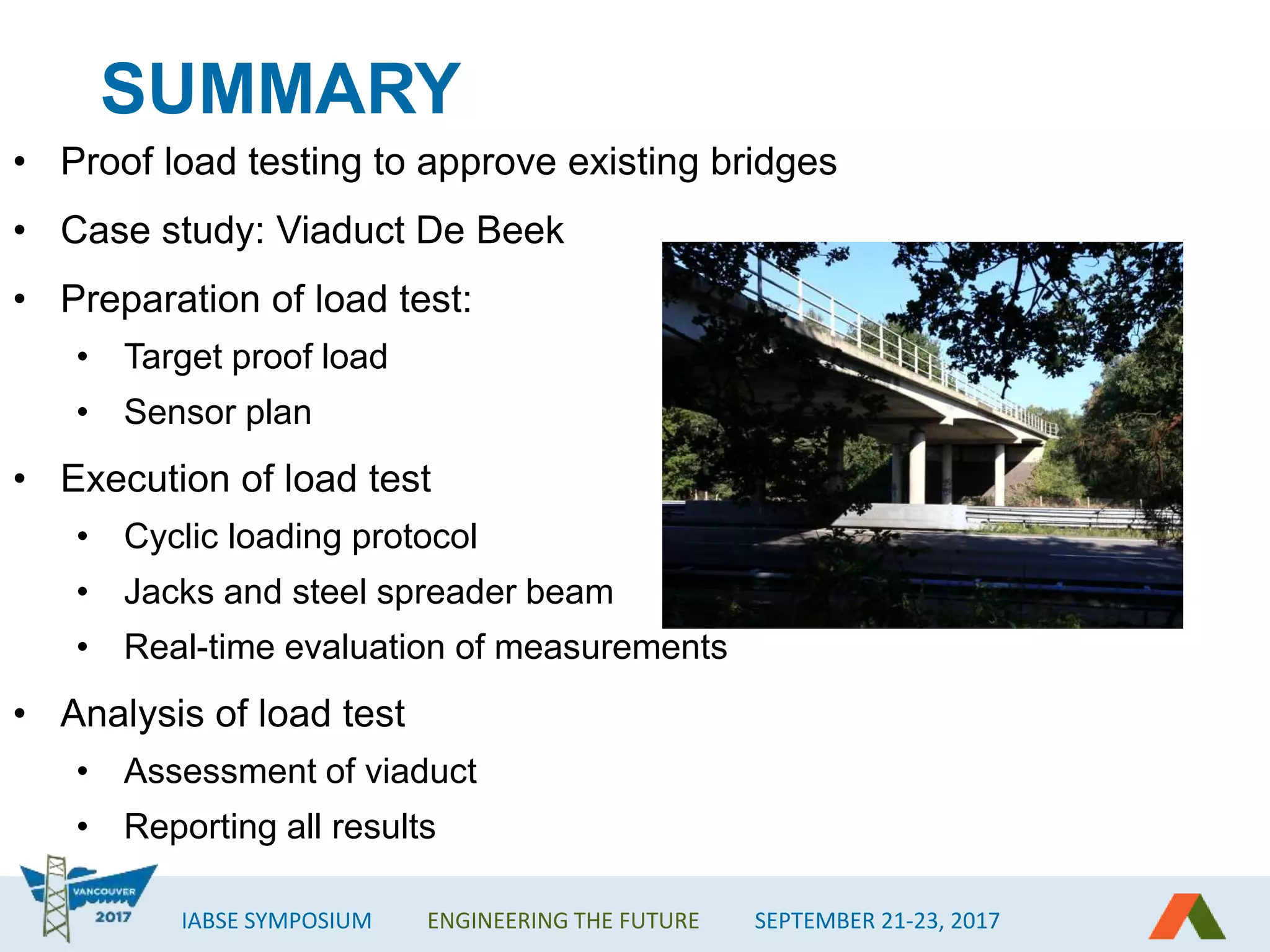


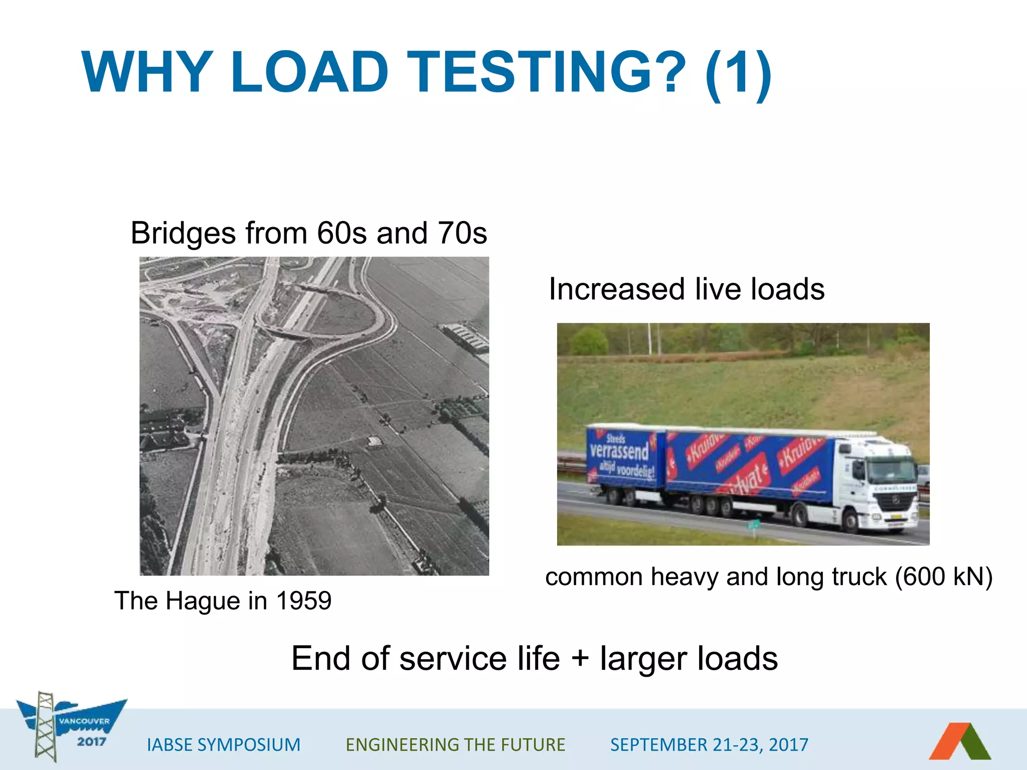
The IABSE symposium discusses the proof load testing of the viaduct de Beek, emphasizing the importance of evaluating aging bridges from the 1960s and 70s for safety under increased live loads. The document details the preparation, execution, and assessment processes of the proof load test, highlighting the use of sensors and a cyclic loading protocol. Ultimately, the viaduct demonstrated compliance with safety requirements, with recommendations for further inspections and traffic reopening.


