SlideShare a Scribd company logo
Types of Planes
• On the basis of position with respect to reference
planes
• Perpendicular to both the reference planes
• Perpendicular to one plane and parallel to the other
• Perpendicular to one plane and inclined to the other
Perpendicular planes
• Inclined to both the reference planes
Oblique planes
1
SBT
08-Jul-09
Projections of different positions
of planes
• FV and TV (both edge views) are obtained in straight line
perpendicular to x-y line
• FV  Coincide with Vertical trace (VT)
• TV  Coincide with Horizontal trace (HT)
Perpendicular to both ref. planes
VP
HP
Square
plate x y
FV
TV
2
SBT
08-Jul-09
Plane perpendicular to one plane and parallel to other
• Plane perpendicular to HP and parallel to VP
• Plane perpendicular to VP and parallel to HP
• FV shows true shape of plane
• TV shows edge view (line parallel to x-y line) of plane
A. Plane perpendicular to HP and parallel to VP
• TV shows true shape of plane
• FV shows edge view (line parallel to x-y line) of plane
B. Plane perpendicular to VP and parallel to HP
x x
y y
FV
TV
Edge view
Edge view
FV
TV
True shape
True shape
3
SBT
08-Jul-09
08-Jul-09 SBT 4
y
HP
VP
x
a
b
c
b’ c’
a’
5
10
45˚
Plane parallel to one plane and perpendicular to other plane: Illustrative Examples
Plane: equilateral triangle
Surface: parallel to HP &
perpendicular to VP
Position: corner A is 5 mm
away from VP & edge AB
makes angle of 45˚ with VP
Plane: regular pentagon
Surface: in VP
Position: edge AB
perpendicular to HP
a’
b’
c’
d’
e’
b
a e
c
d
Plane: square
Surface: parallel to VP and
10 mm from VP
Position: corner B is in HP
& edge BA & BC equally
inclined at 45˚ with HP
b’
a’ c’
d’
10
a b
d
c
45˚
08-Jul-09 SBT 5
y
HP
VP
x
Plane parallel to one plane and perpendicular to other plane: Illustrative Examples
Plane: regular hexagon
Surface: parallel to & 5
mm above HP
Position: corner F is 10 mm
from VP and edge AB & DE
are perpendicular to VP
10
f
a
b
c
d
e
5
a’
b’
f’
c’
e’
d’
Plane: regular pentagon
Surface: parallel to & 10
mm above HP
Position: corner A in VP &
edge AE makes an angle of
30˚ with VP
30˚
a
e
b
c
d
10
b’ c’ d’ e’
a’
Plane: circle of dia. 40 mm
Surface: in VP
Position: centre is 25 mm
above HP
25
1’
2’
3’
4’
1
4
3
2
Plane perpendicular to one plane and inclined to other
• A. Plane perpendicular to VP and inclined to HP
• B. Plane perpendicular to HP and inclined to VP
6
SBT
08-Jul-09
Initially plane is
resting on HP
OR llel to HP
TV1
FV1
Initially plane is
llel to VP
TV
FV FV
TV
TV
FV FV
TV
FV1
FV1
FV2
FV2
x y
x y
Reorient
previous FV
Reorient
previous TV
FV 2
TV 2
start
start end
end
7
SBT
08-Jul-09
y
HP
VP
x
Plane perpendicular to one plane and inclined to other plane: Illustrative Examples
1. A rectangle of side 20 mm and 40 mm is having shorter edge parallel to VP and
surface is perpendicular to HP inclined at angle 30˚ with VP
Initially plane is assumed to be parallel
to VP. The FV of plane is drawn first
showing true shape & size of the plane
with shorter edge is perpendicular to xy
Stage I
a’
b’ c c’
d’
a
b
d
c
In next stage plane making 30˚ with
VP. Corresponding projection is
obtained by reorienting the earlier
TV at 30˚ with xy
a
b
d
c
a’ d’
b’ c’
30˚
Then , obtain corresponding
TV i.e. edge view (line)
parallel to xy
Stage II
Then , obtain
corresponding TV which
shows an apparent shape
& size of plane
20
50
y
VP
x
Plane perpendicular to one plane and inclined to other plane: Illustrative Examples
Initially plane is assumed to be parallel
to VP. The FV of plane is drawn first
showing true shape & size of the plane
with shorter edge is perpendicular to xy
Stage I
a’
b’ c c’
d’
a
b
d
c
Then , obtain corresponding
TV i.e. edge view (line)
parallel to xy
20
50
2. A rectangle of 20 and 40 mm side is so placed that its surface is perpendicular to HP
and inclined to VP at such an angle that FV of plane appears to be a square of 20 mm
sides. Draw projection and fined out the angle of surface with VP.
Stage II
In next stage plane is
inclined to VP at such an
angle that FV appears to be
a square of 20 mm side
a’ d’
b’ c’
a
b
d
c
20
δ = 60˚
Then , obtain corresponding
TV (edge view) having same
length of earlier TV as shown
in coming step and measure
angle δ
HP
y
VP
x
Plane perpendicular to one plane and inclined to other plane: Illustrative Examples
3. A regular hexagon of 20 mm side is having as edge in VP and surface is perpendicular
to HP and makes 30˚ with VP.
HP
f’
a’
b’
c’
e’
a
b
f
c
e
d b
a
d
30˚
e
c
f
f’
a’ e’
b’
d’
d’
c’
Initially it is assumed plane is in VP. The
FV of plane is drawn first showing true
shape & size of the plane with one edge
is perpendicular to xy
Then , obtain corresponding
TV i.e. edge view (line) on
xy
In next stage plane making 30˚ with
VP. Corresponding projection is
obtained by reorienting the earlier
TV at 30˚ with xy
Then , obtain
corresponding TV which
shows an apparent shape
& size of plane
Stage I Stage II
y
VP
x
Plane perpendicular to one plane and inclined to other plane: Illustrative Examples
4. A regular hexagon of 20 mm edges is having a corner in VP and surface is
perpendicular to HP and makes 30˚ with VP.
HP
a’
b’
e’
f’
a
f
b
e
c d a 30˚
d
c
e
b
f
f’ e’
a’
d’ d’
b’
c’
c’
Initially it is assumed plane is in VP. The
FV of plane is drawn first showing true
shape & size of the plane with one edge
is parallel to xy
Then , obtain corresponding
TV i.e. edge view (line) on
xy
In next stage plane making 30˚ with
VP with a corner is on VP
Corresponding projection is
obtained by reorienting the earlier
TV at 30˚ with xy with pt ‘a’ on xy
Stage I Stage II
Then , obtain
corresponding FV which
shows an apparent shape
& size of plane
y
HP
VP
x
5. A rectangle of side 20 mm and 40 mm is having shorter edge parallel to VP and
surface is perpendicular to HP inclined at angle 30˚ with VP
Plane perpendicular to one plane and inclined to other plane: Illustrative Examples
a
b
c
d
e
108˚
a’
e’
b’
d’ c’
Stage I
Then , obtain corresponding
TV i.e. edge view (line) on
xy
a’
e’
d’
d
b’
40˚
c’
e
c
a
b
Then , obtain
corresponding TV which
shows an apparent shape
& size of plane
Initially it is assumed plane is in HP. The
TV of plane is drawn first showing true
shape & size of the plane with one edge
is perpendicular to xy
Stage II
In next stage plane making 40˚ with
HP with an edge is on HP.
Corresponding projection is
obtained by reorienting the earlier
FV at 40˚ with xy with pt a’ & e’ on
xy
y
HP
VP
x
6. A regular pentagon having a corner in HP and surface is perpendicular to VP and
inclined at 40˚ with HP.
Plane perpendicular to one plane and inclined to other plane: Illustrative Examples
b
c
d
a’
b’
e’ c’
e
d’
a
Initially it is assumed plane is in HP. The
TV of plane is drawn first showing true
shape & size of the plane with one edge is
perpendicular to xy (set farthest corner
of this edge on RHS )
Stage I
a’
e’
b’
40˚
c’
Then , obtain corresponding
TV i.e. edge view (line) on
xy
Stage II
In next stage plane making 40˚ with
HP with an edge is on HP.
Corresponding projection is
obtained by reorienting the earlier
FV at 40˚ with xy with pt a’ & e’ on
xy
e
d
d’
a
b
c
Then , obtain
corresponding TV which
shows an apparent shape
& size of plane
y
HP
VP
x
7. A circle of 40 mm diameter is having its surface perpendicular to VP and inclined at
45˚ with HP.
Plane perpendicular to one plane and inclined to other plane: Illustrative Examples
2
4
6
8
10
1’
2’ 3’ 4’ 5’ 6’
7’
8’
9’
10’
11’
12’
1’
7
7’
10’
4’
11’
12’
9’
5’
6’
8’
3’
2’
10
11 9
12 8
1 7
2 6
3 5
4
45˚
Stage I Stage II
1
3
5
12
11 9
y
HP
VP
x
8. A circle of 40 mm diameter is so placed that its surface is perpendicular to VP and is
inclined to HP such a manner that is TV appears to be an ellipse of 40 mm major axis and
30 mm minor axis. Draw the projection and find out the angle of surface of plane with HP.
Plane perpendicular to one plane and inclined to other plane: Illustrative Examples
2
4
6
8
10
1’
2’ 3’ 4’ 5’ 6’
7’
8’
9’
10’
11’
12’
1’
7
7’
10’
4’
11’
12’
9’
5’
6’
8’
3’
2’
10
11 9
12 8
1 7
2 6
3 5
4
45˚
Stage I Stage II
1
3
5
12
11 9
y
VP
x
Plane perpendicular to one plane and inclined to other plane: Illustrative Examples
3. (Q.14 Pg.21) A thin 45⁰ set square has its longest side 250 mm long in VP and
inclined at 30⁰ to HP. Its surface makes an angle of 45⁰ with VP. Draw projections.
(W-2003, 7 marks)
HP
a’
b’
45˚
a
b c
a
b
c
a’
c’
c’
b’
a’
c’
b’
a’
c’
b’
a’
c’
b’
30˚
a b
c
Initially it is assumed plane is in VP.
The FV of plane is drawn first showing
true shape & size of the plane with
longest edge is perpendicular to xy
Stage I
Then , obtain corresponding
TV i.e. edge view (line) on
xy In next stage plane making 45˚ with
VP with a longest edge is in VP.
Corresponding projection is obtained
by reorienting the earlier TV at 45˚
with xy with pt. ‘a’ & ’b’ on xy
Stage II
In last stage longest edge of plane
which is in VP making 30˚ with HP.
Corresponding projection is obtained
by reorienting the earlier FV in such a
manner that FV of the above
mentioned edge makes 30˚ with xy .
Stage III
Then , obtain
corresponding final TV .
45˚
Then , obtain
corresponding FV which
shows an apparent shape
& size of plane
x
Plane perpendicular to one plane and inclined to other plane: Illustrative Examples
3. A 30⁰ - 60⁰ triangle PQR has its longest side PR is 50 mm long and is contained in VP.
P and R are 20 mm and 45 mm respectively from HP, while point Q is 10 mm away from
VP. Draw projection. (W – 92, 7 marks)
20
VP
HP
30˚
60˚
p’
r’
p
r
q
Then , obtain corresponding
TV i.e. edge view (line) on
xy
In next stage pt. Q is 10 mm away
from VP with longest edge (PR) is in
VP. Corresponding projection is
obtained by reorienting the earlier TV
in such a manner pt. ‘q’ 10 mm below
xy
10
p
r
Initially it is assumed plane is in VP. The
FV of plane is drawn first showing true
shape & size of the plane with longest
edge PQ is perpendicular to xy and at
given position with respect to xy
Stage I
p’
q’
q’
r’
In last stage longest edge of plane
which is in VP making 30˚ with HP.
Corresponding projection is obtained
by reorienting the earlier FV in such a
manner that FV of the above
mentioned edge makes 30˚ with xy .
Stage III
Stage II
p’
q’
r’
20
r’
45
p’
q’
20
p’
Then , obtain
corresponding final TV .
r P
q
q’
y
y
x
3. A 30⁰ - 60⁰ - 90⁰ set square is having its surface making an angle of 45⁰ with HP and
is having its longer edge PQ which is 125 mm long is in HP and making an angle of 30⁰
with VP.
HP
30˚
60˚
p
r’
VP p’
q’
p’
q’
45˚
r’
p
r r
q q
p
r
q
30˚
p
r
q
p’ q’
r’
y
x
3. A thin triangular plane PQR has sides PQ 60 mm, QR = 80 mm and RP = 50
respectively. Side PQ rests on ground and makes an angle of 30⁰ with VP. Point P is 20
mm away from VP and point R is 40 mm above ground. Draw projection of plane.
p
q
r
60
p’
q’
r’
40
p’
q’
r’
r
p
q
r
p
q
20
r
p
q
30˚
r’
q’ p’
Plane perpendicular to one plane and inclined to other
• A. Plane perpendicular to VP and inclined to HP
• B. Plane perpendicular to HP and inclined to VP
• Projection is obtained in TWO stages
• In first stage, initially plane is consider to be llel to HP with given
edge condition and obtain TV (true shape) and then
corresponding FV (edge view)
• In next stage, previous FV is reoriented at given angle and
corresponding TV is obtained
A. Plane perpendicular to VP and inclined to HP
• Projection is obtained in TWO stages
• In first stage, initially plane is consider to be llel to VP with
given edge condition and obtain FV (true shape) and then
corresponding TV (edge view)
• In next stage previous TV is reoriented at given angle and
corresponding FV is obtained
B. Plane perpendicular to HP and inclined to VP
20
SBT
08-Jul-09
Plane inclined to both the plane (Oblique plane)
• A. Plane is inclined to HP with edge or dia. or diagonal is llel to HP
and inclined to VP
• B. Plane is inclined to VP with edge or dia. or diagonal is llel to VP
and inclined to HP
21
SBT
08-Jul-09
A. Plane is inclined to HP with edge or diameter
or diagonal is llel to HP and inclined to VP
TV
FV FV
TV
start
TV
FV
end
22
SBT
08-Jul-09
Initially plane is
resting on HP
OR llel to HP
FV1
FV2
x
y
Reorient
previous FV
Reorient
previous edge
FV1
TV 3
TV 2
FV 3
θ˚
φ˚
B. Plane is inclined to VP with edge or diameter
or diagonal is llel to VP and inclined to HP
FV1
x y
Initially plane is
llel to VP
Reorient
previous TV
Reorient
previous FV
TV
FV FV
TV
start
TV
FV
end
TV1
23
SBT
08-Jul-09
φ˚
θ˚
FV 2 FV3
FV3
TV2
x y
HP
VP
b’
a’
108˚
d’
c’
e’
b
a
c
e
d b
a
45
d
c
e
e’
a’
b’
c’
d’
e’
a’
b’
c’
d’
45˚
e’
b’
c’
d’
e’
b’
c’
d’
a b
e c
d
3. A pentagonal plane ABCDE of side 35 mm has its side AB in VP an inclined at 45⁰ to HP.
Draw projection when opposite corner to that edge is 45 mm in front of VP.
x y
HP
VP
a
b
c
d
e
108˚
a’
e’
b’
d’ c’
a’
e’
c’
b’
d’
a
b
c
d
e
a
b
c
d
e
a
d
e
c
b
a’ e’
b’
d’
c’
30˚
60˚
60˚
b’
c’
d’
e’
a’
y
x
3. A plate having shape of isosceles triangle has base 50 mm long and altitude 75 mm.
It is so placed that in Front View it is seen as an equilateral triangle of 50 mm sides and
one side inclined at 45⁰ to xy. Draw its Top View.
HP
VP
a
b c
a’ a’
b’
c’ c’
a
b
c
δ
a’
b’
c’
a’
b’
c’
a’
b’
c’
45˚
a b
c
b’
y
x
3. A thin rectangular plate of size 70 mm X 40 mm appears as a square of 40 mm sides
in TV with one of its sides inclined at 30⁰ to VP and parallel to HP. Draw the projections
of plate and determine its inclined with HP.
HP
VP
70
40
a
b c
d
a’
b’
d’
c’
a
b c
d
a’
b’
d’
c’
γ
30˚
b
c
d
a
40
40
b’ a’
c’ d’
y
x
3. A 30⁰ - 60⁰ set square has its shortest side 40 mm long in HP. TV of set square is an
isosceles triangle. Draw projection of plane and find its inclination with HP.
HP
VP
60˚
a
b
c
a’
b’
c’
a
b
c
a’
b’
c’
γ
y
x
3. A The TV of a 45⁰ set square with side BC in HP and side AB in VP, is a triangle abc.
The side bc = 20 mm being perpendicular to xy and angle bca = 25⁰. Draw TV and FV
and measure the inclination of set square with HP. Draw also Side View.
HP
VP
b
c
a
45˚
b
c
25˚
a
b’c’ a’ b’c’
a’
γ
x1
y1
c’’
b’’
a’’
08-Jul-09 SBT 30
x y
1
2
3
4
5
6
8
10
11
12
HP
VP 1’
2’ 3’ 4’ 5’ 6’
7’
8’
9’
10’
11’
12’
1’
7
9
7’
10’
4’
11’
12’
9’
5’
6’
8’
3’
2’
10
11 9
12 8
1 7
2 6
3 5
4
45˚
1
7
4
10
2
6
12
8
11
9
3
5
1’
2’ 12’
3’
11’
4’
10’
5’
9’
6’
8’
7’
60˚
30˚
Reorient FV1 i.e. edge view
at an angle of 45°
Reorient TV2 so that TV2 of
diagonal AB (a’b’) at an angle
of 45°
Stage I Stage II Stage III
3. A circle of 40 mm diameter is having its surface making an angle of 45⁰ with HP and end A of
diameter AB is in HP and TV of diameter AB makes an angle of 30⁰ with VP. Draw projections.
08-Jul-09 SBT 31
x y
1
2
3
4
5
6
8
10
11
12
HP
VP 1’
2’ 3’ 4’ 5’ 6’
7’
8’
9’
10’
11’
12’
1’
7
9
7’
10’
4’
11’
12’
9’
5’
6’
8’
3’
2’
10
11 9
12 8
1 7
2 6
3 5
4
45˚
30˚
a
b
b1
β˚
1
7
4
10
3
5
11
9
2
6
12
8
1’
2’ 12’
3’
4’
5’
6’
7’
8’
9’
10’
11’
Reorient FV1 i.e. edge view
at an angle of 45°
Reorient TV2 so that TV2 of
diagonal AB (a’b’) at an angle
of 45°
Stage I Stage II Stage III
3. A circle of 40 mm diameter is having its surface making an angle of 45⁰ with HP and end A of
diameter AB is in HP and diameter AB makes an angle of 30⁰ with VP. Draw projections.
08-Jul-09 SBT 32
x
y
VP
2’
4’
5’
6’
7’
7’
7’
6’
5’
4’
3’
2’
1’
7’
6’ 5’
4’
3’
2’
1’
45˚
7 1
6 2
5 3
7’
6’
5’
4’
3’
2’
1’
3’
1’
HP
1’
7’
6’
2’
5’
3’
4’
1
6
3
5’
2
4
x
y
3. A rhombus of diagonal 125 mm and 50 mm is so placed that it appears as a square of 50 mm
diagonal in TV. The smaller diagonal of rhombus is parallel to both HP and VP.
HP
VP
b
d
a’
b’
d’ c’
d
b
a
a c c
a’
b’
d
b
a c
c
a
d b
a’
d’ b’
c’
d’
c’
08-Jul-09
x
y
3. A equilateral triangle ABC having side length as 50 mm is suspended from a point O on side AB
15 mm from A in such a way that plane of triangle makes an angle of 60⁰ with VP. Point O is 50 mm
above HP and 40 mm in front of VP. Draw projection of triangle.
a’
HP b’
60˚
40
b a c
50
g’
o’
VP
c’
a’
b’
g’
o’
c’
50
a’
b’ 50
g’
o’
c’
a’
b’
g’
o’
50
c’
a
b c
o
g
b
c
o
g
a
60˚
b’
c’
a’
08-Jul-09 SBT 35
x
y
VP 2’
4’
5’
6’
7’
3’
1’
HP
3. A semicircle having diameter 100 mm is suspended from a point ‘O’ on straight edge 30 mm
from centre of that edge so that the surface makes an angle of 45⁰ with VP. Point ‘O’ is 90 mm
above HP and 50 mm in front of VP. Draw projections. (W – 05, 7 marks)
m’ g’
o’
1
7
6
2
5
3
4
m g
o
50
2’
5’
6’
7’
3’
1’
m’ g’
o’
90
2’
5’
6’
7’
3’
1’
m’
g’
o’
90
2’
5’
6’
7’
3’
1’
m’
g’
o’
30
4’
1 2 3 4 5
6
7
g
o
m
1
4
5
6
2
3
7
g
o
m
45˚
1’
2’
3’
4’
5’
6’
7’
x y
HP
VP
c
d
d
b
a
c
d
e
d
e
b
a
x y
HP
VP
a’
b’
c’
d’
e’
f’
b
a
c
f
d
e
40˚
b
a
c
f
d
e
b’ d’
c’
a’ e’
f’
b’ d’
c’
a’ e’
f’
b’
c’
a’
e’
f’
30˚
b’
c’
a’
e’
f’
a b
c
f
e d
3. A regular hexagon of 30 mm edge is having its surface inclined at 40⁰ with VP and is
having an edge in VP and inclined at an angle 30⁰ with HP. Draw projections.
x y
HP
VP
a’
b’
c’
d’
e’
f’
b
a
c
f
d
e
δ
b
a
c
f
d
e
b’ d’
c’
a’ e’
f’
b’ d’
c’
a’ e’
f’
b’
c’
a’
e’
f’
30˚
b’
c’
a’
e’
f’
a b
c
f
e d
3. One side of a regular hexagon of 30 mm side is in VP, while opposite side is 35 mm
in front of VP and inclined at 30⁰ to HP. Draw projection of plane and find its surface
inclination with VP.
35
x HP
VP
a’
b’
c’
d’
e’
f’
b
a
c
f
d
e
40˚
b
a
c
f
d
e
b’ d’
c’
a’ e’
f’
30˚
x1
y1
a
b
c
d
e
f
x y
HP
VP
c
e
f
a
f
c
e
d
b
40˚
d
f
f’ e’
b’ c’
f’ e’
a’ d’
b’ c’
f’
a’
d’
b’
c’
f’
b’
30˚
a’
d’
c’
a
f b
e c
d
b
e
c
a d a’ d’
3. A regular hexagon of 25 mm edge is having its surface making an angle of 40⁰ with
VP and is having a corner in VP. The FV of diagonal containing this corner makes an
angle of 30⁰ with HP. Draw the projections.
b a
x HP
VP
c
e
f
a b
f
c
e
d
b
40˚
a
d
f
f’ e’
b’ c’
f’ e’
a’ d’
b’ c’
30˚
b
e
c
d’ a’ d’
3. A regular hexagon of 25 mm edge is having its surface making an angle of 40⁰ with
VP and is having a corner in VP. The diagonal containing this corner makes an angle of
30⁰ with HP. Draw the projections.
d1’
d’
α
f’
e’
b’
c’
a’
a
f
b
e c
d
x y
c
e
f
a’ b’ c’
e’
d’
a d
b
a’
d’
b’
35˚
f e
a d
b c
f
e
a
d
b
c
f
a
d
b
c
e’
f’ b’
a’
x1
y1
a’’
f’’
e’’
d’’
3. A hexagonal plane ABCDEF of side30 mm has corner A in HP and opposite corner D
in VP. Draw three views o plane when diagonal AD inclined at 35⁰ to HP and parallel to
profile plane. Determine its surface inclination with VP.
e
c’ c’’
c’
e’
f’
f’
b’’
d’
x y
HP
VP
3. A thin pentagonal plate of negligible thickness and sides 25 mm long having one of
its corner in VP and surface makes an angle of 30⁰ with VP and side opposite to that
corner makes an angle of 60⁰ with HP. Draw its projection. (S – 2005)
d’
c’
108˚
a’
e’
b’
a b
e
c
d
30˚
a
c
d
b
e
e’
d’
a’
b’
c’
e’
d’
a’
b’
c’
d’
a’
b’
c’
60˚
a
b
e
c d
y
3. A composite plane consist of square ABCD of 75 mm sides and a semi circle along
CD as diameter. Draw the TV and FV of plane if its surface is perpendicular to HP and
makes an angle of 45⁰ with VP. Then draw auxiliary view on an AIP which makes an
angle of 30⁰ with edge AB which is perpendicular to HP.
6’
3’
2’
1’
5’
7’
a’
b’
4’
d’
c’
a
b
d
c
1
7
2
6
3
5
4
a
b
d
c 1
7
6
3
5
4
a’ d’
3’
4’
b’ c’ 7’
45˚
x1
b1’
7’
d1’
1’
2’
3’
4’
4’
c1’
6’
5’
6’
y1
2’
1’
a1’
x y
HP
VP
a
108˚
c
e
b’
a’
c
e
d b’
a’
5. A A thin regular pentagonal plate of 60 mm long edge has one of its edge in the HP
and perpendicular to VP, while its farthest corner is 60 mm above HP. Draw projection
of plate. Project another FV on an AVP making angle of 45⁰ with VP. Also project an
auxiliary view (ATV) of the same plane on and AIP which makes an angle of 60⁰ with HP.
60
d’
c’
e’
d
d
b b
c
e
a
x1
y1
60˚
a1
b1
e1
c1
d1
30˚
x2
y2
a1’
b1’
c1’ d1’
e1’
3. Determine a true shape of a plane where surface is perpendicular to VP and is
inclined at an angle of 45⁰ with HP and whose TV is a regular pentagon of 30 mm sides
with one side making an angle of 30⁰ with xy line in TV.
x y
HP
VP
108˚
a
c
b
d
30˚
e
a’
b’
e’
d’
c’
45˚
x2
y2
b1’
c1’
a’
d1’
e1’
3. abc is an equilateral triangle of altitude 50 mm with ab in xy and c bellow xy. abc’ is
an isosceles triangle of altitude 75 mm and c’ above xy. Determine the true shape of
triangle of ABC of which abc is TV and abc’ is FV.
x HP
VP
30˚
30˚
50
a b
c
c’
75
x1
y1
a’’
b’’
c’’
δ
γ
x2
y2
b2
a2
c2
y
3. The FV and TV of a plane is squares of 40 mm sides, with two sides equally inclined to xy.
Draw the true shape of the plane. Also determine the inclined angle between the sides.
x HP
VP
y
b’
d’
b
45˚ 45˚
c
d
x1
y1
b’’
a
c’
a’
a’’
c’’
d’’
γ
45˚ 45˚
δ
x2
y2
a2
b2
c2
d2
3. Lines AB and AC appears to make an angle of 120⁰ between them in their FV and TV line
AB is parallel to both the plane. Assume suitable view length. Determine the real angle
between lines AB and AC.
x y
HP
VP
a’
b’
c’
120˚
b
a
c
120˚
x1
y1
a’’
b’’
c’’
x2
y2
a2
b2
c2
ψ = 112⁰
x y
HP
3. The A picture frame 2 m wide and 1 mm high is to be fixed on a wall railing by two
straight wires attached to the top corner. The frame is to make an angle of 40⁰ with the
wall and the wires are to be fixed to a hook on a wall on center line of frame and 1.5 m
above railing. Find the length of wires and angles between them.
x1
y1
40˚
a’
b’ c’
d’
c’’
a’’
d’’
h’ h’’
b’’
1.5
m
a d
VP b c
2 m
h
x2
h2
a2
ψ = 91⁰
d2
y2
3. An isosceles triangle ABC is having its corners A, B and C respectively 30 mm, 60 mm and
90 mm in front of VP. Draw projection of plane and determine its surface inclination with
HP and VP. Take base of triangle AB equal to 60 mm and altitude equal to 90 mm .
x y
HP
VP
30
30
b
a
b
ci
a
b’ a’ ci’
30
c
c
x1
y1
a1’
b1’
ci1’
c1
γ = 55⁰
c’
3. An isosceles triangle ABC is having, base 60 mm and altitude 40 mm has its base AC in
HP and inclined at 30° to VP. Corner A and B are in VP. Draw its projection.
x HP
VP
Initially it is assumed ∆ ABC is in HP with pt
A is in VP and edge AC making angle of 30°
with VP. Corresponding projection is
obtained by drawing TV (showing True
Shape ) and corresponding FV (showing
Edge View)
c
30˚
bi
y
x1
y1
c’ bi’
b a
a1’
b1’
bi1’
b1’
γ = 64⁰
b’
3. An isosceles triangle PQR having base PQ 50 mm long and altitude 75 mm has its corner
P, Q and R, 25 mm, 50 mm and 75 mm respectively above ground. Draw its projection.
x HP
VP
y
ri’
r’
30
30
q’
r’
30
p’
x1
y1
q p ri
q’
p’ p1
q1
ri1
r1
γ = 55⁰
r
3. Draw TV and FV of a hexagonal lamina of 30 mm side, having two of the edges parallel to
both HP and VP and the nearest edge is 12 mm from each plane. The surface of lamina is
inclined at 60° to HP.
x y
HP
VP
c
d
e
a
12
b’
a’
c’
d’
d’
e’
b’
a’
d’
e’
d’
d
a e
d
b b d
c
60⁰
12
d
a e
b d
c
d
a
e
b
d
c
d
a
e
c
b
d
d’
d’
c’
a’ b’
x1
y1
a’’
b’’
c’’
d’’
d’’
e’’
e’
c’
Try to understand
P
Q
R
S
A
B
C
D
R
P
30
C
A
60
R C
P A
30 60
Corners P and A on the ground and
plane parallel to VP
Corners P and A on the ground and
plane perpendicular to VP with
corners R and C touches Each other
such that diagonal PR and AC
perpendicular to each other
x = 67
x2 = 302 + 602
3. An PQRS and ABCD are two square planes of diagonals 30 mm and 60 mm respectively
having their corners P and A on ground and corners R and C touches each other. The
surface of both the planes are perpendicular to each other and are perpendicular to VP.
Draw projection of planes and also find out the actual length of the side of square. (In
other words obtained the true shape of each plane.)
HP y
p’ 67 a’
r’ c’
q’
s’ b’
d’
p r
q
s
c
a
b
x1
y1
x VP
c1
b1
a1
d1
x2
y2
r1
s1
q1
p1
a e
108˚
c
b d
a
e
108˚
c
b
d
a
e
108˚
c
b
d
2. A thin 45⁰ set square has its longest side 250 mm long in VP and inclined
at 30⁰ to HP. Its surface makes an angle of 45⁰ with VP. Draw projections.
(W-2003, 7 marks)
3. A 30⁰ - 60⁰ triangle PQR has its longest side PR is 50 mm long and is
contained in VP. P and R are 20 mm and 45 mm respectively from HP, while
point Q is 10 mm away from VP. Draw projection. (W – 92, 7 marks)
a
1
2
3
4
5
6
8
10
11
12
7
9
b c
d
e
f
f
a
b
c
d
e

More Related Content

What's hot

Section of solids - ENGINEERING DRAWING/GRAPHICS
Section of solids - ENGINEERING DRAWING/GRAPHICSSection of solids - ENGINEERING DRAWING/GRAPHICS
Section of solids - ENGINEERING DRAWING/GRAPHICS
Abhishek Kandare
 
Projection of planes 020
Projection of planes 020Projection of planes 020
Projection of planes 020Akash Sood
 
Projection of Solids
Projection of SolidsProjection of Solids
Projection of Solids
ANIKET SURYAWANSHI
 
Projection of solids - ENGINEERING DRAWING/GRAPHICS
Projection of solids - ENGINEERING DRAWING/GRAPHICSProjection of solids - ENGINEERING DRAWING/GRAPHICS
Projection of solids - ENGINEERING DRAWING/GRAPHICS
Abhishek Kandare
 
Projection of planes
Projection of planesProjection of planes
Projection of planes
Smit Parikh
 
Projection of solids
Projection of solidsProjection of solids
Projection of solidsSumit Chandak
 
Projection of Planes
Projection of PlanesProjection of Planes
Projection of PlanesNilesh Jakher
 
EG UNIT-II PROJECTION OF PLANES.ppt
EG UNIT-II PROJECTION OF PLANES.pptEG UNIT-II PROJECTION OF PLANES.ppt
EG UNIT-II PROJECTION OF PLANES.ppt
Ganesamoorthy14
 
Projection of planes
Projection of planesProjection of planes
Projection of planes
Kashyap Shah
 
Engineering Graphics-Lines
Engineering Graphics-LinesEngineering Graphics-Lines
Engineering Graphics-Lines
Dr. Ramesh B
 
Projection of lines
Projection of linesProjection of lines
Projection of lines
Kashyap Shah
 
Projection of Planes- Engineering Graphics
Projection of Planes- Engineering GraphicsProjection of Planes- Engineering Graphics
Projection of Planes- Engineering Graphics
Dr Ramesh B T
 
Projectionofpointsandlines (1)
Projectionofpointsandlines (1)Projectionofpointsandlines (1)
Projectionofpointsandlines (1)
MSTAMIL21
 
B.tech i eg u2 loci of point and projection of point and line
B.tech  i eg u2 loci of point and projection of point and lineB.tech  i eg u2 loci of point and projection of point and line
B.tech i eg u2 loci of point and projection of point and line
Rai University
 
Typical problem
Typical problemTypical problem
Typical problemDeepa Rani
 
Development of surfaces of solids
Development of surfaces of solidsDevelopment of surfaces of solids
Development of surfaces of solids
Kashyap Shah
 
Projection of planes 029
Projection of planes 029Projection of planes 029
Projection of planes 029Akash Sood
 
Unit ii projection of planes
Unit  ii projection of planesUnit  ii projection of planes
Unit ii projection of planes
ganesasmoorthy raju
 

What's hot (20)

Section of solids - ENGINEERING DRAWING/GRAPHICS
Section of solids - ENGINEERING DRAWING/GRAPHICSSection of solids - ENGINEERING DRAWING/GRAPHICS
Section of solids - ENGINEERING DRAWING/GRAPHICS
 
Projection of planes 020
Projection of planes 020Projection of planes 020
Projection of planes 020
 
Projection of Solids
Projection of SolidsProjection of Solids
Projection of Solids
 
Projection of solids - ENGINEERING DRAWING/GRAPHICS
Projection of solids - ENGINEERING DRAWING/GRAPHICSProjection of solids - ENGINEERING DRAWING/GRAPHICS
Projection of solids - ENGINEERING DRAWING/GRAPHICS
 
Projection of planes
Projection of planesProjection of planes
Projection of planes
 
Projection of solids
Projection of solidsProjection of solids
Projection of solids
 
Projection of Planes
Projection of PlanesProjection of Planes
Projection of Planes
 
EG UNIT-II PROJECTION OF PLANES.ppt
EG UNIT-II PROJECTION OF PLANES.pptEG UNIT-II PROJECTION OF PLANES.ppt
EG UNIT-II PROJECTION OF PLANES.ppt
 
Projection of planes
Projection of planesProjection of planes
Projection of planes
 
Engineering Graphics-Lines
Engineering Graphics-LinesEngineering Graphics-Lines
Engineering Graphics-Lines
 
Projection of lines
Projection of linesProjection of lines
Projection of lines
 
Projection of Planes- Engineering Graphics
Projection of Planes- Engineering GraphicsProjection of Planes- Engineering Graphics
Projection of Planes- Engineering Graphics
 
Projectionofpointsandlines (1)
Projectionofpointsandlines (1)Projectionofpointsandlines (1)
Projectionofpointsandlines (1)
 
B.tech i eg u2 loci of point and projection of point and line
B.tech  i eg u2 loci of point and projection of point and lineB.tech  i eg u2 loci of point and projection of point and line
B.tech i eg u2 loci of point and projection of point and line
 
Typical problem
Typical problemTypical problem
Typical problem
 
Section of solids
Section of solidsSection of solids
Section of solids
 
Section of solids
Section of solidsSection of solids
Section of solids
 
Development of surfaces of solids
Development of surfaces of solidsDevelopment of surfaces of solids
Development of surfaces of solids
 
Projection of planes 029
Projection of planes 029Projection of planes 029
Projection of planes 029
 
Unit ii projection of planes
Unit  ii projection of planesUnit  ii projection of planes
Unit ii projection of planes
 

Similar to Projections of planes.pptx

Eg projection of plane
Eg projection of planeEg projection of plane
Eg projection of plane
Ravi Patel
 
Projection of Plane-engineering drawing
Projection of Plane-engineering drawingProjection of Plane-engineering drawing
Projection of Plane-engineering drawing
Mohd Mujahid Nasir
 
projection of Plane
projection of Planeprojection of Plane
projection of Plane
Mohd Mujahid Nasir
 
7. projection of solids
7. projection of solids7. projection of solids
7. projection of solids
gvjha3
 
7. projection of solids
7. projection of solids7. projection of solids
7. projection of solids
kgauthami2014
 
Projectionofplanes 120504111700-phpapp01
Projectionofplanes 120504111700-phpapp01Projectionofplanes 120504111700-phpapp01
Projectionofplanes 120504111700-phpapp01
Sahid Parvez
 
Projection of planes
Projection of planesProjection of planes
Projection of planesgtuautonomous
 
projectionn of planes
projectionn of planesprojectionn of planes
Ist Year Engineering Graphics E D For B E Students (1) (1)
Ist Year  Engineering  Graphics  E D For  B E  Students (1) (1)Ist Year  Engineering  Graphics  E D For  B E  Students (1) (1)
Ist Year Engineering Graphics E D For B E Students (1) (1)Vivek Sricharan
 
Ist year engineering-graphics-ed-for-be-students (1) (1)
Ist year engineering-graphics-ed-for-be-students (1) (1)Ist year engineering-graphics-ed-for-be-students (1) (1)
Ist year engineering-graphics-ed-for-be-students (1) (1)
Vivek Sricharan
 
Ist Year Engineering Graphics E D For B E Students (1) (1)
Ist Year  Engineering  Graphics  E D For  B E  Students (1) (1)Ist Year  Engineering  Graphics  E D For  B E  Students (1) (1)
Ist Year Engineering Graphics E D For B E Students (1) (1)Vivek Sricharan
 
Demo_ED.ppt.pptx
Demo_ED.ppt.pptxDemo_ED.ppt.pptx
Demo_ED.ppt.pptx
Praveen Kumar
 
Projections of planes
Projections of planesProjections of planes
Projections of planes
Hemin Patel
 
Projection of planes
Projection of planesProjection of planes
Projection of planesSumit Chandak
 
Projection of straight lines I.pdf
Projection of straight lines I.pdfProjection of straight lines I.pdf
Projection of straight lines I.pdf
MuditKumar59
 
Unit 1 Projection of straight lines I.pdf
Unit 1 Projection of straight lines I.pdfUnit 1 Projection of straight lines I.pdf
Unit 1 Projection of straight lines I.pdf
Nilesh Kalyankar
 
6 projections of lines, points, planes
6 projections of lines, points, planes6 projections of lines, points, planes
6 projections of lines, points, planes
Ravi Patel
 
Projection of planes
Projection of planesProjection of planes
Projection of planesAbhay Jain
 
Engineering Drawing Notes For 1st and 2nd sem (Engineering)
Engineering Drawing Notes For 1st and 2nd sem (Engineering)Engineering Drawing Notes For 1st and 2nd sem (Engineering)
Engineering Drawing Notes For 1st and 2nd sem (Engineering)
Saroj Kumar
 

Similar to Projections of planes.pptx (20)

Eg projection of plane
Eg projection of planeEg projection of plane
Eg projection of plane
 
Projection of Plane-engineering drawing
Projection of Plane-engineering drawingProjection of Plane-engineering drawing
Projection of Plane-engineering drawing
 
projection of Plane
projection of Planeprojection of Plane
projection of Plane
 
7. projection of solids
7. projection of solids7. projection of solids
7. projection of solids
 
7. projection of solids
7. projection of solids7. projection of solids
7. projection of solids
 
Projectionofplanes 120504111700-phpapp01
Projectionofplanes 120504111700-phpapp01Projectionofplanes 120504111700-phpapp01
Projectionofplanes 120504111700-phpapp01
 
Projection of planes
Projection of planesProjection of planes
Projection of planes
 
projectionn of planes
projectionn of planesprojectionn of planes
projectionn of planes
 
Ist Year Engineering Graphics E D For B E Students (1) (1)
Ist Year  Engineering  Graphics  E D For  B E  Students (1) (1)Ist Year  Engineering  Graphics  E D For  B E  Students (1) (1)
Ist Year Engineering Graphics E D For B E Students (1) (1)
 
Ist year engineering-graphics-ed-for-be-students (1) (1)
Ist year engineering-graphics-ed-for-be-students (1) (1)Ist year engineering-graphics-ed-for-be-students (1) (1)
Ist year engineering-graphics-ed-for-be-students (1) (1)
 
Ist Year Engineering Graphics E D For B E Students (1) (1)
Ist Year  Engineering  Graphics  E D For  B E  Students (1) (1)Ist Year  Engineering  Graphics  E D For  B E  Students (1) (1)
Ist Year Engineering Graphics E D For B E Students (1) (1)
 
Demo_ED.ppt.pptx
Demo_ED.ppt.pptxDemo_ED.ppt.pptx
Demo_ED.ppt.pptx
 
Projection of planes
Projection of planesProjection of planes
Projection of planes
 
Projections of planes
Projections of planesProjections of planes
Projections of planes
 
Projection of planes
Projection of planesProjection of planes
Projection of planes
 
Projection of straight lines I.pdf
Projection of straight lines I.pdfProjection of straight lines I.pdf
Projection of straight lines I.pdf
 
Unit 1 Projection of straight lines I.pdf
Unit 1 Projection of straight lines I.pdfUnit 1 Projection of straight lines I.pdf
Unit 1 Projection of straight lines I.pdf
 
6 projections of lines, points, planes
6 projections of lines, points, planes6 projections of lines, points, planes
6 projections of lines, points, planes
 
Projection of planes
Projection of planesProjection of planes
Projection of planes
 
Engineering Drawing Notes For 1st and 2nd sem (Engineering)
Engineering Drawing Notes For 1st and 2nd sem (Engineering)Engineering Drawing Notes For 1st and 2nd sem (Engineering)
Engineering Drawing Notes For 1st and 2nd sem (Engineering)
 

More from Praveen Kumar

UNIT 5-Special Welding process mechanical.ppt
UNIT 5-Special Welding process mechanical.pptUNIT 5-Special Welding process mechanical.ppt
UNIT 5-Special Welding process mechanical.ppt
Praveen Kumar
 
1-introductionOPERARION RESEARCH TECHNIQUES.ppt
1-introductionOPERARION RESEARCH TECHNIQUES.ppt1-introductionOPERARION RESEARCH TECHNIQUES.ppt
1-introductionOPERARION RESEARCH TECHNIQUES.ppt
Praveen Kumar
 
Unit-II Basic Mechanical Engineering.pptx
Unit-II Basic Mechanical Engineering.pptxUnit-II Basic Mechanical Engineering.pptx
Unit-II Basic Mechanical Engineering.pptx
Praveen Kumar
 
UNIT 5-Special Welding processwelding.ppt
UNIT 5-Special Welding processwelding.pptUNIT 5-Special Welding processwelding.ppt
UNIT 5-Special Welding processwelding.ppt
Praveen Kumar
 
UNIT 5-Special Welding processmechanical welding.ppt
UNIT 5-Special Welding processmechanical welding.pptUNIT 5-Special Welding processmechanical welding.ppt
UNIT 5-Special Welding processmechanical welding.ppt
Praveen Kumar
 
UNIT4-Welding processmechanical welding.ppt
UNIT4-Welding processmechanical welding.pptUNIT4-Welding processmechanical welding.ppt
UNIT4-Welding processmechanical welding.ppt
Praveen Kumar
 
GATE Preparationmecgacnialengineeing.pptx
GATE Preparationmecgacnialengineeing.pptxGATE Preparationmecgacnialengineeing.pptx
GATE Preparationmecgacnialengineeing.pptx
Praveen Kumar
 
UNIT4-Welding process MECHANICALWELDING.ppt
UNIT4-Welding process MECHANICALWELDING.pptUNIT4-Welding process MECHANICALWELDING.ppt
UNIT4-Welding process MECHANICALWELDING.ppt
Praveen Kumar
 
UNIT4-Welding processmechanicalweding .ppt
UNIT4-Welding processmechanicalweding .pptUNIT4-Welding processmechanicalweding .ppt
UNIT4-Welding processmechanicalweding .ppt
Praveen Kumar
 
UNIT4-Welding processcastingprocessdefects.ppt
UNIT4-Welding processcastingprocessdefects.pptUNIT4-Welding processcastingprocessdefects.ppt
UNIT4-Welding processcastingprocessdefects.ppt
Praveen Kumar
 
UNIT4-Welding processcastingweldingdefect.ppt
UNIT4-Welding processcastingweldingdefect.pptUNIT4-Welding processcastingweldingdefect.ppt
UNIT4-Welding processcastingweldingdefect.ppt
Praveen Kumar
 
UNIT3-Special casting processmechanical.ppt
UNIT3-Special casting processmechanical.pptUNIT3-Special casting processmechanical.ppt
UNIT3-Special casting processmechanical.ppt
Praveen Kumar
 
UNIT3-Special casting processcasting.ppt
UNIT3-Special casting processcasting.pptUNIT3-Special casting processcasting.ppt
UNIT3-Special casting processcasting.ppt
Praveen Kumar
 
Unit-II Basic Mechanical Engineering.pptx
Unit-II Basic Mechanical Engineering.pptxUnit-II Basic Mechanical Engineering.pptx
Unit-II Basic Mechanical Engineering.pptx
Praveen Kumar
 
UNIT3-Special casting processmechanica.ppt
UNIT3-Special casting processmechanica.pptUNIT3-Special casting processmechanica.ppt
UNIT3-Special casting processmechanica.ppt
Praveen Kumar
 
UNIT3-Special casting processmechanical.ppt
UNIT3-Special casting processmechanical.pptUNIT3-Special casting processmechanical.ppt
UNIT3-Special casting processmechanical.ppt
Praveen Kumar
 
Unit-I Basic Mechanical Engineering.pptx
Unit-I Basic Mechanical Engineering.pptxUnit-I Basic Mechanical Engineering.pptx
Unit-I Basic Mechanical Engineering.pptx
Praveen Kumar
 
UNIT3-Special casting process mechanical.ppt
UNIT3-Special casting process mechanical.pptUNIT3-Special casting process mechanical.ppt
UNIT3-Special casting process mechanical.ppt
Praveen Kumar
 
UNIT1-CastingprocessPROCESSINTRODUCTION.ppt
UNIT1-CastingprocessPROCESSINTRODUCTION.pptUNIT1-CastingprocessPROCESSINTRODUCTION.ppt
UNIT1-CastingprocessPROCESSINTRODUCTION.ppt
Praveen Kumar
 
Basic Mechanical Engineeringrole of mechanical engineering society-MID-I - Co...
Basic Mechanical Engineeringrole of mechanical engineering society-MID-I - Co...Basic Mechanical Engineeringrole of mechanical engineering society-MID-I - Co...
Basic Mechanical Engineeringrole of mechanical engineering society-MID-I - Co...
Praveen Kumar
 

More from Praveen Kumar (20)

UNIT 5-Special Welding process mechanical.ppt
UNIT 5-Special Welding process mechanical.pptUNIT 5-Special Welding process mechanical.ppt
UNIT 5-Special Welding process mechanical.ppt
 
1-introductionOPERARION RESEARCH TECHNIQUES.ppt
1-introductionOPERARION RESEARCH TECHNIQUES.ppt1-introductionOPERARION RESEARCH TECHNIQUES.ppt
1-introductionOPERARION RESEARCH TECHNIQUES.ppt
 
Unit-II Basic Mechanical Engineering.pptx
Unit-II Basic Mechanical Engineering.pptxUnit-II Basic Mechanical Engineering.pptx
Unit-II Basic Mechanical Engineering.pptx
 
UNIT 5-Special Welding processwelding.ppt
UNIT 5-Special Welding processwelding.pptUNIT 5-Special Welding processwelding.ppt
UNIT 5-Special Welding processwelding.ppt
 
UNIT 5-Special Welding processmechanical welding.ppt
UNIT 5-Special Welding processmechanical welding.pptUNIT 5-Special Welding processmechanical welding.ppt
UNIT 5-Special Welding processmechanical welding.ppt
 
UNIT4-Welding processmechanical welding.ppt
UNIT4-Welding processmechanical welding.pptUNIT4-Welding processmechanical welding.ppt
UNIT4-Welding processmechanical welding.ppt
 
GATE Preparationmecgacnialengineeing.pptx
GATE Preparationmecgacnialengineeing.pptxGATE Preparationmecgacnialengineeing.pptx
GATE Preparationmecgacnialengineeing.pptx
 
UNIT4-Welding process MECHANICALWELDING.ppt
UNIT4-Welding process MECHANICALWELDING.pptUNIT4-Welding process MECHANICALWELDING.ppt
UNIT4-Welding process MECHANICALWELDING.ppt
 
UNIT4-Welding processmechanicalweding .ppt
UNIT4-Welding processmechanicalweding .pptUNIT4-Welding processmechanicalweding .ppt
UNIT4-Welding processmechanicalweding .ppt
 
UNIT4-Welding processcastingprocessdefects.ppt
UNIT4-Welding processcastingprocessdefects.pptUNIT4-Welding processcastingprocessdefects.ppt
UNIT4-Welding processcastingprocessdefects.ppt
 
UNIT4-Welding processcastingweldingdefect.ppt
UNIT4-Welding processcastingweldingdefect.pptUNIT4-Welding processcastingweldingdefect.ppt
UNIT4-Welding processcastingweldingdefect.ppt
 
UNIT3-Special casting processmechanical.ppt
UNIT3-Special casting processmechanical.pptUNIT3-Special casting processmechanical.ppt
UNIT3-Special casting processmechanical.ppt
 
UNIT3-Special casting processcasting.ppt
UNIT3-Special casting processcasting.pptUNIT3-Special casting processcasting.ppt
UNIT3-Special casting processcasting.ppt
 
Unit-II Basic Mechanical Engineering.pptx
Unit-II Basic Mechanical Engineering.pptxUnit-II Basic Mechanical Engineering.pptx
Unit-II Basic Mechanical Engineering.pptx
 
UNIT3-Special casting processmechanica.ppt
UNIT3-Special casting processmechanica.pptUNIT3-Special casting processmechanica.ppt
UNIT3-Special casting processmechanica.ppt
 
UNIT3-Special casting processmechanical.ppt
UNIT3-Special casting processmechanical.pptUNIT3-Special casting processmechanical.ppt
UNIT3-Special casting processmechanical.ppt
 
Unit-I Basic Mechanical Engineering.pptx
Unit-I Basic Mechanical Engineering.pptxUnit-I Basic Mechanical Engineering.pptx
Unit-I Basic Mechanical Engineering.pptx
 
UNIT3-Special casting process mechanical.ppt
UNIT3-Special casting process mechanical.pptUNIT3-Special casting process mechanical.ppt
UNIT3-Special casting process mechanical.ppt
 
UNIT1-CastingprocessPROCESSINTRODUCTION.ppt
UNIT1-CastingprocessPROCESSINTRODUCTION.pptUNIT1-CastingprocessPROCESSINTRODUCTION.ppt
UNIT1-CastingprocessPROCESSINTRODUCTION.ppt
 
Basic Mechanical Engineeringrole of mechanical engineering society-MID-I - Co...
Basic Mechanical Engineeringrole of mechanical engineering society-MID-I - Co...Basic Mechanical Engineeringrole of mechanical engineering society-MID-I - Co...
Basic Mechanical Engineeringrole of mechanical engineering society-MID-I - Co...
 

Recently uploaded

Gen AI Study Jams _ For the GDSC Leads in India.pdf
Gen AI Study Jams _ For the GDSC Leads in India.pdfGen AI Study Jams _ For the GDSC Leads in India.pdf
Gen AI Study Jams _ For the GDSC Leads in India.pdf
gdsczhcet
 
Investor-Presentation-Q1FY2024 investor presentation document.pptx
Investor-Presentation-Q1FY2024 investor presentation document.pptxInvestor-Presentation-Q1FY2024 investor presentation document.pptx
Investor-Presentation-Q1FY2024 investor presentation document.pptx
AmarGB2
 
在线办理(ANU毕业证书)澳洲国立大学毕业证录取通知书一模一样
在线办理(ANU毕业证书)澳洲国立大学毕业证录取通知书一模一样在线办理(ANU毕业证书)澳洲国立大学毕业证录取通知书一模一样
在线办理(ANU毕业证书)澳洲国立大学毕业证录取通知书一模一样
obonagu
 
Heap Sort (SS).ppt FOR ENGINEERING GRADUATES, BCA, MCA, MTECH, BSC STUDENTS
Heap Sort (SS).ppt FOR ENGINEERING GRADUATES, BCA, MCA, MTECH, BSC STUDENTSHeap Sort (SS).ppt FOR ENGINEERING GRADUATES, BCA, MCA, MTECH, BSC STUDENTS
Heap Sort (SS).ppt FOR ENGINEERING GRADUATES, BCA, MCA, MTECH, BSC STUDENTS
Soumen Santra
 
RAT: Retrieval Augmented Thoughts Elicit Context-Aware Reasoning in Long-Hori...
RAT: Retrieval Augmented Thoughts Elicit Context-Aware Reasoning in Long-Hori...RAT: Retrieval Augmented Thoughts Elicit Context-Aware Reasoning in Long-Hori...
RAT: Retrieval Augmented Thoughts Elicit Context-Aware Reasoning in Long-Hori...
thanhdowork
 
Steel & Timber Design according to British Standard
Steel & Timber Design according to British StandardSteel & Timber Design according to British Standard
Steel & Timber Design according to British Standard
AkolbilaEmmanuel1
 
NUMERICAL SIMULATIONS OF HEAT AND MASS TRANSFER IN CONDENSING HEAT EXCHANGERS...
NUMERICAL SIMULATIONS OF HEAT AND MASS TRANSFER IN CONDENSING HEAT EXCHANGERS...NUMERICAL SIMULATIONS OF HEAT AND MASS TRANSFER IN CONDENSING HEAT EXCHANGERS...
NUMERICAL SIMULATIONS OF HEAT AND MASS TRANSFER IN CONDENSING HEAT EXCHANGERS...
ssuser7dcef0
 
road safety engineering r s e unit 3.pdf
road safety engineering  r s e unit 3.pdfroad safety engineering  r s e unit 3.pdf
road safety engineering r s e unit 3.pdf
VENKATESHvenky89705
 
DfMAy 2024 - key insights and contributions
DfMAy 2024 - key insights and contributionsDfMAy 2024 - key insights and contributions
DfMAy 2024 - key insights and contributions
gestioneergodomus
 
Cosmetic shop management system project report.pdf
Cosmetic shop management system project report.pdfCosmetic shop management system project report.pdf
Cosmetic shop management system project report.pdf
Kamal Acharya
 
Understanding Inductive Bias in Machine Learning
Understanding Inductive Bias in Machine LearningUnderstanding Inductive Bias in Machine Learning
Understanding Inductive Bias in Machine Learning
SUTEJAS
 
Hybrid optimization of pumped hydro system and solar- Engr. Abdul-Azeez.pdf
Hybrid optimization of pumped hydro system and solar- Engr. Abdul-Azeez.pdfHybrid optimization of pumped hydro system and solar- Engr. Abdul-Azeez.pdf
Hybrid optimization of pumped hydro system and solar- Engr. Abdul-Azeez.pdf
fxintegritypublishin
 
Final project report on grocery store management system..pdf
Final project report on grocery store management system..pdfFinal project report on grocery store management system..pdf
Final project report on grocery store management system..pdf
Kamal Acharya
 
PPT on GRP pipes manufacturing and testing
PPT on GRP pipes manufacturing and testingPPT on GRP pipes manufacturing and testing
PPT on GRP pipes manufacturing and testing
anoopmanoharan2
 
Basic Industrial Engineering terms for apparel
Basic Industrial Engineering terms for apparelBasic Industrial Engineering terms for apparel
Basic Industrial Engineering terms for apparel
top1002
 
一比一原版(UofT毕业证)多伦多大学毕业证成绩单如何办理
一比一原版(UofT毕业证)多伦多大学毕业证成绩单如何办理一比一原版(UofT毕业证)多伦多大学毕业证成绩单如何办理
一比一原版(UofT毕业证)多伦多大学毕业证成绩单如何办理
ydteq
 
CW RADAR, FMCW RADAR, FMCW ALTIMETER, AND THEIR PARAMETERS
CW RADAR, FMCW RADAR, FMCW ALTIMETER, AND THEIR PARAMETERSCW RADAR, FMCW RADAR, FMCW ALTIMETER, AND THEIR PARAMETERS
CW RADAR, FMCW RADAR, FMCW ALTIMETER, AND THEIR PARAMETERS
veerababupersonal22
 
Sachpazis:Terzaghi Bearing Capacity Estimation in simple terms with Calculati...
Sachpazis:Terzaghi Bearing Capacity Estimation in simple terms with Calculati...Sachpazis:Terzaghi Bearing Capacity Estimation in simple terms with Calculati...
Sachpazis:Terzaghi Bearing Capacity Estimation in simple terms with Calculati...
Dr.Costas Sachpazis
 
MCQ Soil mechanics questions (Soil shear strength).pdf
MCQ Soil mechanics questions (Soil shear strength).pdfMCQ Soil mechanics questions (Soil shear strength).pdf
MCQ Soil mechanics questions (Soil shear strength).pdf
Osamah Alsalih
 
DESIGN AND ANALYSIS OF A CAR SHOWROOM USING E TABS
DESIGN AND ANALYSIS OF A CAR SHOWROOM USING E TABSDESIGN AND ANALYSIS OF A CAR SHOWROOM USING E TABS
DESIGN AND ANALYSIS OF A CAR SHOWROOM USING E TABS
itech2017
 

Recently uploaded (20)

Gen AI Study Jams _ For the GDSC Leads in India.pdf
Gen AI Study Jams _ For the GDSC Leads in India.pdfGen AI Study Jams _ For the GDSC Leads in India.pdf
Gen AI Study Jams _ For the GDSC Leads in India.pdf
 
Investor-Presentation-Q1FY2024 investor presentation document.pptx
Investor-Presentation-Q1FY2024 investor presentation document.pptxInvestor-Presentation-Q1FY2024 investor presentation document.pptx
Investor-Presentation-Q1FY2024 investor presentation document.pptx
 
在线办理(ANU毕业证书)澳洲国立大学毕业证录取通知书一模一样
在线办理(ANU毕业证书)澳洲国立大学毕业证录取通知书一模一样在线办理(ANU毕业证书)澳洲国立大学毕业证录取通知书一模一样
在线办理(ANU毕业证书)澳洲国立大学毕业证录取通知书一模一样
 
Heap Sort (SS).ppt FOR ENGINEERING GRADUATES, BCA, MCA, MTECH, BSC STUDENTS
Heap Sort (SS).ppt FOR ENGINEERING GRADUATES, BCA, MCA, MTECH, BSC STUDENTSHeap Sort (SS).ppt FOR ENGINEERING GRADUATES, BCA, MCA, MTECH, BSC STUDENTS
Heap Sort (SS).ppt FOR ENGINEERING GRADUATES, BCA, MCA, MTECH, BSC STUDENTS
 
RAT: Retrieval Augmented Thoughts Elicit Context-Aware Reasoning in Long-Hori...
RAT: Retrieval Augmented Thoughts Elicit Context-Aware Reasoning in Long-Hori...RAT: Retrieval Augmented Thoughts Elicit Context-Aware Reasoning in Long-Hori...
RAT: Retrieval Augmented Thoughts Elicit Context-Aware Reasoning in Long-Hori...
 
Steel & Timber Design according to British Standard
Steel & Timber Design according to British StandardSteel & Timber Design according to British Standard
Steel & Timber Design according to British Standard
 
NUMERICAL SIMULATIONS OF HEAT AND MASS TRANSFER IN CONDENSING HEAT EXCHANGERS...
NUMERICAL SIMULATIONS OF HEAT AND MASS TRANSFER IN CONDENSING HEAT EXCHANGERS...NUMERICAL SIMULATIONS OF HEAT AND MASS TRANSFER IN CONDENSING HEAT EXCHANGERS...
NUMERICAL SIMULATIONS OF HEAT AND MASS TRANSFER IN CONDENSING HEAT EXCHANGERS...
 
road safety engineering r s e unit 3.pdf
road safety engineering  r s e unit 3.pdfroad safety engineering  r s e unit 3.pdf
road safety engineering r s e unit 3.pdf
 
DfMAy 2024 - key insights and contributions
DfMAy 2024 - key insights and contributionsDfMAy 2024 - key insights and contributions
DfMAy 2024 - key insights and contributions
 
Cosmetic shop management system project report.pdf
Cosmetic shop management system project report.pdfCosmetic shop management system project report.pdf
Cosmetic shop management system project report.pdf
 
Understanding Inductive Bias in Machine Learning
Understanding Inductive Bias in Machine LearningUnderstanding Inductive Bias in Machine Learning
Understanding Inductive Bias in Machine Learning
 
Hybrid optimization of pumped hydro system and solar- Engr. Abdul-Azeez.pdf
Hybrid optimization of pumped hydro system and solar- Engr. Abdul-Azeez.pdfHybrid optimization of pumped hydro system and solar- Engr. Abdul-Azeez.pdf
Hybrid optimization of pumped hydro system and solar- Engr. Abdul-Azeez.pdf
 
Final project report on grocery store management system..pdf
Final project report on grocery store management system..pdfFinal project report on grocery store management system..pdf
Final project report on grocery store management system..pdf
 
PPT on GRP pipes manufacturing and testing
PPT on GRP pipes manufacturing and testingPPT on GRP pipes manufacturing and testing
PPT on GRP pipes manufacturing and testing
 
Basic Industrial Engineering terms for apparel
Basic Industrial Engineering terms for apparelBasic Industrial Engineering terms for apparel
Basic Industrial Engineering terms for apparel
 
一比一原版(UofT毕业证)多伦多大学毕业证成绩单如何办理
一比一原版(UofT毕业证)多伦多大学毕业证成绩单如何办理一比一原版(UofT毕业证)多伦多大学毕业证成绩单如何办理
一比一原版(UofT毕业证)多伦多大学毕业证成绩单如何办理
 
CW RADAR, FMCW RADAR, FMCW ALTIMETER, AND THEIR PARAMETERS
CW RADAR, FMCW RADAR, FMCW ALTIMETER, AND THEIR PARAMETERSCW RADAR, FMCW RADAR, FMCW ALTIMETER, AND THEIR PARAMETERS
CW RADAR, FMCW RADAR, FMCW ALTIMETER, AND THEIR PARAMETERS
 
Sachpazis:Terzaghi Bearing Capacity Estimation in simple terms with Calculati...
Sachpazis:Terzaghi Bearing Capacity Estimation in simple terms with Calculati...Sachpazis:Terzaghi Bearing Capacity Estimation in simple terms with Calculati...
Sachpazis:Terzaghi Bearing Capacity Estimation in simple terms with Calculati...
 
MCQ Soil mechanics questions (Soil shear strength).pdf
MCQ Soil mechanics questions (Soil shear strength).pdfMCQ Soil mechanics questions (Soil shear strength).pdf
MCQ Soil mechanics questions (Soil shear strength).pdf
 
DESIGN AND ANALYSIS OF A CAR SHOWROOM USING E TABS
DESIGN AND ANALYSIS OF A CAR SHOWROOM USING E TABSDESIGN AND ANALYSIS OF A CAR SHOWROOM USING E TABS
DESIGN AND ANALYSIS OF A CAR SHOWROOM USING E TABS
 

Projections of planes.pptx

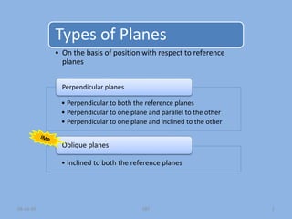
  • 1. Types of Planes • On the basis of position with respect to reference planes • Perpendicular to both the reference planes • Perpendicular to one plane and parallel to the other • Perpendicular to one plane and inclined to the other Perpendicular planes • Inclined to both the reference planes Oblique planes 1 SBT 08-Jul-09
  • 2. Projections of different positions of planes • FV and TV (both edge views) are obtained in straight line perpendicular to x-y line • FV  Coincide with Vertical trace (VT) • TV  Coincide with Horizontal trace (HT) Perpendicular to both ref. planes VP HP Square plate x y FV TV 2 SBT 08-Jul-09
  • 3. Plane perpendicular to one plane and parallel to other • Plane perpendicular to HP and parallel to VP • Plane perpendicular to VP and parallel to HP • FV shows true shape of plane • TV shows edge view (line parallel to x-y line) of plane A. Plane perpendicular to HP and parallel to VP • TV shows true shape of plane • FV shows edge view (line parallel to x-y line) of plane B. Plane perpendicular to VP and parallel to HP x x y y FV TV Edge view Edge view FV TV True shape True shape 3 SBT 08-Jul-09
  • 4. 08-Jul-09 SBT 4 y HP VP x a b c b’ c’ a’ 5 10 45˚ Plane parallel to one plane and perpendicular to other plane: Illustrative Examples Plane: equilateral triangle Surface: parallel to HP & perpendicular to VP Position: corner A is 5 mm away from VP & edge AB makes angle of 45˚ with VP Plane: regular pentagon Surface: in VP Position: edge AB perpendicular to HP a’ b’ c’ d’ e’ b a e c d Plane: square Surface: parallel to VP and 10 mm from VP Position: corner B is in HP & edge BA & BC equally inclined at 45˚ with HP b’ a’ c’ d’ 10 a b d c 45˚
  • 5. 08-Jul-09 SBT 5 y HP VP x Plane parallel to one plane and perpendicular to other plane: Illustrative Examples Plane: regular hexagon Surface: parallel to & 5 mm above HP Position: corner F is 10 mm from VP and edge AB & DE are perpendicular to VP 10 f a b c d e 5 a’ b’ f’ c’ e’ d’ Plane: regular pentagon Surface: parallel to & 10 mm above HP Position: corner A in VP & edge AE makes an angle of 30˚ with VP 30˚ a e b c d 10 b’ c’ d’ e’ a’ Plane: circle of dia. 40 mm Surface: in VP Position: centre is 25 mm above HP 25 1’ 2’ 3’ 4’ 1 4 3 2
  • 6. Plane perpendicular to one plane and inclined to other • A. Plane perpendicular to VP and inclined to HP • B. Plane perpendicular to HP and inclined to VP 6 SBT 08-Jul-09
  • 7. Initially plane is resting on HP OR llel to HP TV1 FV1 Initially plane is llel to VP TV FV FV TV TV FV FV TV FV1 FV1 FV2 FV2 x y x y Reorient previous FV Reorient previous TV FV 2 TV 2 start start end end 7 SBT 08-Jul-09
  • 8. y HP VP x Plane perpendicular to one plane and inclined to other plane: Illustrative Examples 1. A rectangle of side 20 mm and 40 mm is having shorter edge parallel to VP and surface is perpendicular to HP inclined at angle 30˚ with VP Initially plane is assumed to be parallel to VP. The FV of plane is drawn first showing true shape & size of the plane with shorter edge is perpendicular to xy Stage I a’ b’ c c’ d’ a b d c In next stage plane making 30˚ with VP. Corresponding projection is obtained by reorienting the earlier TV at 30˚ with xy a b d c a’ d’ b’ c’ 30˚ Then , obtain corresponding TV i.e. edge view (line) parallel to xy Stage II Then , obtain corresponding TV which shows an apparent shape & size of plane 20 50
  • 9. y VP x Plane perpendicular to one plane and inclined to other plane: Illustrative Examples Initially plane is assumed to be parallel to VP. The FV of plane is drawn first showing true shape & size of the plane with shorter edge is perpendicular to xy Stage I a’ b’ c c’ d’ a b d c Then , obtain corresponding TV i.e. edge view (line) parallel to xy 20 50 2. A rectangle of 20 and 40 mm side is so placed that its surface is perpendicular to HP and inclined to VP at such an angle that FV of plane appears to be a square of 20 mm sides. Draw projection and fined out the angle of surface with VP. Stage II In next stage plane is inclined to VP at such an angle that FV appears to be a square of 20 mm side a’ d’ b’ c’ a b d c 20 δ = 60˚ Then , obtain corresponding TV (edge view) having same length of earlier TV as shown in coming step and measure angle δ HP
  • 10. y VP x Plane perpendicular to one plane and inclined to other plane: Illustrative Examples 3. A regular hexagon of 20 mm side is having as edge in VP and surface is perpendicular to HP and makes 30˚ with VP. HP f’ a’ b’ c’ e’ a b f c e d b a d 30˚ e c f f’ a’ e’ b’ d’ d’ c’ Initially it is assumed plane is in VP. The FV of plane is drawn first showing true shape & size of the plane with one edge is perpendicular to xy Then , obtain corresponding TV i.e. edge view (line) on xy In next stage plane making 30˚ with VP. Corresponding projection is obtained by reorienting the earlier TV at 30˚ with xy Then , obtain corresponding TV which shows an apparent shape & size of plane Stage I Stage II
  • 11. y VP x Plane perpendicular to one plane and inclined to other plane: Illustrative Examples 4. A regular hexagon of 20 mm edges is having a corner in VP and surface is perpendicular to HP and makes 30˚ with VP. HP a’ b’ e’ f’ a f b e c d a 30˚ d c e b f f’ e’ a’ d’ d’ b’ c’ c’ Initially it is assumed plane is in VP. The FV of plane is drawn first showing true shape & size of the plane with one edge is parallel to xy Then , obtain corresponding TV i.e. edge view (line) on xy In next stage plane making 30˚ with VP with a corner is on VP Corresponding projection is obtained by reorienting the earlier TV at 30˚ with xy with pt ‘a’ on xy Stage I Stage II Then , obtain corresponding FV which shows an apparent shape & size of plane
  • 12. y HP VP x 5. A rectangle of side 20 mm and 40 mm is having shorter edge parallel to VP and surface is perpendicular to HP inclined at angle 30˚ with VP Plane perpendicular to one plane and inclined to other plane: Illustrative Examples a b c d e 108˚ a’ e’ b’ d’ c’ Stage I Then , obtain corresponding TV i.e. edge view (line) on xy a’ e’ d’ d b’ 40˚ c’ e c a b Then , obtain corresponding TV which shows an apparent shape & size of plane Initially it is assumed plane is in HP. The TV of plane is drawn first showing true shape & size of the plane with one edge is perpendicular to xy Stage II In next stage plane making 40˚ with HP with an edge is on HP. Corresponding projection is obtained by reorienting the earlier FV at 40˚ with xy with pt a’ & e’ on xy
  • 13. y HP VP x 6. A regular pentagon having a corner in HP and surface is perpendicular to VP and inclined at 40˚ with HP. Plane perpendicular to one plane and inclined to other plane: Illustrative Examples b c d a’ b’ e’ c’ e d’ a Initially it is assumed plane is in HP. The TV of plane is drawn first showing true shape & size of the plane with one edge is perpendicular to xy (set farthest corner of this edge on RHS ) Stage I a’ e’ b’ 40˚ c’ Then , obtain corresponding TV i.e. edge view (line) on xy Stage II In next stage plane making 40˚ with HP with an edge is on HP. Corresponding projection is obtained by reorienting the earlier FV at 40˚ with xy with pt a’ & e’ on xy e d d’ a b c Then , obtain corresponding TV which shows an apparent shape & size of plane
  • 14. y HP VP x 7. A circle of 40 mm diameter is having its surface perpendicular to VP and inclined at 45˚ with HP. Plane perpendicular to one plane and inclined to other plane: Illustrative Examples 2 4 6 8 10 1’ 2’ 3’ 4’ 5’ 6’ 7’ 8’ 9’ 10’ 11’ 12’ 1’ 7 7’ 10’ 4’ 11’ 12’ 9’ 5’ 6’ 8’ 3’ 2’ 10 11 9 12 8 1 7 2 6 3 5 4 45˚ Stage I Stage II 1 3 5 12 11 9
  • 15. y HP VP x 8. A circle of 40 mm diameter is so placed that its surface is perpendicular to VP and is inclined to HP such a manner that is TV appears to be an ellipse of 40 mm major axis and 30 mm minor axis. Draw the projection and find out the angle of surface of plane with HP. Plane perpendicular to one plane and inclined to other plane: Illustrative Examples 2 4 6 8 10 1’ 2’ 3’ 4’ 5’ 6’ 7’ 8’ 9’ 10’ 11’ 12’ 1’ 7 7’ 10’ 4’ 11’ 12’ 9’ 5’ 6’ 8’ 3’ 2’ 10 11 9 12 8 1 7 2 6 3 5 4 45˚ Stage I Stage II 1 3 5 12 11 9
  • 16. y VP x Plane perpendicular to one plane and inclined to other plane: Illustrative Examples 3. (Q.14 Pg.21) A thin 45⁰ set square has its longest side 250 mm long in VP and inclined at 30⁰ to HP. Its surface makes an angle of 45⁰ with VP. Draw projections. (W-2003, 7 marks) HP a’ b’ 45˚ a b c a b c a’ c’ c’ b’ a’ c’ b’ a’ c’ b’ a’ c’ b’ 30˚ a b c Initially it is assumed plane is in VP. The FV of plane is drawn first showing true shape & size of the plane with longest edge is perpendicular to xy Stage I Then , obtain corresponding TV i.e. edge view (line) on xy In next stage plane making 45˚ with VP with a longest edge is in VP. Corresponding projection is obtained by reorienting the earlier TV at 45˚ with xy with pt. ‘a’ & ’b’ on xy Stage II In last stage longest edge of plane which is in VP making 30˚ with HP. Corresponding projection is obtained by reorienting the earlier FV in such a manner that FV of the above mentioned edge makes 30˚ with xy . Stage III Then , obtain corresponding final TV . 45˚ Then , obtain corresponding FV which shows an apparent shape & size of plane
  • 17. x Plane perpendicular to one plane and inclined to other plane: Illustrative Examples 3. A 30⁰ - 60⁰ triangle PQR has its longest side PR is 50 mm long and is contained in VP. P and R are 20 mm and 45 mm respectively from HP, while point Q is 10 mm away from VP. Draw projection. (W – 92, 7 marks) 20 VP HP 30˚ 60˚ p’ r’ p r q Then , obtain corresponding TV i.e. edge view (line) on xy In next stage pt. Q is 10 mm away from VP with longest edge (PR) is in VP. Corresponding projection is obtained by reorienting the earlier TV in such a manner pt. ‘q’ 10 mm below xy 10 p r Initially it is assumed plane is in VP. The FV of plane is drawn first showing true shape & size of the plane with longest edge PQ is perpendicular to xy and at given position with respect to xy Stage I p’ q’ q’ r’ In last stage longest edge of plane which is in VP making 30˚ with HP. Corresponding projection is obtained by reorienting the earlier FV in such a manner that FV of the above mentioned edge makes 30˚ with xy . Stage III Stage II p’ q’ r’ 20 r’ 45 p’ q’ 20 p’ Then , obtain corresponding final TV . r P q q’ y
  • 18. y x 3. A 30⁰ - 60⁰ - 90⁰ set square is having its surface making an angle of 45⁰ with HP and is having its longer edge PQ which is 125 mm long is in HP and making an angle of 30⁰ with VP. HP 30˚ 60˚ p r’ VP p’ q’ p’ q’ 45˚ r’ p r r q q p r q 30˚ p r q p’ q’ r’
  • 19. y x 3. A thin triangular plane PQR has sides PQ 60 mm, QR = 80 mm and RP = 50 respectively. Side PQ rests on ground and makes an angle of 30⁰ with VP. Point P is 20 mm away from VP and point R is 40 mm above ground. Draw projection of plane. p q r 60 p’ q’ r’ 40 p’ q’ r’ r p q r p q 20 r p q 30˚ r’ q’ p’
  • 20. Plane perpendicular to one plane and inclined to other • A. Plane perpendicular to VP and inclined to HP • B. Plane perpendicular to HP and inclined to VP • Projection is obtained in TWO stages • In first stage, initially plane is consider to be llel to HP with given edge condition and obtain TV (true shape) and then corresponding FV (edge view) • In next stage, previous FV is reoriented at given angle and corresponding TV is obtained A. Plane perpendicular to VP and inclined to HP • Projection is obtained in TWO stages • In first stage, initially plane is consider to be llel to VP with given edge condition and obtain FV (true shape) and then corresponding TV (edge view) • In next stage previous TV is reoriented at given angle and corresponding FV is obtained B. Plane perpendicular to HP and inclined to VP 20 SBT 08-Jul-09
  • 21. Plane inclined to both the plane (Oblique plane) • A. Plane is inclined to HP with edge or dia. or diagonal is llel to HP and inclined to VP • B. Plane is inclined to VP with edge or dia. or diagonal is llel to VP and inclined to HP 21 SBT 08-Jul-09
  • 22. A. Plane is inclined to HP with edge or diameter or diagonal is llel to HP and inclined to VP TV FV FV TV start TV FV end 22 SBT 08-Jul-09 Initially plane is resting on HP OR llel to HP FV1 FV2 x y Reorient previous FV Reorient previous edge FV1 TV 3 TV 2 FV 3 θ˚ φ˚
  • 23. B. Plane is inclined to VP with edge or diameter or diagonal is llel to VP and inclined to HP FV1 x y Initially plane is llel to VP Reorient previous TV Reorient previous FV TV FV FV TV start TV FV end TV1 23 SBT 08-Jul-09 φ˚ θ˚ FV 2 FV3 FV3 TV2
  • 24. x y HP VP b’ a’ 108˚ d’ c’ e’ b a c e d b a 45 d c e e’ a’ b’ c’ d’ e’ a’ b’ c’ d’ 45˚ e’ b’ c’ d’ e’ b’ c’ d’ a b e c d 3. A pentagonal plane ABCDE of side 35 mm has its side AB in VP an inclined at 45⁰ to HP. Draw projection when opposite corner to that edge is 45 mm in front of VP.
  • 26. y x 3. A plate having shape of isosceles triangle has base 50 mm long and altitude 75 mm. It is so placed that in Front View it is seen as an equilateral triangle of 50 mm sides and one side inclined at 45⁰ to xy. Draw its Top View. HP VP a b c a’ a’ b’ c’ c’ a b c δ a’ b’ c’ a’ b’ c’ a’ b’ c’ 45˚ a b c b’
  • 27. y x 3. A thin rectangular plate of size 70 mm X 40 mm appears as a square of 40 mm sides in TV with one of its sides inclined at 30⁰ to VP and parallel to HP. Draw the projections of plate and determine its inclined with HP. HP VP 70 40 a b c d a’ b’ d’ c’ a b c d a’ b’ d’ c’ γ 30˚ b c d a 40 40 b’ a’ c’ d’
  • 28. y x 3. A 30⁰ - 60⁰ set square has its shortest side 40 mm long in HP. TV of set square is an isosceles triangle. Draw projection of plane and find its inclination with HP. HP VP 60˚ a b c a’ b’ c’ a b c a’ b’ c’ γ
  • 29. y x 3. A The TV of a 45⁰ set square with side BC in HP and side AB in VP, is a triangle abc. The side bc = 20 mm being perpendicular to xy and angle bca = 25⁰. Draw TV and FV and measure the inclination of set square with HP. Draw also Side View. HP VP b c a 45˚ b c 25˚ a b’c’ a’ b’c’ a’ γ x1 y1 c’’ b’’ a’’
  • 30. 08-Jul-09 SBT 30 x y 1 2 3 4 5 6 8 10 11 12 HP VP 1’ 2’ 3’ 4’ 5’ 6’ 7’ 8’ 9’ 10’ 11’ 12’ 1’ 7 9 7’ 10’ 4’ 11’ 12’ 9’ 5’ 6’ 8’ 3’ 2’ 10 11 9 12 8 1 7 2 6 3 5 4 45˚ 1 7 4 10 2 6 12 8 11 9 3 5 1’ 2’ 12’ 3’ 11’ 4’ 10’ 5’ 9’ 6’ 8’ 7’ 60˚ 30˚ Reorient FV1 i.e. edge view at an angle of 45° Reorient TV2 so that TV2 of diagonal AB (a’b’) at an angle of 45° Stage I Stage II Stage III 3. A circle of 40 mm diameter is having its surface making an angle of 45⁰ with HP and end A of diameter AB is in HP and TV of diameter AB makes an angle of 30⁰ with VP. Draw projections.
  • 31. 08-Jul-09 SBT 31 x y 1 2 3 4 5 6 8 10 11 12 HP VP 1’ 2’ 3’ 4’ 5’ 6’ 7’ 8’ 9’ 10’ 11’ 12’ 1’ 7 9 7’ 10’ 4’ 11’ 12’ 9’ 5’ 6’ 8’ 3’ 2’ 10 11 9 12 8 1 7 2 6 3 5 4 45˚ 30˚ a b b1 β˚ 1 7 4 10 3 5 11 9 2 6 12 8 1’ 2’ 12’ 3’ 4’ 5’ 6’ 7’ 8’ 9’ 10’ 11’ Reorient FV1 i.e. edge view at an angle of 45° Reorient TV2 so that TV2 of diagonal AB (a’b’) at an angle of 45° Stage I Stage II Stage III 3. A circle of 40 mm diameter is having its surface making an angle of 45⁰ with HP and end A of diameter AB is in HP and diameter AB makes an angle of 30⁰ with VP. Draw projections.
  • 32. 08-Jul-09 SBT 32 x y VP 2’ 4’ 5’ 6’ 7’ 7’ 7’ 6’ 5’ 4’ 3’ 2’ 1’ 7’ 6’ 5’ 4’ 3’ 2’ 1’ 45˚ 7 1 6 2 5 3 7’ 6’ 5’ 4’ 3’ 2’ 1’ 3’ 1’ HP 1’ 7’ 6’ 2’ 5’ 3’ 4’ 1 6 3 5’ 2 4
  • 33. x y 3. A rhombus of diagonal 125 mm and 50 mm is so placed that it appears as a square of 50 mm diagonal in TV. The smaller diagonal of rhombus is parallel to both HP and VP. HP VP b d a’ b’ d’ c’ d b a a c c a’ b’ d b a c c a d b a’ d’ b’ c’ d’ c’
  • 34. 08-Jul-09 x y 3. A equilateral triangle ABC having side length as 50 mm is suspended from a point O on side AB 15 mm from A in such a way that plane of triangle makes an angle of 60⁰ with VP. Point O is 50 mm above HP and 40 mm in front of VP. Draw projection of triangle. a’ HP b’ 60˚ 40 b a c 50 g’ o’ VP c’ a’ b’ g’ o’ c’ 50 a’ b’ 50 g’ o’ c’ a’ b’ g’ o’ 50 c’ a b c o g b c o g a 60˚ b’ c’ a’
  • 35. 08-Jul-09 SBT 35 x y VP 2’ 4’ 5’ 6’ 7’ 3’ 1’ HP 3. A semicircle having diameter 100 mm is suspended from a point ‘O’ on straight edge 30 mm from centre of that edge so that the surface makes an angle of 45⁰ with VP. Point ‘O’ is 90 mm above HP and 50 mm in front of VP. Draw projections. (W – 05, 7 marks) m’ g’ o’ 1 7 6 2 5 3 4 m g o 50 2’ 5’ 6’ 7’ 3’ 1’ m’ g’ o’ 90 2’ 5’ 6’ 7’ 3’ 1’ m’ g’ o’ 90 2’ 5’ 6’ 7’ 3’ 1’ m’ g’ o’ 30 4’ 1 2 3 4 5 6 7 g o m 1 4 5 6 2 3 7 g o m 45˚ 1’ 2’ 3’ 4’ 5’ 6’ 7’
  • 37. x y HP VP a’ b’ c’ d’ e’ f’ b a c f d e 40˚ b a c f d e b’ d’ c’ a’ e’ f’ b’ d’ c’ a’ e’ f’ b’ c’ a’ e’ f’ 30˚ b’ c’ a’ e’ f’ a b c f e d 3. A regular hexagon of 30 mm edge is having its surface inclined at 40⁰ with VP and is having an edge in VP and inclined at an angle 30⁰ with HP. Draw projections.
  • 38. x y HP VP a’ b’ c’ d’ e’ f’ b a c f d e δ b a c f d e b’ d’ c’ a’ e’ f’ b’ d’ c’ a’ e’ f’ b’ c’ a’ e’ f’ 30˚ b’ c’ a’ e’ f’ a b c f e d 3. One side of a regular hexagon of 30 mm side is in VP, while opposite side is 35 mm in front of VP and inclined at 30⁰ to HP. Draw projection of plane and find its surface inclination with VP. 35
  • 40. x y HP VP c e f a f c e d b 40˚ d f f’ e’ b’ c’ f’ e’ a’ d’ b’ c’ f’ a’ d’ b’ c’ f’ b’ 30˚ a’ d’ c’ a f b e c d b e c a d a’ d’ 3. A regular hexagon of 25 mm edge is having its surface making an angle of 40⁰ with VP and is having a corner in VP. The FV of diagonal containing this corner makes an angle of 30⁰ with HP. Draw the projections. b a
  • 41. x HP VP c e f a b f c e d b 40˚ a d f f’ e’ b’ c’ f’ e’ a’ d’ b’ c’ 30˚ b e c d’ a’ d’ 3. A regular hexagon of 25 mm edge is having its surface making an angle of 40⁰ with VP and is having a corner in VP. The diagonal containing this corner makes an angle of 30⁰ with HP. Draw the projections. d1’ d’ α f’ e’ b’ c’ a’ a f b e c d
  • 42. x y c e f a’ b’ c’ e’ d’ a d b a’ d’ b’ 35˚ f e a d b c f e a d b c f a d b c e’ f’ b’ a’ x1 y1 a’’ f’’ e’’ d’’ 3. A hexagonal plane ABCDEF of side30 mm has corner A in HP and opposite corner D in VP. Draw three views o plane when diagonal AD inclined at 35⁰ to HP and parallel to profile plane. Determine its surface inclination with VP. e c’ c’’ c’ e’ f’ f’ b’’ d’
  • 43. x y HP VP 3. A thin pentagonal plate of negligible thickness and sides 25 mm long having one of its corner in VP and surface makes an angle of 30⁰ with VP and side opposite to that corner makes an angle of 60⁰ with HP. Draw its projection. (S – 2005) d’ c’ 108˚ a’ e’ b’ a b e c d 30˚ a c d b e e’ d’ a’ b’ c’ e’ d’ a’ b’ c’ d’ a’ b’ c’ 60˚ a b e c d
  • 44. y 3. A composite plane consist of square ABCD of 75 mm sides and a semi circle along CD as diameter. Draw the TV and FV of plane if its surface is perpendicular to HP and makes an angle of 45⁰ with VP. Then draw auxiliary view on an AIP which makes an angle of 30⁰ with edge AB which is perpendicular to HP. 6’ 3’ 2’ 1’ 5’ 7’ a’ b’ 4’ d’ c’ a b d c 1 7 2 6 3 5 4 a b d c 1 7 6 3 5 4 a’ d’ 3’ 4’ b’ c’ 7’ 45˚ x1 b1’ 7’ d1’ 1’ 2’ 3’ 4’ 4’ c1’ 6’ 5’ 6’ y1 2’ 1’ a1’
  • 45. x y HP VP a 108˚ c e b’ a’ c e d b’ a’ 5. A A thin regular pentagonal plate of 60 mm long edge has one of its edge in the HP and perpendicular to VP, while its farthest corner is 60 mm above HP. Draw projection of plate. Project another FV on an AVP making angle of 45⁰ with VP. Also project an auxiliary view (ATV) of the same plane on and AIP which makes an angle of 60⁰ with HP. 60 d’ c’ e’ d d b b c e a x1 y1 60˚ a1 b1 e1 c1 d1 30˚ x2 y2 a1’ b1’ c1’ d1’ e1’
  • 46. 3. Determine a true shape of a plane where surface is perpendicular to VP and is inclined at an angle of 45⁰ with HP and whose TV is a regular pentagon of 30 mm sides with one side making an angle of 30⁰ with xy line in TV. x y HP VP 108˚ a c b d 30˚ e a’ b’ e’ d’ c’ 45˚ x2 y2 b1’ c1’ a’ d1’ e1’
  • 47. 3. abc is an equilateral triangle of altitude 50 mm with ab in xy and c bellow xy. abc’ is an isosceles triangle of altitude 75 mm and c’ above xy. Determine the true shape of triangle of ABC of which abc is TV and abc’ is FV. x HP VP 30˚ 30˚ 50 a b c c’ 75 x1 y1 a’’ b’’ c’’ δ γ x2 y2 b2 a2 c2 y
  • 48. 3. The FV and TV of a plane is squares of 40 mm sides, with two sides equally inclined to xy. Draw the true shape of the plane. Also determine the inclined angle between the sides. x HP VP y b’ d’ b 45˚ 45˚ c d x1 y1 b’’ a c’ a’ a’’ c’’ d’’ γ 45˚ 45˚ δ x2 y2 a2 b2 c2 d2
  • 49. 3. Lines AB and AC appears to make an angle of 120⁰ between them in their FV and TV line AB is parallel to both the plane. Assume suitable view length. Determine the real angle between lines AB and AC. x y HP VP a’ b’ c’ 120˚ b a c 120˚ x1 y1 a’’ b’’ c’’ x2 y2 a2 b2 c2 ψ = 112⁰
  • 50. x y HP 3. The A picture frame 2 m wide and 1 mm high is to be fixed on a wall railing by two straight wires attached to the top corner. The frame is to make an angle of 40⁰ with the wall and the wires are to be fixed to a hook on a wall on center line of frame and 1.5 m above railing. Find the length of wires and angles between them. x1 y1 40˚ a’ b’ c’ d’ c’’ a’’ d’’ h’ h’’ b’’ 1.5 m a d VP b c 2 m h x2 h2 a2 ψ = 91⁰ d2 y2
  • 51. 3. An isosceles triangle ABC is having its corners A, B and C respectively 30 mm, 60 mm and 90 mm in front of VP. Draw projection of plane and determine its surface inclination with HP and VP. Take base of triangle AB equal to 60 mm and altitude equal to 90 mm . x y HP VP 30 30 b a b ci a b’ a’ ci’ 30 c c x1 y1 a1’ b1’ ci1’ c1 γ = 55⁰ c’
  • 52. 3. An isosceles triangle ABC is having, base 60 mm and altitude 40 mm has its base AC in HP and inclined at 30° to VP. Corner A and B are in VP. Draw its projection. x HP VP Initially it is assumed ∆ ABC is in HP with pt A is in VP and edge AC making angle of 30° with VP. Corresponding projection is obtained by drawing TV (showing True Shape ) and corresponding FV (showing Edge View) c 30˚ bi y x1 y1 c’ bi’ b a a1’ b1’ bi1’ b1’ γ = 64⁰ b’
  • 53. 3. An isosceles triangle PQR having base PQ 50 mm long and altitude 75 mm has its corner P, Q and R, 25 mm, 50 mm and 75 mm respectively above ground. Draw its projection. x HP VP y ri’ r’ 30 30 q’ r’ 30 p’ x1 y1 q p ri q’ p’ p1 q1 ri1 r1 γ = 55⁰ r
  • 54. 3. Draw TV and FV of a hexagonal lamina of 30 mm side, having two of the edges parallel to both HP and VP and the nearest edge is 12 mm from each plane. The surface of lamina is inclined at 60° to HP. x y HP VP c d e a 12 b’ a’ c’ d’ d’ e’ b’ a’ d’ e’ d’ d a e d b b d c 60⁰ 12 d a e b d c d a e b d c d a e c b d d’ d’ c’ a’ b’ x1 y1 a’’ b’’ c’’ d’’ d’’ e’’ e’ c’
  • 55. Try to understand P Q R S A B C D R P 30 C A 60 R C P A 30 60 Corners P and A on the ground and plane parallel to VP Corners P and A on the ground and plane perpendicular to VP with corners R and C touches Each other such that diagonal PR and AC perpendicular to each other x = 67 x2 = 302 + 602 3. An PQRS and ABCD are two square planes of diagonals 30 mm and 60 mm respectively having their corners P and A on ground and corners R and C touches each other. The surface of both the planes are perpendicular to each other and are perpendicular to VP. Draw projection of planes and also find out the actual length of the side of square. (In other words obtained the true shape of each plane.)
  • 56. 3. An PQRS and ABCD are two square planes of diagonals 30 mm and 60 mm respectively having their corners P and A on ground and corners R and C touches each other. The surface of both the planes are perpendicular to each other and are perpendicular to VP. Draw projection of planes and also find out the actual length of the side of square. (In other words obtained the true shape of each plane.) HP y p’ 67 a’ r’ c’ q’ s’ b’ d’ p r q s c a b x1 y1 x VP c1 b1 a1 d1 x2 y2 r1 s1 q1 p1
  • 58. 2. A thin 45⁰ set square has its longest side 250 mm long in VP and inclined at 30⁰ to HP. Its surface makes an angle of 45⁰ with VP. Draw projections. (W-2003, 7 marks) 3. A 30⁰ - 60⁰ triangle PQR has its longest side PR is 50 mm long and is contained in VP. P and R are 20 mm and 45 mm respectively from HP, while point Q is 10 mm away from VP. Draw projection. (W – 92, 7 marks)