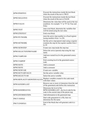
Downloaded 10 times

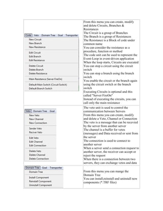
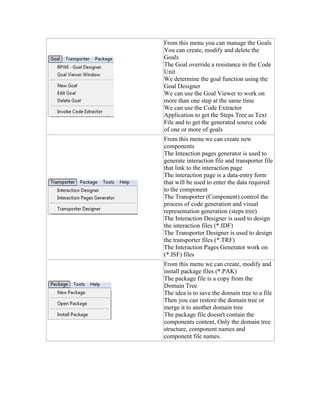

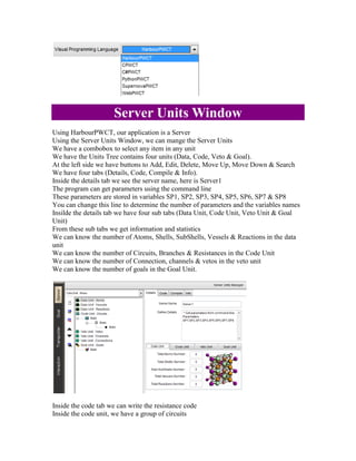

The document describes the features and interface of the Programming Without Coding Technology (PWCT) environment. The PWCT environment allows visual programming through a graphical interface and contains various windows and tools for visual programming, including a server units window to manage server code, a goal designer to create goals to override code, and designers for interactions and transporters. It provides features like visual programming languages, framework extensions, and supports multiple operating systems.


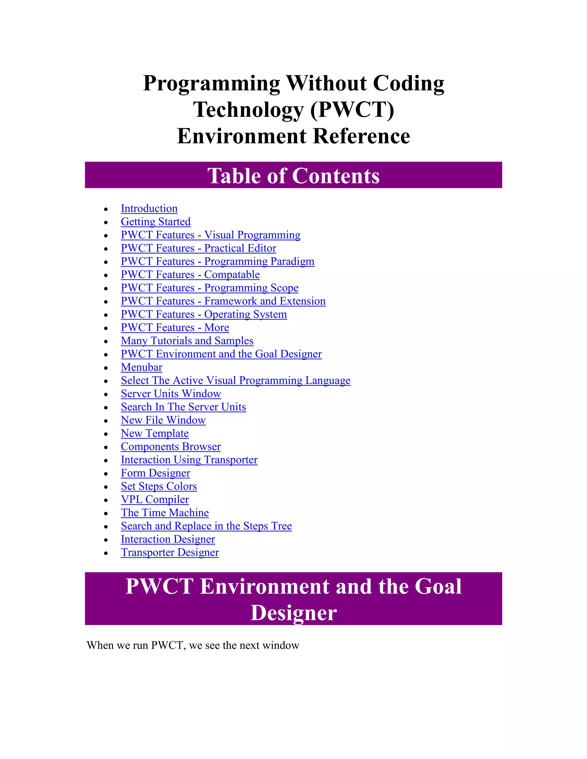
![[Mas 500] Software Development Strategies](https://cdn.slidesharecdn.com/ss_thumbnails/mas-500-2-software-stategies-131113120840-phpapp01-thumbnail.jpg?width=640&height=640&fit=bounds)


