The document provides detailed technical specifications for Profibus DP telegrams, including the structure, frame format, function codes, and parameters for master/slave communication. It outlines the process of parameterization, configuration checking, and diagnostics in Profibus networks. Key elements the document covers include telegram types, command functions, and the data unit exchanges between devices.
![PROFIBUS_Telegrams.doc PROFIBUS Certified Engineer Course, Version 7.0, December 2008 © A. Verwer Page 1 of 13
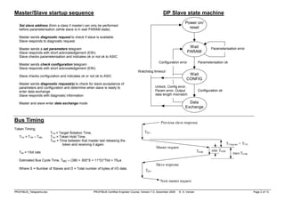
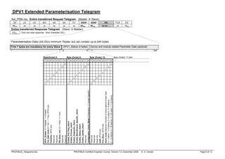
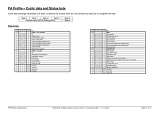
PROFIBUS DP – Telegrams
Telegram Frame Format:
SD LE LEr SDr DA SA FC DSAP SSAP PDU… FCS ED
SD: Start Delimiter
LE: Net Data Length = (DA+SA+FC+DSAP+SSAP+Len[PDU]) ≤ 249
(Protocol Data Unit [PDU] Length ≤ 244)
DA: Destination Address
SA: Source Address
FC: Function Code
DSAP: Destination Service Access Point
SSAP: Source Service Access Point
FCS: Frame Check Sequence
ED: End Delimiter, ED = 16 (22)
Function Code Byte:
0 b6 b5 b4 fc fc fc fc
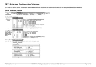
DPV0 Master/Master and Master/Slave Interactions:
Slave
Get Master Diagnostics, Upload
Class 1
Master
Class 2
Master
Data Exchange, Slave Diagnostics,
Set Parameters, Check Configuration,
Global Control
Data Exchange, Read Inputs,
Read Outputs, Slave Diagnostics,
Set Parameters, Check Configuration,
Get Configuration, Global Control
Set Slave Address
Download, Activate Bus Parameters,
Broadcast, Activate/Deactivate Slave,
Change Master Mode, Start/End Sequence
Address encoding:
XYYY YYYY
Service Access Points:
Service Master SAP Slave SAP
Data Exchange None None
Set Slave Address 3E (62) 37 (55)
Read Inputs 3E (62) 38 (56)
Read Outputs 3E (62) 39 (57)
Global Control 3E (62) 3A (58)
Get Configuration 3E (62) 3B (59)
Slave Diagnostics 3E (62) 3C (60)
Set Parameters 3E (62) 3D (61)
Check Configuration 3E (62) 3E (62)
DPV0 Master to Master functions 36 (54) 36 (54)
DPV1 Master class 1 functions 33 (51) 33 (51) or 32 (50)
DPV1 Resource Manager 32 (50) 31 (49)
DPV1 Master class 2 32 (50) 0 (0) … 30 (48)
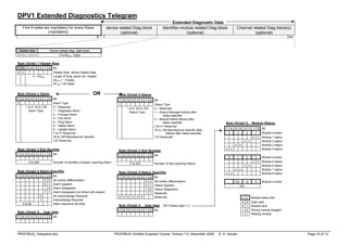
SD1 = 10 (16) - Telegrams of fixed length without a data field (eg Request_FDL_Status – look for new masters)
SD2 = 68 (104) - Telegrams with a variable length data field (SRD service)
SD3 = A2 (162) - Telegrams of fixed length with a constant-length data field (Data field is always 8 bytes)
SD4 = DC (220) - Token pass telegram
SC = E5 (229) - Short Acknowledgement telegram (Only one byte transmitted)
Always 0
1=Rqst, 0=Resp
Rqst: b5=frame count bit (alternates 0/1), b4=frame count valid
Resp: Station type (00=Slave, 01=Master not ready to enter token ring,
10= Master ready to enter token ring, 11= Master in token ring)
fc Request function (b6=1) Response function (b6=0)
0 ---- Ack positive (OK)
1 ---- Ack negative, user error (UE)
2 ---- Ack negative, no resource for response (RR)
3 SDA low (FMS only) Ack negative, SAP not activated (RS)
4 SDN low (Broadcast and multicast telegrams) ----
5 SDA high (FMS only) ----
6 SDN high (Broadcast and multicast telegrams) ----
7 ---- ----
8 ---- Low priority response to SRD (DL)
9 Request FDL status with reply Ack negative, no response (NR)
A (10) ---- High priority response to SRD (DH)
B (11) ---- ----
C (12) SRD low (Send and request data) Negative response to SRD, no resource (RDL)
D (13) SRD high (Send and request data) Negative response to SRD, no resource (RDH)
E (14) Request ID with reply ----
F (15) Request LSAP status with reply ----
Note all values shown on this page as: hex (dec)
X = Extended Addressing used (SAPs)
YYY YYYY = station address (7 bits)](https://image.slidesharecdn.com/14963387859366052097-250127020628-6f17de88/85/Profibus-DP-Telegrams-COURSE-How-to-pdf-1-320.jpg)
![PROFIBUS_Telegrams.doc PROFIBUS Certified Engineer Course, Version 7.0, December 2008 © A. Verwer Page 1 of 13
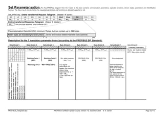
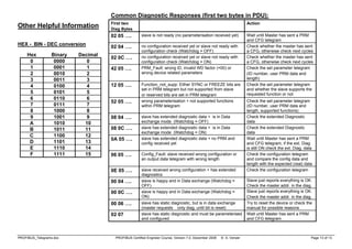
PROFIBUS DP – Telegrams
Telegram Frame Format:
SD LE LEr SDr DA SA FC DSAP SSAP PDU… FCS ED
SD: Start Delimiter
LE: Net Data Length = (DA+SA+FC+DSAP+SSAP+Len[PDU]) ≤ 249
(Protocol Data Unit [PDU] Length ≤ 244)
DA: Destination Address
SA: Source Address
FC: Function Code
DSAP: Destination Service Access Point
SSAP: Source Service Access Point
FCS: Frame Check Sequence
ED: End Delimiter, ED = 16 (22)
Function Code Byte:
0 b6 b5 b4 fc fc fc fc
DPV0 Master/Master and Master/Slave Interactions:
Slave
Get Master Diagnostics, Upload
Class 1
Master
Class 2
Master
Data Exchange, Slave Diagnostics,
Set Parameters, Check Configuration,
Global Control
Data Exchange, Read Inputs,
Read Outputs, Slave Diagnostics,
Set Parameters, Check Configuration,
Get Configuration, Global Control
Set Slave Address
Download, Activate Bus Parameters,
Broadcast, Activate/Deactivate Slave,
Change Master Mode, Start/End Sequence
Address encoding:
XYYY YYYY
Service Access Points:
Service Master SAP Slave SAP
Data Exchange None None
Set Slave Address 3E (62) 37 (55)
Read Inputs 3E (62) 38 (56)
Read Outputs 3E (62) 39 (57)
Global Control 3E (62) 3A (58)
Get Configuration 3E (62) 3B (59)
Slave Diagnostics 3E (62) 3C (60)
Set Parameters 3E (62) 3D (61)
Check Configuration 3E (62) 3E (62)
DPV0 Master to Master functions 36 (54) 36 (54)
DPV1 Master class 1 functions 33 (51) 33 (51) or 32 (50)
DPV1 Resource Manager 32 (50) 31 (49)
DPV1 Master class 2 32 (50) 0 (0) … 30 (48)
SD1 = 10 (16) - Telegrams of fixed length without a data field (eg Request_FDL_Status – look for new masters)
SD2 = 68 (104) - Telegrams with a variable length data field (SRD service)
SD3 = A2 (162) - Telegrams of fixed length with a constant-length data field (Data field is always 8 bytes)
SD4 = DC (220) - Token pass telegram
SC = E5 (229) - Short Acknowledgement telegram (Only one byte transmitted)
Always 0
1=Rqst, 0=Resp
Rqst: b5=frame count bit (alternates 0/1), b4=frame count valid
Resp: Station type (00=Slave, 01=Master not ready to enter token ring,
10= Master ready to enter token ring, 11= Master in token ring)
fc Request function (b6=1) Response function (b6=0)
0 ---- Ack positive (OK)
1 ---- Ack negative, user error (UE)
2 ---- Ack negative, no resource for response (RR)
3 SDA low (FMS only) Ack negative, SAP not activated (RS)
4 SDN low (Broadcast and multicast telegrams) ----
5 SDA high (FMS only) ----
6 SDN high (Broadcast and multicast telegrams) ----
7 ---- ----
8 ---- Low priority response to SRD (DL)
9 Request FDL status with reply Ack negative, no response (NR)
A (10) ---- High priority response to SRD (DH)
B (11) ---- ----
C (12) SRD low (Send and request data) Negative response to SRD, no resource (RDL)
D (13) SRD high (Send and request data) Negative response to SRD, no resource (RDH)
E (14) Request ID with reply ----
F (15) Request LSAP status with reply ----
Note all values shown on this page as: hex (dec)
X = Extended Addressing used (SAPs)
YYY YYYY = station address (7 bits)](https://image.slidesharecdn.com/14963387859366052097-250127020628-6f17de88/75/Profibus-DP-Telegrams-COURSE-How-to-pdf-1-2048.jpg)


![Using%20 modbus%20for%20process[1]](https://cdn.slidesharecdn.com/ss_thumbnails/using20modbus20for20process1-140402073109-phpapp01-thumbnail.jpg?width=640&height=640&fit=bounds)


