More Related Content

PPT

PPTX
Pressman_Pressman_SoftwareEngineeringPA_9e_Ch007_PPT.pptx 
PPTX
Pressman_Pressman_SoftwareEngineeringPA_9e_Ch007_PPT.pptx 
PPT

PPT
6. Requirement Modelinbbdhdhbdhhdbbdg.ppt 
PPT
Analysis modeling & scenario based modeling 
PPTX

PPT
SEUNIT3.ppt in software engineering subject Similar to Pressman_Pressman_SoftwareEngineeringPA_9e_Ch008_PPT.pptx

PDF
data modelling concepts.pdf software engineeringre 
PDF
Requirement Engineering.pdf 
PPTX

PPTX
Lecture_four-_Requirements_Modeling (1).pptx 
PPT
Analysis-Models jjjkkkkjgffffffttui3k3k3j3n 
PDF
Day01 01 software requirement concepts 
PPT

PDF
Requirement analysis with use case 
PDF
6. ch 5-understanding requirements 
PDF
6-180117160306. software engineering concepts 
PPTX

PPT

PPT

PPT

PPT

PPT
Data Flow Diagram and USe Case Diagram 
PPTX
Unit2 Software engineering UPTU 
PDF

PPT
CHAPTER 6 REQUIREMENTS MODELING: SCENARIO based Model , Class based moddel 
PDF
Requirement analysis and UML modelling in Software engineering Recently uploaded

PDF
TrakSYS Certified Engineer Certificate.pdf 
PPTX
High_Voltage_Insulation_Breakdown_With_Notes.pptx 
PPTX
Hack With India (1)-1.pptx chapter across all india 
PPTX
presentation-tenable-corporate-deck-ppt-version-english (1).pptx 
PPTX
CORROSION, TYPES, THEORIES, PREVENTION by Tanvi Kothawale.pptx 
PDF
Susan J. Masten and Mackenzie L. Davis - Principles of Environmental Engineer... 
PPTX
ADVANCED TRANSPORTATION ENGINEERING Unit-3.pptx 
PPTX
Research Methodology (RM) BRMK557 Module-02 
PPTX
low power design COURSE PREREQUISITES Digital System Design, VLSI Design & El... 
PDF
Layer 1 Blockchain Ecosystem — Executive Brief (Jan 2026) 
PDF
Engineering Mindset for Everyday Leadership — James Afful [Emerging Leaders o... 
PDF
DIMENSION REDUCTION FOR SCRIPT CLASSIFICATION- PRINTED INDIAN DOCUMENTS 
PDF
Interaction with IIT Khatragpur for Infrastructure Development 
PDF
BO049FHDMO 0.49 Inch Micro OLED Datasheet 
PDF
-الشهادة وعتماد 2.pdf كلريوس الهندسة المدنية والعمارية تخصص هندسة المساحة 
PPTX
Phishing Website Detection by Machine Learning Techniques Presentation.pptx 
PPTX
Amperes Circuital Law and its appliocations 
PPTX
mechanical measurements course lecture2.pptx 
PPTX
Basics_of_Electronics_Simplebysreeragsr.pptx 
PDF
12th International Conference on Computer Science, Information Technology and... Pressman_Pressman_SoftwareEngineeringPA_9e_Ch008_PPT.pptx
- 1.
Because learning changeseverything.®
Chapter 8
Requirements Modeling – A
Recommended Approach
Part Two - Mobility.
© 2020 McGraw Hill. All rights reserved. Authorized only for instructor use in the classroom.
No reproduction or further distribution permitted without the prior written consent of McGraw Hill.
- 2.
© McGraw Hill
RequirementsAnalysis
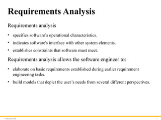
Requirements analysis
• specifies software’s operational characteristics.
• indicates software's interface with other system elements.
• establishes constraints that software must meet.
Requirements analysis allows the software engineer to:
• elaborate on basic requirements established during earlier requirement
engineering tasks.
• build models that depict the user’s needs from several different perspectives.
2
- 3.
© McGraw Hill
RequirementsModels
• Scenario-based models depict requirements from the point of
view of various system “actors.”
• Class-oriented models represent object-oriented classes
(attributes and operations) and how classes collaborate to
achieve system requirements.
• Behavioral models depict how the software reacts to internal
or external “events.”
• Data models depict the information domain for the problem.
• Flow-oriented models represent functional elements of the
system and how they transform data in the system.
3
- 4.
- 5.
© McGraw Hill
Rulesof Thumb
• The level of abstraction should be relatively high - focus on
requirements visible in problem or business domains.
• Analysis model should provide insight into information
domain, function, and behavior of the software.
• Delay consideration of infrastructure and other non-functional
models until later in the modeling activity.
• The analysis model provides value to all stakeholders keep the
model as simple as it can be.
5
- 6.
© McGraw Hill
RequirementsModeling Principles
• Principle 1. The information domain of a problem must be
represented and understood.
• Principle 2. The functions that the software performs must be
defined.
• Principle 3. The behavior of the software (as a consequence of
external events) must be represented.
• Principle 4. The models that depict information, function, and
behavior must be partitioned in a manner that uncovers detail
in a layered (or hierarchical) fashion.
• Principle 5. The analysis task should move from essential
information toward implementation detail.
6
- 7.
© McGraw Hill
Scenario-BasedModeling: Actors and
Profiles
A UML actor models an entity that interacts with a system object.
• Actors may represent roles played by human stakeholders or external
hardware as they interact with system objects by exchanging information.
A UML profile provides a way of extending an existing model to
other domains or platforms.
• This might allow you to revise the model of a Web-based system and model
the system for various mobile platforms.
• Profiles might also be used to model the system from the viewpoints of
different users.
7
- 8.
© McGraw Hill8
Use Cases
• Use case as a “contract for behavior” and more formal than a
user story.
• Use-cases are simply an aid to defining what exists outside the
system (actors) and what should be performed by the system
(use-cases).
1. What should we write about?
2. How much should we write about it?
3. How detailed should we make our description?
4. How should we organize the description?
- 9.
© McGraw Hill9
What to Write About?
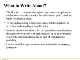
• The first two requirements engineering tasks—inception and
elicitation—provide you with the information you’ll need to
begin writing use cases.
• To begin developing a set of use cases, list the functions or
activities performed by a specific actor.
• You can obtain these from a list of required system functions,
through conversations with stakeholders, or by an evaluation
of activity diagrams developed as part of requirements
modeling.
• Use cases of this type are sometimes referred to as primary
scenarios.
- 10.
© McGraw Hill10
Alternative Interactions
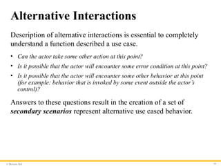
Description of alternative interactions is essential to completely
understand a function described a use case.
• Can the actor take some other action at this point?
• Is it possible that the actor will encounter some error condition at this point?
• Is it possible that the actor will encounter some other behavior at this point
(for example: behavior that is invoked by some event outside the actor’s
control)?
Answers to these questions result in the creation of a set of
secondary scenarios represent alternative use cased behavior.
- 11.
© McGraw Hill11
Defining Exceptions
An exception describes a situation (either a failure condition or
an alternative chosen by the actor) that causes the system to
exhibit somewhat different behavior.
Questions to ask:
• Are there cases in which some “validation function” occurs during this use
case?
• Are there cases in which a supporting function (or actor) will fail to
respond appropriately?
• Can poor system performance result in unexpected or improper user
actions?
- 12.
© McGraw Hill12
Documenting Use Cases
• What are the main tasks or functions that are performed by the
actor?
• What system information will the actor acquire, produce or
change?
• Will the actor have to inform the system about changes in the
external environment?
• What information does the actor desire from the system?
• Does the actor wish to be informed about unexpected changes?
• What are the preconditions, triggers, exceptions, and open
issues?
- 13.
© McGraw Hill13
Use Case Diagram
Access the text alternative for slide images.
- 14.
© McGraw Hill14
Class-Based Modeling
Class-based modeling represents:
• objects that the system will manipulate.
• operations (also called methods or services) that will be applied to the objects
to effect the manipulation.
• relationships (some hierarchical) between the objects.
• collaborations that occur between the classes that are defined.
The elements of a class-based model include classes and objects,
attributes, operations, CRC models, UML class diagrams.
- 15.
© McGraw Hill15
Identifying Analysis Classes
Examining the usage scenarios developed as part of the
requirements model and perform a "grammatical parse“.
• Classes are determined by underlining each noun or noun phrase and entering
it into a simple table.
• Synonyms should be noted.
• If the class (noun) is required to implement a solution, then it is part of the
solution space; otherwise, if a class is necessary only to describe a solution, it
is part of the problem space.
But what should we look for once all of the nouns have been
isolated?
- 16.
© McGraw Hill16
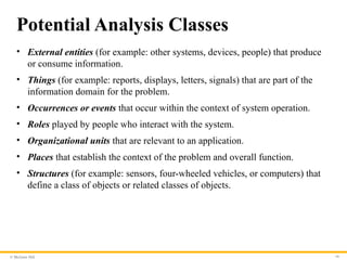
Potential Analysis Classes
• External entities (for example: other systems, devices, people) that produce
or consume information.
• Things (for example: reports, displays, letters, signals) that are part of the
information domain for the problem.
• Occurrences or events that occur within the context of system operation.
• Roles played by people who interact with the system.
• Organizational units that are relevant to an application.
• Places that establish the context of the problem and overall function.
• Structures (for example: sensors, four-wheeled vehicles, or computers) that
define a class of objects or related classes of objects.
- 17.
© McGraw Hill17
Analysis Class Selection
• Retained information. Potential class will be useful during analysis only if
information about it must be remembered.
• Needed services. Potential class must have a set of identifiable operations
that can change the value of its attributes in some way.
• Multiple attributes. Focus should be on "major" information; a class with a
single attribute may be better represented as an attribute of another class.
• Common attributes. A set of attributes can be defined for the potential class
and the attributes apply to all instances of the class.
• Common operations. A set of operations can be defined for the potential
class and the operations apply to all instances of the class.
• Essential requirements. External entities that appear in the problem space
and produce or consume information essential to the solution will usually
be defined as analysis classes in the model.
- 18.
© McGraw Hill18
Defining Attributes
• Attributes describe a class that has been selected for inclusion
in the analysis model.
• It is the attributes that define the class—that clarify what is
meant by the class in the context of the problem space.
• To develop a meaningful set of attributes for an analysis class,
you should study each use case and select those “things” that
reasonably “belong” to the class.
• What data items(composite and/or elementary) fully define this
class in the context of the problem at hand?
- 19.
© McGraw Hill19
Defining Operations
• Operations define the behavior of an object.
• Operations they can generally be divided into four broad categories:
1. Operations that manipulate data in some way.
2. Operations that perform a computation.
3. Operations that inquire about the state.
4. Operations that monitor an object for the occurrence of a controlling
event.
• These functions are accomplished by operating on attributes and/or
associations.
• Therefore, an operation must have “knowledge” of the class attributes and
associations.
- 20.
© McGraw Hill20
CRC Modeling
• Class-responsibility-collaborator (CRC) modeling provides a
simple means for identifying and organizing the classes that
are relevant to system or product requirements.
• A CRC model is really a collection of standard index cards that
represent classes.
• The cards are divided into three sections:
1. Along the top of the card you write the name of the class.
2. list the class responsibilities on the left.
3. list the collaborators on the right.
- 21.
© McGraw Hill21
CRC Cards
Access the text alternative for slide images.
- 22.
© McGraw Hill22
CRC Model Review Process
1. All stakeholders in the review (of the CRC model) are given a subset of
the CRC model index cards. No reviewer should have two cards that
collaborate.
2. The review leader reads the use case deliberately. As the review leader
comes to a named object, she passes a token to the person holding the
corresponding class index card.
3. When the token is passed, the holder of the class card is asked to describe
the responsibilities noted on the card. The group determines whether one
of the responsibilities satisfies the use case requirement.
4. If an error is found, modifications are made to the cards. This may include
the definition of new classes (CRC index cards) or revising lists of
responsibilities or collaborations on existing cards.
- 23.
© McGraw Hill23
Functional Modeling
• The functional model addresses two application processing
elements:
1. user-observable functionality that is delivered by the app to
end users.
2. operations contained within analysis classes that implement
behaviors associated with the class.
• UML activity diagrams can be used to represent processing
details.
• UML activity diagram supplements a use case by providing a
graphical representation of the flow of interaction within a
specific scenario.
- 24.
© McGraw Hill24
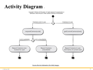
Activity Diagram 1
Access the text alternative for slide images.
- 25.
© McGraw Hill25
Sequence Diagram 1
• The UML sequence diagram can be used for behavioral
modeling.
• Sequence diagrams can also be used to show how events cause
transitions from object to object.
• Once events have been identified by examining a use case, the
modeler creates a sequence diagram—a representation of how
events cause flow from one object to another as a function of
time.
• Sequence diagram is a shorthand version of a use case.
- 26.
© McGraw Hill26
Sequence Diagram 2
Access the text alternative for slide images.
- 27.
© McGraw Hill27
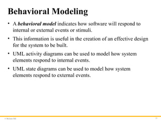
Behavioral Modeling
• A behavioral model indicates how software will respond to
internal or external events or stimuli.
• This information is useful in the creation of an effective design
for the system to be built.
• UML activity diagrams can be used to model how system
elements respond to internal events.
• UML state diagrams can be used to model how system
elements respond to external events.
- 28.
© McGraw Hill28
Creating Behavioral Models
1. Evaluate all use cases to fully understand the sequence of
interaction within the system.
2. Identify events that drive the interaction sequence and
understand how these events relate to specific objects.
3. Create a sequence diagram for each use case.
4. Build a state diagram for the system.
5. Review the behavioral model for accuracy and consistency.
- 29.
© McGraw Hill29
Identifying Events
• A use case represents a sequence of activities that involves
actors and the system.
• An event occurs whenever the system and an actor exchange
information.
• An event is not the information that has been exchanged, but
rather the fact that information has been exchanged.
• A use case needs to be examined for points of information
exchange.
• Events are used to trigger state transitions.
- 30.
© McGraw Hill30
State Diagram
Access the text alternative for slide images.
- 31.
© McGraw Hill31
Activity Diagram 2
Access the text alternative for slide images.
- 32.
© McGraw Hill32
Swimlane Diagrams
• The UML swimlane diagram is a useful variation of the activity diagram
that allows you to represent the flow of activities described by the use case.
• Swimlane diagrams indicate which actor (if there are multiple actors
involved in a specific use case) or analysis class has responsibility for the
action described by an activity rectangle.
• Responsibilities are represented as parallel segments that divide the
diagram vertically, like the lanes in a swimming pool.
- 33.
© McGraw Hill33
Swimlane Diagram
Access the text alternative for slide images.
- 34.
Because learning changeseverything.®
www.mheducation.com
End of Main Content
© 2020 McGraw Hill. All rights reserved. Authorized only for instructor use in the classroom.
No reproduction or further distribution permitted without the prior written consent of McGraw Hill.
- 35.
© McGraw Hill35
Accessibility Content: Text Alternatives for Images
- 36.
© McGraw Hill
ABridge – Text Alternative
Return to parent-slide containing images.
An illustration displays a bridge. Three circles represent the system
description, analysis model, and design model. The analysis model
overlaps with the system description, and the design model.
Return to parent-slide containing images.
36
- 37.
© McGraw Hill
UseCase Diagram – Text Alternative
Return to parent-slide containing images.
An illustration displays a case diagram. The homeowner is
connected to the three use cases of a safehome. The use cases are,
access camera surveillance via the internet, configures safehome
system parameters, and sets alar. The access camera surveillance
via the internet is further connected to cameras.
Return to parent-slide containing images.
37
- 38.
© McGraw Hill
CRCCards – Text Alternative
Return to parent-slide containing images.
An illustration displays CRC cards. The title reads class: floor plan.
The space below the title reads description. The card is further
divided into two columns titled responsibility, and collaborator.
The responsibility reads defines floor plan name or type; manages
floor plan positioning; scales floor plan for display; incorporates
walls, door, and windows, and shows position of video cameras.
The collaborator reads, wall on the column corresponding to
incorporates wall, doors, and windows; and camera in the column
respective to shows position of video cameras.
Return to parent-slide containing images.
38
- 39.
© McGraw Hill
ActivityDiagram 1 – Text Alternative
Return to parent-slide containing images.
A flowchart displays an activity diagram. The diagram starts with
two possibilities, camera not in use, and camera in use. If the
camera in use, get current camera user, and then report camera in
use and home of current user. If the camera not in use, the request
camera lock. If the camera lock is available, then report camera
now locked for user. If the lock is unavailable, then report camera
unavailable.
Return to parent-slide containing images.
39
- 40.
© McGraw Hill
SequenceDiagram 2 – Text Alternative
Return to parent-slide containing images.
The sequence diagram has four life lines which are labeled, from left to
right, homeowner, control panel, system and sensors. When the system is
ready the homeowner enters a password which is relayed to the control
panel. The control panel begins by reading the message and then
performs a compare of the password entered. When comparing the
control panel sends a lookup request to the system which return a result.
If the password is correct the system sends an activation request to the
sensors which over a duration sends a successful activation message to
the control panel which further the relays the successful activation
message to the homeowner. If the password entered is wrong the
homeowner has a maximum number of three tries to enter the correct
password. If the three tries are exceeded the system is locked. Locked
system has looped timer.
Return to parent-slide containing images.
40
- 41.
© McGraw Hill
StateDiagram – Text Alternative
Return to parent-slide containing images.
The state diagram shows an initial state of the process. After the key is hit
the diagram shows a reading state. The reading state transitions the
entered password to a comparing state. The comparing state is a shown as
a class with a validate password operation. The comparing state has a
loop, if password equals incorrect and number of tries greater than
maximum number of tries. When number of tries exceeds maximum
number of tries the comparing state transitions to a locked state. A locked
state has a loop with timer greater than locked time. When timer greater
than locked time the locked state transitions back to the reading state. If
the password entered is correct the comparing state transitions to a
selecting state. Upon a successful activation selecting state transitions
back to the reading state.
Return to parent-slide containing images.
41
- 42.
© McGraw Hill
ActivityDiagram 2 – Text Alternative
Return to parent-slide containing images.
The activity diagram begins with an initial state. The next activity state is enter
password and user ID. This initiates a condition. If a password and ID are valid
and if a password and ID are invalid. If invalid, then prompt for reentry activity.
This entails another condition. If input tries remain the process loops back to the
initial condition at enter password and ID if no input tries remain the process
reaches an end state. If in the initial condition the valid ID and password were
entered the next activity is select major function here other functions may also
be selected. After this next activity is select surveillance. After selecting
surveillance, the user can choose thumbnail views or select a specific camera.
Selecting thumbnail, leads to select specific camera thumbnails and selecting a
specific camera leads to select camera icon. Both, select specific camera
thumbnails and select camera icon lead to view camera in output in labeled
window. This leads to prompt for another view. This leads to two condition. First
exit this function which leads to a final state or see another camera which loops
back to the condition under select surveillance.
Return to parent-slide containing images.
42
- 43.
© McGraw Hill
SwimlaneDiagram – Text Alternative
Return to parent-slide containing images.
The swimlane diagram is illustrated within a table. The three column headings of the
table are: homeowner, camera and interface. The flow begins with an initial state in
homeowner. The next activity state is enter password and user ID. This initiates a
condition in the interface. If a password and ID are valid and if a password and ID are
invalid. If invalid, then prompt for reentry activity. This entails another condition also
within interface. If input tries remain the process loops back to the initial condition at
enter password and ID if no input tries remain the process reaches an end state. If in the
initial condition the valid ID and password were entered the next activity is select major
function, under homeowner, here other functions may also be selected. After this next
activity is select surveillance. After selecting surveillance, the user can choose thumbnail
views or select a specific camera. Selecting thumbnail, leads to select specific camera
thumbnails and selecting a specific camera leads to select camera icon. Both, select
specific camera thumbnails and select camera icon lead to, the activity, generate video
output, under the column camera. Generate video output leads to view camera in output
in labeled window, under homeowner. This leads to prompt for another view under
interface. This leads to two conditions. First exit this function which leads to a final state
or see another camera which loops back to the condition under select surveillance.
Return to parent-slide containing images.
43