This document summarizes a new nesting technique for packing similar parts onto a sheet using a lattice packing algorithm. The algorithm finds the densest lattice structure by placing parts along the boundary of a "hodograph", which represents the set of points where one part can be placed without overlapping an adjacent part. This allows parts to be densely packed in a regular arrangement while accounting for variations in part sizes and shapes. The algorithm aims to maximize sheet utilization by iteratively placing parts in the best available lattice positions according to a contour matching index.
![Abstract
The packing problem is very important to manufacturing
industry. This paper deals with the problem of searching
for the densest lattice packing of identical parts on the
rectangular sheet and proposes a new approach to the
nesting problems of nearly identical or similar parts. A
new nesting technique has been developed by
incorporating a lattice packing algorithm in order to find
the best arrangements for similar parts. Based on the
lattice structure, parts are placed on the sheet by utilising
hodograph and contour matching techniques. This paper
is a first approach to the use of lattice packing in the
solution of similar part nesting. The proposed algorithm
has useful applications in industry, particularly clothing
manufacture. The example of solving of the real
problem is given.
Keywords: Lattice packing, Nesting
1. Introduction
Packing problems are optimization problems concerned
with finding good arrangement of multiple items without
overlap in larger containing regions. This type of
problem is encountered in many areas of business and
industry. The objective of the packing process is to
maximize the utilization of material. A classification
and up−to−date bibliographies on the 2D packing
problems can be found in [1].
The lattice packing problem is the task to find a
lattice of minimal determinant. The ratio of the area of
the object to the determinant of such an optimal lattice is
called the density of a densest lattice packing. It can be
interpreted as the maximal proportion of the space that
can be occupied by non−overlapping lattice translates of
the object. The problems of lattice packing of geometric
objects were considered in the works of Refs. [2,3,4].
In some industrial packing problems, the large set of
parts consists of several sets of parts which are much
smaller than the container. Furthermore, the parts can
vary somewhat in size and shape according to the needs
of customers. This paper addresses these aspects of the
actual layout problem based on the densest lattice
packing algorithm as well.
2. Definitions, Background and Lattice
Packing
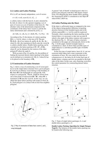
2.1 Minkowski Sum and Hodograph
The Minkowski sum and difference are powerful and
effective preprocessing tools for polygon intersection
and packing problems. Comprehensive descriptions of
the algorithm have been presented in [5,6,7].
The shape of parts to be placed is approximated as a
polygon with n vertices. As the number of vertices
increases, curved edges on the blank can be
approximated to any desired accuracy. Given two
polygons, A and B, the Minkowski sum is defined as the
summation of each point in A with each point in B,
A ⊕ B = {a + b | a ∈ A, b ∈ B} (1)
The Minkowski difference is defined as
A B = {a − b | a ∈ A, b ∈ B} (2)
Let −A = 2
A denote the se complement of A.
−A = {−a | a ∈ A} (3)
defines a point reflection of A at the origin. The
hodograph Hij of a polygon Si relative to a Sj, 1≤i,j≤k,
can be defined by using the Minkowski sum:
Hij = −(Sj ⊕ −(Si bi)) (4)
The hodograph Hij is the set of points in 2
onto which
the reference point bi of Si can be placed such that Si
and Sj do not overlap. Both Si and Sj must not be
rotated. For lattice packing, the same polygon is
repeated on the sheet. So polygons Si and Sj are same
ones. Boundary of the hodograph Hij can be called in
some ways such as a dense placement function, 0−level
surface of the Φ−function[2,3] or No−fit−Polygon[8].
Fig. 1. Example of a hodograph Hij (shade area) of a
polygon Si relative to a polygon Sj and its boundary for
dense lattice packing.
Fig. 1 shows an example of hodograph for two identical
polygons Si and Sj. Boundary of hodograph is the locus
of points traced by the reference point of Si (the orbital
polygon) when it slides along the contour of Sj (the
stationary polygon). The use of hodograph makes to get
a feasible(without intersecting) and dense layout.
Lattice Based Packing of 2D Similar Parts
Guk−Chan Han
Institute for Algorithms and Scientific Computing(SCAI)
Fraunhofer, Schloss Birlinghoven, 53757 Sankt Augustin, Germany
Email: Guk−Chan.Han@scai.fhg.de](https://image.slidesharecdn.com/8505be28-51e9-4af6-83f9-02cc37a8bbf8-160408054957/85/presentation-geseke-1-320.jpg)
![Abstract
The packing problem is very important to manufacturing
industry. This paper deals with the problem of searching
for the densest lattice packing of identical parts on the
rectangular sheet and proposes a new approach to the
nesting problems of nearly identical or similar parts. A
new nesting technique has been developed by
incorporating a lattice packing algorithm in order to find
the best arrangements for similar parts. Based on the
lattice structure, parts are placed on the sheet by utilising
hodograph and contour matching techniques. This paper
is a first approach to the use of lattice packing in the
solution of similar part nesting. The proposed algorithm
has useful applications in industry, particularly clothing
manufacture. The example of solving of the real
problem is given.
Keywords: Lattice packing, Nesting
1. Introduction
Packing problems are optimization problems concerned
with finding good arrangement of multiple items without
overlap in larger containing regions. This type of
problem is encountered in many areas of business and
industry. The objective of the packing process is to
maximize the utilization of material. A classification
and up−to−date bibliographies on the 2D packing
problems can be found in [1].
The lattice packing problem is the task to find a
lattice of minimal determinant. The ratio of the area of
the object to the determinant of such an optimal lattice is
called the density of a densest lattice packing. It can be
interpreted as the maximal proportion of the space that
can be occupied by non−overlapping lattice translates of
the object. The problems of lattice packing of geometric
objects were considered in the works of Refs. [2,3,4].
In some industrial packing problems, the large set of
parts consists of several sets of parts which are much
smaller than the container. Furthermore, the parts can
vary somewhat in size and shape according to the needs
of customers. This paper addresses these aspects of the
actual layout problem based on the densest lattice
packing algorithm as well.
2. Definitions, Background and Lattice
Packing
2.1 Minkowski Sum and Hodograph
The Minkowski sum and difference are powerful and
effective preprocessing tools for polygon intersection
and packing problems. Comprehensive descriptions of
the algorithm have been presented in [5,6,7].
The shape of parts to be placed is approximated as a
polygon with n vertices. As the number of vertices
increases, curved edges on the blank can be
approximated to any desired accuracy. Given two
polygons, A and B, the Minkowski sum is defined as the
summation of each point in A with each point in B,
A ⊕ B = {a + b | a ∈ A, b ∈ B} (1)
The Minkowski difference is defined as
A B = {a − b | a ∈ A, b ∈ B} (2)
Let −A = 2
A denote the se complement of A.
−A = {−a | a ∈ A} (3)
defines a point reflection of A at the origin. The
hodograph Hij of a polygon Si relative to a Sj, 1≤i,j≤k,
can be defined by using the Minkowski sum:
Hij = −(Sj ⊕ −(Si bi)) (4)
The hodograph Hij is the set of points in 2
onto which
the reference point bi of Si can be placed such that Si
and Sj do not overlap. Both Si and Sj must not be
rotated. For lattice packing, the same polygon is
repeated on the sheet. So polygons Si and Sj are same
ones. Boundary of the hodograph Hij can be called in
some ways such as a dense placement function, 0−level
surface of the Φ−function[2,3] or No−fit−Polygon[8].
Fig. 1. Example of a hodograph Hij (shade area) of a
polygon Si relative to a polygon Sj and its boundary for
dense lattice packing.
Fig. 1 shows an example of hodograph for two identical
polygons Si and Sj. Boundary of hodograph is the locus
of points traced by the reference point of Si (the orbital
polygon) when it slides along the contour of Sj (the
stationary polygon). The use of hodograph makes to get
a feasible(without intersecting) and dense layout.
Lattice Based Packing of 2D Similar Parts
Guk−Chan Han
Institute for Algorithms and Scientific Computing(SCAI)
Fraunhofer, Schloss Birlinghoven, 53757 Sankt Augustin, Germany
Email: Guk−Chan.Han@scai.fhg.de](https://image.slidesharecdn.com/8505be28-51e9-4af6-83f9-02cc37a8bbf8-160408054957/75/presentation-geseke-1-2048.jpg)