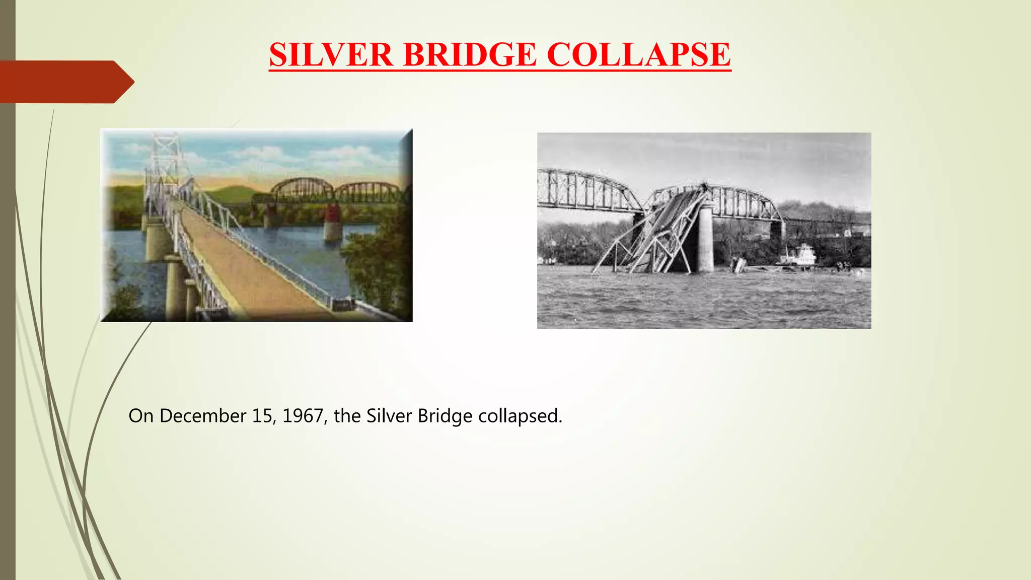
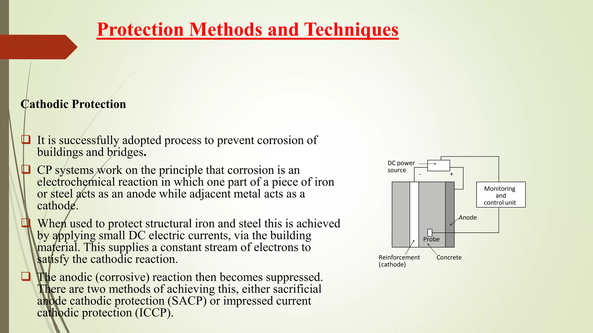
Corrosion failures in buildings and bridges; history and
protection techniques
____________________________________
IQRA MALIK (00000118276)
Contents_____________________________
 Introduction
Purpose
History
 Testing Standards
Experimental Approaches
Methods and Failure Analysis
 Causes of failure
Permeability of concrete.
Thermal movement:
 Conclusion and future recommendations
 References
Corrosion failures in buildings and bridges; history and
protection techniques
 Corrosion is defined as the deterioration of materials by reaction to its environment.
 Corrosion is probably the single most serious cause of deterioration of reinforced
concrete structures.
 Corrosion is always a serious problem in reinforced concrete.
 Very serious bridges and building corrosion occur in many parts of the world so
because of this a high degree of attention is paid to the selection of coating system.
 Usually, SCC occurs in buildings and in SCC most of the surface remains
unattacked, but with fine cracks penetrating into the material.
INTRODUCTION
HISTORY
Collapse of Mianus River Bridge
 It collapse on June 28, 1983
 The Mianus river bridge was a pin and hanger
assembly design.
Reason for Failure:
 The problem was caused by rust formation within the
bearing on the pin.
 The extra load on the remaining pin started a fatigue
crack at a sharp corner on the pin. When it failed
catastrophically, the deck was supported at just three
corners.
 When two heavy trucks and a car entered the section,
the remaining expansion joint failed, and the deck
crashed into the river below
COLLAPSE OF THE QUEBEC BRIDGE
It happened in 1916
Reasons for failure
 Inaccurate theoretical estimates of
the bridge's weight
 Stress corrosion cracking or
corrosion fatigue
SILVER BRIDGE COLLAPSE
On December 15, 1967, the Silver Bridge collapsed.
Reason for Failure:
 The fracture was caused from a minute crack formed during the casting of the steel eye-bar.
 Stress corrosion and corrosion fatigue allowed the crack to grow, causing the failure of the entire
structure.
 At the time of construction, the steel used was not known for overcoming to corrosion fatigue and stress
corrosion.
 The first thing to state is that carbonation and chloride ions
equal a lot of corrosion.
 The carbonation and chloride ions diffuse through the
concrete until the reach the embedded steel, spalling as a
result
 Then the pH is lower by the presence of the chloride ions
Mechanisms in concrete structures
 This corrosion process also requires oxygen diffused through the concrete, set-up an
electrochemical reaction.
 The process is increased by existence of voids in the concrete adjacent to steel.
Experimental work
log I
Anodic
polarization
curve
Cathodic
polarization
curve
2
1
3
4
5
E cor r
I cor r
 Polarization Curve for Steel in concrete.
Carbonation is the result of the chemical reaction between carbon dioxide gases in the atmosphere and the
alkaline hydroxides in the concrete.
Like many other gases, carbon dioxide dissolves in water to form an acid. Unlike most other acids, the
carbonic acid does not attack the cement paste, but rather neutralizes the alkalis in the pore water, mainly
forming calcium carbonate:
CO2 + H O2 → H CO2
HCO2 +Ca (OH)2 → CaCO3 + 2H O2
The carbonation process occurs quickly when the concrete cover is not very thick. It may also occur when
the concrete cover over the steel bars is thick because the carbonation transformation will happen as a result
of the existence of pore voids open in the concrete that assist the quick propagation of CO2 inside the
concrete.
CARBONATION IN RC STRUCTURES
 The carbonation process can occur when the alkalinity in voids is relatively small. This happens when the
cement content is small and water-to-cement (w/c) ratio is high and also due to a bad curing process during
construction.
 When the concrete is affected by carbonation, the value of alkalinity will drop from pH 11–13 to pH < 8, as
shown in figure. At this level of alkalinity, the passive layer protection cannot protect steel, so the corrosion
process will start.
 Carbonation can be observed and measured easily.
 The pH indicator is the proportion of phenolphthalein solution in water and alcohol, which will be sprayed
or painted on the concrete surface that is expected to be affected by carbonation; phenolphthalein will
change its color by change of pH.
 Phenolphthalein is colorless when pH is low (the carbonation).
 It changes to the color pink when the pH increases (concrete without carbonation).
 This can be measured by taking samples of concrete (usually the part of the cover that falls) so that the
surface will be ready for the test or to crack part of the concrete when periodic maintenance is performed.
 The surface to be measured by the amount of pH should be clean and away from dust and other fine
materials. From figure it can be seen that there is a different pH when carbonation is present in or absent
from concrete.
.
CARBONATION IN RC STRUCTURES
1 2 3
8
12
9
10
11
10 20 30 40 50
Distance from Surfaces, mm
 Relation between carbonation depth and level of pH values
CASE HISTORY
 Fatigue and corrosion of bridges is mentioned as an important cause of bridges collapse or the
combination of overloading and fatigue.
 While in the case of steel bridges the corrosion is associated to the direct attack of the environment, in
the case of the steel used as concrete bridges reinforcement, its damage is the result of complex
interactions.
 The reinforcing steel will not corrode unless the PH of the concrete drops due to carbonation or the
chloride content of the concrete reaches the corrosion threshold of the reinforcement.
Experimental work
1
10
100
1000
Duration of salt spray corrosion
%4.5 2.5 % 1 %
 Apostolopoulos [tested under laboratory conditions a
steel alloy (S500s, Tempcore), to study the effect of
the strain level and the corrosion duration on the
number of loading cycles for low cycle failure.
 The corrosive environment consisted of a NaCl
solution, sprayed onto the material at 35 0C within a
special environmental chamber.
 Corrosion effects were realized through weighing of
the specimen during the testing period.
Experimental work
 Three different levels of strain were considered about the zero-stress condition (±
1%, ± 2.5%, and ± 4.5%), for corrosion durations from 10 to 90 days.
 Up to a 14% loss of the specimen mass was measured.
 After the different periods of corrosion exposition, the sample was tested for low
cycle fatigue strength.
 In order to objectively assess the relative effect of corrosion duration and strain
level.
 where O is the output (cycles to failure) and I are the inputs (the strain level or the
days of corrosion duration
Experimental work
-0.9
-0.8
-0.7
-0.6
-0.5
-0.4
0 10 20 30 45 60 90
to 2.5 %1 2.5 to 4.5 %
Strain level ,
Strain level ,
Experimental work
 It should be noted that these experimental
results could be underestimating the
combined effect of corrosion and
stressing.
 As the exposition to corrosion and the
stressing were not simultaneous.
-0.04
-0.03
-0.02
-0.01
0
0.01
0 to 10 to 2010 30to20 to30 40 to 5040 50 to 60
1_0% 2_5% _5%4
Sensitivity of the days to failure to strain level and
exposition duration (with data from Apostolopoulos)
Experimental work
 Nakamura and Suzumura report the laboratory testing of galvanized wires used in suspension and
cable-stayed bridges.
 The testing procedure consisted of producing corroded wires in laboratory, which were testing for
fatigue strength in dry and wet conditions.
 Results validated the effectiveness of the zinc layer to preserve the properties of the wire, and the
low concentration of diffusive hydrogen into the material.
 However, they associate the fracture of the specimens to a combination effect, involving cyclic
stresses and diffusive hydrogen.
Experimental work
 Ahn and Reddy report a study aimed at assessing the effect of type of loading (static, fatigue) and
water/cement ratios on the durability of steel reinforced concrete beams.
 They find that cyclic loading and corrosion duration influences the ultimate strength of the
elements, in a range from 22 to 14%, as a function of the corrosion environment.
 Also, that beams subjected to fatigue loading deteriorated faster than those statically loaded.
 The experimental setup was based upon simply supported beams.
Causes of Cracks in concrete structures
The principal causes of occurrence of cracks in a building are as follows:
Permeability of concrete.
low permeability is the key to its durability.
Concrete permeability is controlled by factors
 water-cement ratio,
 degree of hydration/curing,
 air voids due to deficient compaction,
 micro-cracks due to loading and cyclic exposure to thermal variations.
The first three are allied to the concrete strength as well. The permeability of the concrete is a
direct function of the porosity and interconnection of pores of the cement paste.
Causes of Cracks in concrete structures
Thermal movement:
Thermal movement is one of the most important causes of cracking in buildings. All materials more or less
expand on heating and contract on cooling. The thermal movement in a component depends on a number of
factors such as temperature variations, dimensions, coefficient of thermal expansion and some other
physical properties of materials.
Thermal joints can be avoided by introducing expansion joints, control joints and slip joints. In structures
having rigid frames or shell roofs where provision of movement joints is not structurally feasible, thermal
stresses have to be taken into account in the structural design itself to enable the structure to withstand
thermal stresses without developing any undesirable cracks.
Protection Methods and Techniques
Following methods are used to protect this steel reinforcement concrete structures.
Coatings:
 Epoxy coatings are applied to concrete reinforcing bars in critical environment. An alkaline
environment does not harm the epoxy coating.
 A few organic corrosion resistant coating (paints) such as zinc dust primer, protect by becoming
sacrificial anodes and thus making the steel a cathode. The steel must be tightly packed and within the
few angstrom units of the surface of metal. These paints are called zinc rich primer and paints.
Protection Methods and Techniques
Corrosion Inhibitors
 MCI-corrosion inhibitors protect the reinforcing steel against the corrosion in both oxidation ranges:
cathode and anode range.
 In distinction from some other types of corrosion inhibitors, such as e.g. nitrites – therefore are MCI-
corrosion inhibitors also designate as mixed corrosion inhibitors.
 MCI-corrosion inhibitors on the basis of amine compounds belong to the group of so called cathode,
respectively cathode-anode inhibitors, which adsorb (through chemisorption) on the surface of the
reinforcing steel, preventing diffusion of the corrosion reactants (O2, H2O) to the do reinforcing
steel, and in this way they protect it against the oxidation processes,
Protection Methods and Techniques
 Corrosion inhibitor calcium nitrite can extend the service life of concrete structures. However, the
tendency of calcium nitrite to act as a set accelerator should be taken into account in the design
process.
 Because calcium nitrite reduces corrosion by chemically reacting with the steel, the effectiveness of
calcium nitrite is dependent on the ratio of chloride-to-nitrite ions, which should be kept below 1.0
for the life of the structure.
Protection Methods and Techniques
Cathodic Protection
 It is successfully adopted process to prevent corrosion of
buildings and bridges.
 CP systems work on the principle that corrosion is an
electrochemical reaction in which one part of a piece of iron
or steel acts as an anode while adjacent metal acts as a
cathode.
 When used to protect structural iron and steel this is achieved
by applying small DC electric currents, via the building
material. This supplies a constant stream of electrons to
satisfy the cathodic reaction.
 The anodic (corrosive) reaction then becomes suppressed.
There are two methods of achieving this, either sacrificial
anode cathodic protection (SACP) or impressed current
cathodic protection (ICCP).
-
Anode
Monitoring
and
control unit
+
DC power
source
Probe
Reinforcement
cathode)(
Concrete
Protection Methods and Techniques
Impressed Current Cathodic Protection
 Mainly ICCP system is used to protect buildings and bridges made up of concrete. ICCP system
consist of four main components
 A controllable DC power source
 An applied anode
 An electrolyte
 An return electrical path
Protection Methods and Techniques
 ICCP is used as a corrosion control technique for reinforced concrete structure.
 ICCP must be reasonably practical, safe, economical to install. In most applications the selection of
the correct anode type will be the single most important consideration.
 ICCP system must be physically capable of polarizing the embedded reinforcement steel adequately
by passing a uniform, controlled current to the targeted steel at an acceptably low DC output
voltage.
 The ICCP system should be relatively easy to operate and design of the system should address
inspection and maintenance requirements adequately.
NDT FOR CONCRETE
 Half-cell electrical potential method, used to detect the corrosion potential of reinforcing
bars in concrete.
 Schmidt/rebound hammer test, used to evaluate the surface hardness of concrete.
 Carbonation depth measurement test, used to determine whether moisture has reached the
depth of the reinforcing bars and hence corrosion may be occurring.
 Permeability test, used to measure the flow of water through the concrete.
 Penetration resistance or Windsor probe test, used to measure the surface hardness and
hence the strength of the surface and near surface layers of the concrete.
 Covermeter testing, used to measure the distance of steel reinforcing bars beneath the
surface of the concrete and also possibly to measure the diameter of the reinforcing bars.
 Radiographic testing, used to detect voids in the concrete and the position of stressing
ducts.
 Ultrasonic pulse velocity testing, mainly used to measure the sound velocity of the
concrete and hence the compressive strength of the concrete.
 Sonic methods using an instrumented hammer providing both sonic echo and
transmission methods.
CONCLUSIONS
 After performing risk assessment on the structure, now we can identify the parts of the concrete
elements that will be repaired and determine the method of repair.
 Whenever the assessment method is correct and technically accurate to determine the degree of
building risk, the repair process will be technically accurate and precise. The process of building
assessment is the preliminary step; it diagnoses the defects in a structure as a result of corrosion
and identifies the causes that led to the corrosion.
 Therefore, we will think in two directions: one to determine the method of repair and the other to
define a reasonable method to protect steel bars from corrosion in the future.
References
D. D. D.A Bayliss, Steelwork corrosion control.
B. M. I. R. M. T. Jure Francišović*, "PROTECTION AND REPAIR OF REINFORCED concrete," International conference on
Bridges, p. 8, 2006.
____________________________________________________________________________________________________Concrete structures
Assessment and Repair of Corrosion by
Mohamed A. El-Reedy, Ph.D.
Gulf of Suez Petroleum Company Cairo, Egypt
B. E. P. P. E. R. R. B. yLuca Bertolini, Corrosion of Steel in concrete.
M. L. T. C. G.-T. J. R. A. M.-V. F.J. Olguin Coca1, "Corrosion Fatigue of Road Bridges: a review," International Journal of
electrochemical sciences, p. 14, 2011.
J. L. K. D. Darwin, "EVALUATION OF CORROSION PROTECTION METHODS FOR REINFORCED CONCRETE," p. 228,
2000.
THANK YOU!!!

Presentation of iqra malik

  • 1.
    Corrosion failures inbuildings and bridges; history and protection techniques ____________________________________ IQRA MALIK (00000118276)
  • 2.
    Contents_____________________________  Introduction Purpose History  TestingStandards Experimental Approaches Methods and Failure Analysis  Causes of failure Permeability of concrete. Thermal movement:  Conclusion and future recommendations  References
  • 3.
    Corrosion failures inbuildings and bridges; history and protection techniques  Corrosion is defined as the deterioration of materials by reaction to its environment.  Corrosion is probably the single most serious cause of deterioration of reinforced concrete structures.  Corrosion is always a serious problem in reinforced concrete.  Very serious bridges and building corrosion occur in many parts of the world so because of this a high degree of attention is paid to the selection of coating system.  Usually, SCC occurs in buildings and in SCC most of the surface remains unattacked, but with fine cracks penetrating into the material. INTRODUCTION
  • 4.
    HISTORY Collapse of MianusRiver Bridge  It collapse on June 28, 1983  The Mianus river bridge was a pin and hanger assembly design. Reason for Failure:  The problem was caused by rust formation within the bearing on the pin.  The extra load on the remaining pin started a fatigue crack at a sharp corner on the pin. When it failed catastrophically, the deck was supported at just three corners.  When two heavy trucks and a car entered the section, the remaining expansion joint failed, and the deck crashed into the river below
  • 5.
    COLLAPSE OF THEQUEBEC BRIDGE It happened in 1916 Reasons for failure  Inaccurate theoretical estimates of the bridge's weight  Stress corrosion cracking or corrosion fatigue
  • 6.
    SILVER BRIDGE COLLAPSE OnDecember 15, 1967, the Silver Bridge collapsed.
  • 7.
    Reason for Failure: The fracture was caused from a minute crack formed during the casting of the steel eye-bar.  Stress corrosion and corrosion fatigue allowed the crack to grow, causing the failure of the entire structure.  At the time of construction, the steel used was not known for overcoming to corrosion fatigue and stress corrosion.
  • 8.
     The firstthing to state is that carbonation and chloride ions equal a lot of corrosion.  The carbonation and chloride ions diffuse through the concrete until the reach the embedded steel, spalling as a result  Then the pH is lower by the presence of the chloride ions Mechanisms in concrete structures
  • 9.
     This corrosionprocess also requires oxygen diffused through the concrete, set-up an electrochemical reaction.  The process is increased by existence of voids in the concrete adjacent to steel.
  • 10.
    Experimental work log I Anodic polarization curve Cathodic polarization curve 2 1 3 4 5 Ecor r I cor r  Polarization Curve for Steel in concrete.
  • 11.
    Carbonation is theresult of the chemical reaction between carbon dioxide gases in the atmosphere and the alkaline hydroxides in the concrete. Like many other gases, carbon dioxide dissolves in water to form an acid. Unlike most other acids, the carbonic acid does not attack the cement paste, but rather neutralizes the alkalis in the pore water, mainly forming calcium carbonate: CO2 + H O2 → H CO2 HCO2 +Ca (OH)2 → CaCO3 + 2H O2 The carbonation process occurs quickly when the concrete cover is not very thick. It may also occur when the concrete cover over the steel bars is thick because the carbonation transformation will happen as a result of the existence of pore voids open in the concrete that assist the quick propagation of CO2 inside the concrete. CARBONATION IN RC STRUCTURES
  • 12.
     The carbonationprocess can occur when the alkalinity in voids is relatively small. This happens when the cement content is small and water-to-cement (w/c) ratio is high and also due to a bad curing process during construction.  When the concrete is affected by carbonation, the value of alkalinity will drop from pH 11–13 to pH < 8, as shown in figure. At this level of alkalinity, the passive layer protection cannot protect steel, so the corrosion process will start.  Carbonation can be observed and measured easily.  The pH indicator is the proportion of phenolphthalein solution in water and alcohol, which will be sprayed or painted on the concrete surface that is expected to be affected by carbonation; phenolphthalein will change its color by change of pH.  Phenolphthalein is colorless when pH is low (the carbonation).  It changes to the color pink when the pH increases (concrete without carbonation).  This can be measured by taking samples of concrete (usually the part of the cover that falls) so that the surface will be ready for the test or to crack part of the concrete when periodic maintenance is performed.  The surface to be measured by the amount of pH should be clean and away from dust and other fine materials. From figure it can be seen that there is a different pH when carbonation is present in or absent from concrete. . CARBONATION IN RC STRUCTURES
  • 13.
    1 2 3 8 12 9 10 11 1020 30 40 50 Distance from Surfaces, mm  Relation between carbonation depth and level of pH values
  • 14.
    CASE HISTORY  Fatigueand corrosion of bridges is mentioned as an important cause of bridges collapse or the combination of overloading and fatigue.  While in the case of steel bridges the corrosion is associated to the direct attack of the environment, in the case of the steel used as concrete bridges reinforcement, its damage is the result of complex interactions.  The reinforcing steel will not corrode unless the PH of the concrete drops due to carbonation or the chloride content of the concrete reaches the corrosion threshold of the reinforcement.
  • 15.
    Experimental work 1 10 100 1000 Duration ofsalt spray corrosion %4.5 2.5 % 1 %  Apostolopoulos [tested under laboratory conditions a steel alloy (S500s, Tempcore), to study the effect of the strain level and the corrosion duration on the number of loading cycles for low cycle failure.  The corrosive environment consisted of a NaCl solution, sprayed onto the material at 35 0C within a special environmental chamber.  Corrosion effects were realized through weighing of the specimen during the testing period.
  • 16.
    Experimental work  Threedifferent levels of strain were considered about the zero-stress condition (± 1%, ± 2.5%, and ± 4.5%), for corrosion durations from 10 to 90 days.  Up to a 14% loss of the specimen mass was measured.  After the different periods of corrosion exposition, the sample was tested for low cycle fatigue strength.  In order to objectively assess the relative effect of corrosion duration and strain level.  where O is the output (cycles to failure) and I are the inputs (the strain level or the days of corrosion duration
  • 17.
    Experimental work -0.9 -0.8 -0.7 -0.6 -0.5 -0.4 0 1020 30 45 60 90 to 2.5 %1 2.5 to 4.5 % Strain level , Strain level ,
  • 18.
    Experimental work  Itshould be noted that these experimental results could be underestimating the combined effect of corrosion and stressing.  As the exposition to corrosion and the stressing were not simultaneous. -0.04 -0.03 -0.02 -0.01 0 0.01 0 to 10 to 2010 30to20 to30 40 to 5040 50 to 60 1_0% 2_5% _5%4 Sensitivity of the days to failure to strain level and exposition duration (with data from Apostolopoulos)
  • 19.
    Experimental work  Nakamuraand Suzumura report the laboratory testing of galvanized wires used in suspension and cable-stayed bridges.  The testing procedure consisted of producing corroded wires in laboratory, which were testing for fatigue strength in dry and wet conditions.  Results validated the effectiveness of the zinc layer to preserve the properties of the wire, and the low concentration of diffusive hydrogen into the material.  However, they associate the fracture of the specimens to a combination effect, involving cyclic stresses and diffusive hydrogen.
  • 20.
    Experimental work  Ahnand Reddy report a study aimed at assessing the effect of type of loading (static, fatigue) and water/cement ratios on the durability of steel reinforced concrete beams.  They find that cyclic loading and corrosion duration influences the ultimate strength of the elements, in a range from 22 to 14%, as a function of the corrosion environment.  Also, that beams subjected to fatigue loading deteriorated faster than those statically loaded.  The experimental setup was based upon simply supported beams.
  • 21.
    Causes of Cracksin concrete structures The principal causes of occurrence of cracks in a building are as follows: Permeability of concrete. low permeability is the key to its durability. Concrete permeability is controlled by factors  water-cement ratio,  degree of hydration/curing,  air voids due to deficient compaction,  micro-cracks due to loading and cyclic exposure to thermal variations. The first three are allied to the concrete strength as well. The permeability of the concrete is a direct function of the porosity and interconnection of pores of the cement paste.
  • 22.
    Causes of Cracksin concrete structures Thermal movement: Thermal movement is one of the most important causes of cracking in buildings. All materials more or less expand on heating and contract on cooling. The thermal movement in a component depends on a number of factors such as temperature variations, dimensions, coefficient of thermal expansion and some other physical properties of materials. Thermal joints can be avoided by introducing expansion joints, control joints and slip joints. In structures having rigid frames or shell roofs where provision of movement joints is not structurally feasible, thermal stresses have to be taken into account in the structural design itself to enable the structure to withstand thermal stresses without developing any undesirable cracks.
  • 23.
    Protection Methods andTechniques Following methods are used to protect this steel reinforcement concrete structures. Coatings:  Epoxy coatings are applied to concrete reinforcing bars in critical environment. An alkaline environment does not harm the epoxy coating.  A few organic corrosion resistant coating (paints) such as zinc dust primer, protect by becoming sacrificial anodes and thus making the steel a cathode. The steel must be tightly packed and within the few angstrom units of the surface of metal. These paints are called zinc rich primer and paints.
  • 24.
    Protection Methods andTechniques Corrosion Inhibitors  MCI-corrosion inhibitors protect the reinforcing steel against the corrosion in both oxidation ranges: cathode and anode range.  In distinction from some other types of corrosion inhibitors, such as e.g. nitrites – therefore are MCI- corrosion inhibitors also designate as mixed corrosion inhibitors.  MCI-corrosion inhibitors on the basis of amine compounds belong to the group of so called cathode, respectively cathode-anode inhibitors, which adsorb (through chemisorption) on the surface of the reinforcing steel, preventing diffusion of the corrosion reactants (O2, H2O) to the do reinforcing steel, and in this way they protect it against the oxidation processes,
  • 25.
    Protection Methods andTechniques  Corrosion inhibitor calcium nitrite can extend the service life of concrete structures. However, the tendency of calcium nitrite to act as a set accelerator should be taken into account in the design process.  Because calcium nitrite reduces corrosion by chemically reacting with the steel, the effectiveness of calcium nitrite is dependent on the ratio of chloride-to-nitrite ions, which should be kept below 1.0 for the life of the structure.
  • 26.
    Protection Methods andTechniques Cathodic Protection  It is successfully adopted process to prevent corrosion of buildings and bridges.  CP systems work on the principle that corrosion is an electrochemical reaction in which one part of a piece of iron or steel acts as an anode while adjacent metal acts as a cathode.  When used to protect structural iron and steel this is achieved by applying small DC electric currents, via the building material. This supplies a constant stream of electrons to satisfy the cathodic reaction.  The anodic (corrosive) reaction then becomes suppressed. There are two methods of achieving this, either sacrificial anode cathodic protection (SACP) or impressed current cathodic protection (ICCP). - Anode Monitoring and control unit + DC power source Probe Reinforcement cathode)( Concrete
  • 27.
    Protection Methods andTechniques Impressed Current Cathodic Protection  Mainly ICCP system is used to protect buildings and bridges made up of concrete. ICCP system consist of four main components  A controllable DC power source  An applied anode  An electrolyte  An return electrical path
  • 28.
    Protection Methods andTechniques  ICCP is used as a corrosion control technique for reinforced concrete structure.  ICCP must be reasonably practical, safe, economical to install. In most applications the selection of the correct anode type will be the single most important consideration.  ICCP system must be physically capable of polarizing the embedded reinforcement steel adequately by passing a uniform, controlled current to the targeted steel at an acceptably low DC output voltage.  The ICCP system should be relatively easy to operate and design of the system should address inspection and maintenance requirements adequately.
  • 29.
    NDT FOR CONCRETE Half-cell electrical potential method, used to detect the corrosion potential of reinforcing bars in concrete.  Schmidt/rebound hammer test, used to evaluate the surface hardness of concrete.  Carbonation depth measurement test, used to determine whether moisture has reached the depth of the reinforcing bars and hence corrosion may be occurring.  Permeability test, used to measure the flow of water through the concrete.  Penetration resistance or Windsor probe test, used to measure the surface hardness and hence the strength of the surface and near surface layers of the concrete.  Covermeter testing, used to measure the distance of steel reinforcing bars beneath the surface of the concrete and also possibly to measure the diameter of the reinforcing bars.  Radiographic testing, used to detect voids in the concrete and the position of stressing ducts.  Ultrasonic pulse velocity testing, mainly used to measure the sound velocity of the concrete and hence the compressive strength of the concrete.  Sonic methods using an instrumented hammer providing both sonic echo and transmission methods.
  • 30.
    CONCLUSIONS  After performingrisk assessment on the structure, now we can identify the parts of the concrete elements that will be repaired and determine the method of repair.  Whenever the assessment method is correct and technically accurate to determine the degree of building risk, the repair process will be technically accurate and precise. The process of building assessment is the preliminary step; it diagnoses the defects in a structure as a result of corrosion and identifies the causes that led to the corrosion.  Therefore, we will think in two directions: one to determine the method of repair and the other to define a reasonable method to protect steel bars from corrosion in the future.
  • 31.
    References D. D. D.ABayliss, Steelwork corrosion control. B. M. I. R. M. T. Jure Francišović*, "PROTECTION AND REPAIR OF REINFORCED concrete," International conference on Bridges, p. 8, 2006. ____________________________________________________________________________________________________Concrete structures Assessment and Repair of Corrosion by Mohamed A. El-Reedy, Ph.D. Gulf of Suez Petroleum Company Cairo, Egypt B. E. P. P. E. R. R. B. yLuca Bertolini, Corrosion of Steel in concrete. M. L. T. C. G.-T. J. R. A. M.-V. F.J. Olguin Coca1, "Corrosion Fatigue of Road Bridges: a review," International Journal of electrochemical sciences, p. 14, 2011. J. L. K. D. Darwin, "EVALUATION OF CORROSION PROTECTION METHODS FOR REINFORCED CONCRETE," p. 228, 2000.
  • 32.