Download to read offline

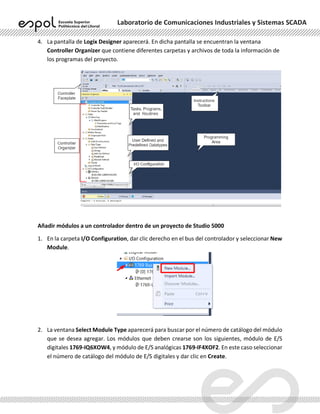
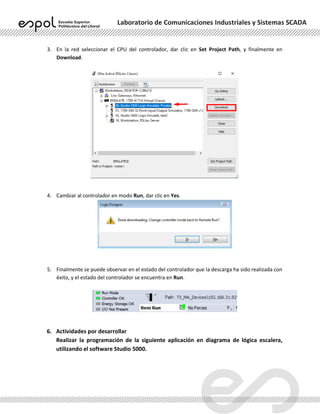
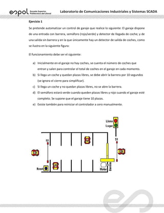


The document outlines a laboratory practice focused on using Studio 5000 Logix Designer software for programming the CompactLogix L33 PLC. It details objectives, required equipment, theoretical framework, and step-by-step procedures for creating projects and programming in Ladder Logic. The practice includes automating a garage control system that manages vehicle entry and exit based on available parking spaces.


