SlideShare a Scribd company logo
1
PS3AFET: Chapter 9 Tutorial Exercises 2013
12. Two blocks are placed at the ends of a
horizontal massless board, as in the drawing. The
board is kept from rotating and rests on a support
that serves as an axis of rotation. The moment of
inertia of this system relative to the axis is 12 kg.m2
.
Determine the magnitude of the angular
acceleration when the system is allowed to rotate.
*(27) 26. A wrecking ball (weight =4800 N) is
supported by a boom, which may be assumed to be
uniform and has a weight of 3600 N. As the drawing
shows, a support cable runs from the top of the
boom to the tractor. The angle between the
support cable and the horizontal is 320
, and the
angle between the boom and the horizontal is 480
Find (a) the tension in the support cable and
(b) the magnitude of the force exerted on the lower
end of the boom by the hinge at point P.
75
2
Solutions
12. Magnitude  of the angular acceleration = 1.3 rad/s
2
27. REASONING If we assume that the system is in equilibrium, we know that the vector sum of all
the forces, as well as the vector sum of all the torques, that act on the system must be zero.
The figure below shows a free body diagram for the boom. Since the boom is assumed to be
uniform, its weight BW is located at its center of gravity, which coincides with its geometrical
center. There is a tension T in the cable that acts at an angle  to the horizontal, as shown. At
the hinge pin P, there are two forces acting. The vertical force V that acts on the end of the
boom prevents the boom from falling down. The horizontal force H that also acts at the hinge
pin prevents the boom from sliding to the left. The weight LW of the wrecking ball (the
"load") acts at the end of the boom.
By applying the equilibrium conditions to the boom, we can determine the desired forces.
SOLUTION The directions upward and to the right will be taken as the positive directions. In
the x direction we have
cos 0xF H T    (1)
while in the y direction we have
L Bsin 0yF V T W W     (2)
Equations (1) and (2) give us two equations in three unknown. We must, therefore, find a third
equation that can be used to determine one of the unknowns. We can get the third equation
from the torque equation.
In order to write the torque equation, we must first pick an axis of rotation and determine the
lever arms for the forces involved. Since both V and H are unknown, we can eliminate them
from the torque equation by picking the rotation axis through the point P (then both V and H
have zero lever arms). If we let the boom have a length L, then the lever arm for LW is
3
cosL  , while the lever arm for BW is( /2)cosL  . From the figure, we see that the lever
arm for T is sin( – )L   . If we take counterclockwise torques as positive, then the torque
equation is
 B L
cos
cos sin 0
2
L
W W L TL

   
 
       
 
Solving for T, we have
1
B L2
cos
sin( – )
W W
T 
 

 (3)
a. From Equation (3) the tension in the support cable is
1
42
(3600 N) 4800 N
cos 48 1.6 10 N
sin(48 – 32 )
T

   
 
b. The force exerted on the lower end of the hinge at the point P is the vector sum of the forces
H and V. According to Equation (1),
 4 4
cos 1.6 10 N cos 32 1.4 10 NH T      
and, from Equation (2)
 4 4
sin 4800 N 3600 N 1.6 10 N sin 32 1.7 10 NL BV W W T          
Since the forces H and V are at right angles to each other, the magnitude of their vector sum
can be found from the Pythagorean theorem:
2 2 4 2 4 2 4
P (1.4 10 N) (1.7 10 N) 2.2 10 NF H V       
45. REASONING The angular acceleration of the bicycle wheel can be calculated from Equation 8.4.
Once the angular acceleration is known, Equation 9.7 can be used to find the net torque caused by
the brake pads. The normal force can be calculated from the torque using Equation 9.1.
SOLUTION The angular acceleration of the wheel is, according to Equation 8.4,
20 3.7 rad/s 13.1 rad/s
3.1 rad/s
3.0 st
 

 
   
If we assume that all the mass of the wheel is concentrated in the rim, we may treat the wheel
as a hollow cylinder. From Table 9.1, we know that the moment of inertia of a hollow cylinder
of mass m and radius r about an axis through its center is
2
I mr . The net torque that acts on
the wheel due to the brake pads is, therefore,
2
( )I mr    (1)
4
From Equation 9.1, the net torque that acts on the wheel due to the action of the two brake
pads is
k–2 f   (2)
where fk is the kinetic frictional force applied to the wheel by each brake pad, and 0.33 m
is the lever arm between the axle of the wheel and the brake pad (see the drawing in the text).
The factor of 2 accounts for the fact that there are two brake pads. The minus sign arises
because the net torque must have the same sign as the angular acceleration. The kinetic
frictional force can be written as (see Equation 4.8)
k k Nf F (3)
where k is the coefficient of kinetic friction and FN is the magnitude of the normal force
applied to the wheel by each brake pad.
Combining Equations (1), (2), and (3) gives
2
k N–2( ) ( )F mr 
2 2 2
N
k
– –(1.3 kg)(0.33 m) (–3.1 rad/s )
0.78 N
2 2(0.85)(0.33 m)
mr
F


  

52. REASONING Each blade can be approximated as a thin rod rotating about an axis
perpendicular to the rod and passing through one end. The moment of inertia of a blade
is given in Table 9.1 as 21
3
ML , where M is the mass of the blade and L is its length. The
total moment of inertia I of the two blades is just twice that of a single blade. The
rotational kinetic energy KER of the blades is given by Equation 9.9 as 21
R 2
KE I ,
where  is the angular speed of the blades.

 SOLUTION
a. The total moment of inertia of the two blades is
  22 2 2 21 1 2 2
3 3 3 3
265 kg 6.7 m 7900 kg mI ML ML ML     
b. The rotational kinetic energy is
  22 2 71 1
R 2 2
KE 7900 kg m 55 rad/s 1.2 10 JI    
57. REASONING AND SOLUTION The conservation of energy gives
mgh + (1/2) mv
2
+ (1/2) I
2
= (1/2) mv0
2
+ (1/2) I0
2
5
If the ball rolls without slipping,  = v/R and 0 = v0/R. We also know that I = (2/5) mR
2
.
Substitution of the last two equations into the first and rearrangement gives
    22 210 10
0 7 7
3.50 m/s 9.80 m/s 0.760 m 1.3 m/sv v gh    
58. REASONING We first find the speed 0v of the ball when it becomes airborne using the
conservation of mechanical energy. Once 0v is known, we can use the equations of kinematics
to find its range x.
SOLUTION When the tennis ball starts from rest, its total mechanical energy is in the form of
gravitational potential energy. The gravitational potential energy is equal to mgh if we take h =
0 m at the height where the ball becomes airborne. Just before the ball becomes airborne, its
mechanical energy is in the form of rotational kinetic energy and translational kinetic energy. At
this instant its total energy is 2 21 1
02 2
mv I . If we treat the tennis ball as a thin-walled
spherical shell of mass m and radius r, and take into account that the ball rolls down the hill
without slipping, its total kinetic energy can be written as
2
1 1 1 1 2 52 2 2 2 20
0 0 02 2 2 2 3 6
( )
v
mv I mv mr mv
r

 
    
 
Therefore, from conservation of mechanical energy, he have
5 2
0 06
6
or
5
gh
mgh mv v 
The range of the tennis ball is given by 0 0(cos )xx v t v t  , where t is the flight time of the
ball. From Equation 3.3b, we find that the flight time t is given by
0 0 0 0
( ) 2 sin
–
y y y
y y y
v v v v v
t
a a a
  
  
Therefore, the range of the tennis ball is
0
0 0
2 sin
(cos ) –x
y
v
x v t v
a


 
  
 
 
If we take upward as the positive direction, then using the fact that –ya g and the
expression for 0v given above, we find
2
2
0
2cos sin 2cos sin 6 12
cos sin
5 5
12
(1.8 m) (cos 35 )(sin 35 )= 2.0 m
5
gh
x v h
g g
   
 
    
        
     
  
6
75. REASONING The arm, being stationary, is in equilibrium, since it has no translational or angular
acceleration. Therefore, the net external force and the net external torque acting on the arm are
zero. Using the fact that the net external torque is zero will allow us to determine the magnitude of
the force M. The drawing at the right shows three forces: M, the 47-N weight of the arm acting at
the arm’s center of gravity (cg), and the 98-N force that acts upward on the right end of the arm.
The 98-N force is applied to the arm by the ring. It is the reaction force that arises in response to the
arm pulling downward on the ring. Its magnitude is 98 N, because it supports the 98-N weight
hanging from the pulley system. Other forces also act on the arm at the shoulder joint, but we can
ignore them. The reason is that their lines of action pass directly through the axis at the shoulder
joint, which is the axis that we will use to determine torques. Thus, these forces have zero lever
arms and contribute no torque.
SOLUTION The magnitude of each individual torque is the magnitude of the force times the
corresponding lever arm. The forces and their lever arms are as follows:
Force Lever Arm
98 N 0.61 m
47 N 0.28
M (0.069 m) sin 29
Each torque is positive if it causes a counter-clockwise rotation and negative if it causes a
clockwise rotation about the axis. Thus, since the net torque must be zero, we see that
       98 N 0.61 m 47 N 0.28 m 0.069 m sin29 0M      
Solving for M gives
     
 
98 N 0.61 m 47 N 0.28 m
1400 N
0.069 m sin 29
M

 

98 N
47 N
M
0.61 m
0.28 m
0.069 m
29
(0.070 m) sin 29
cg
Axis

More Related Content

Similar to Chapter 9 tutorial exercises with solutions 19 02 2013

Damped and undamped motion differential equations.pptx
Damped and undamped motion differential equations.pptxDamped and undamped motion differential equations.pptx
Damped and undamped motion differential equations.pptx
BrijeshMishra525980
 
v2chap2.pdf
v2chap2.pdfv2chap2.pdf
v2chap2.pdf
RicardoGulapa1
 
2nd codition of equilibrium
2nd codition of equilibrium2nd codition of equilibrium
2nd codition of equilibriumNestor Enriquez
 
Simple harmonic motion and elasticity
Simple harmonic motion and elasticitySimple harmonic motion and elasticity
Simple harmonic motion and elasticity
Menelisi Mthethwa
 
Ch09 ssm
Ch09 ssmCh09 ssm
Ch09 ssm
Marta Díaz
 
Ce 255 handout
Ce 255 handoutCe 255 handout
Ce 255 handout
DanielAkorful
 
Chapter 9
Chapter 9Chapter 9
Chapter 9
Younes Sina
 
FEM 8 Dynamic Considerations.ppt
FEM 8  Dynamic Considerations.pptFEM 8  Dynamic Considerations.ppt
FEM 8 Dynamic Considerations.ppt
Praveen Kumar
 
moment of inertia
moment of inertiamoment of inertia
moment of inertia
Evans Marshall
 
Belt Drives_2.pdf
Belt Drives_2.pdfBelt Drives_2.pdf
Belt Drives_2.pdf
HarikumarA4
 
Mm210(5a)
Mm210(5a)Mm210(5a)
Mm210(5a)
Osman Atalay
 
Physics Equilibrium
Physics EquilibriumPhysics Equilibrium
Physics Equilibrium
wehaa
 
Stresses and strains (Part 1)
Stresses and strains (Part 1)Stresses and strains (Part 1)
Stresses and strains (Part 1)
AMIE(I) Study Circle
 
7. Springs In Series And Parallel K 1 K
7. Springs In Series And Parallel K 1 K7. Springs In Series And Parallel K 1 K
7. Springs In Series And Parallel K 1 K
Richard Hogue
 
STRENGTH OF MATERIALS for beginners
STRENGTH OF MATERIALS for  beginnersSTRENGTH OF MATERIALS for  beginners
STRENGTH OF MATERIALS for beginners
musadoto
 
C10 equilibrium
C10 equilibriumC10 equilibrium
C10 equilibriumrjfurlan
 

Similar to Chapter 9 tutorial exercises with solutions 19 02 2013 (20)

Ch9
Ch9Ch9
Ch9
 
Damped and undamped motion differential equations.pptx
Damped and undamped motion differential equations.pptxDamped and undamped motion differential equations.pptx
Damped and undamped motion differential equations.pptx
 
v2chap2.pdf
v2chap2.pdfv2chap2.pdf
v2chap2.pdf
 
2nd codition of equilibrium
2nd codition of equilibrium2nd codition of equilibrium
2nd codition of equilibrium
 
Problem and solution i ph o 22
Problem and solution i ph o 22Problem and solution i ph o 22
Problem and solution i ph o 22
 
Simple harmonic motion and elasticity
Simple harmonic motion and elasticitySimple harmonic motion and elasticity
Simple harmonic motion and elasticity
 
Ch09 ssm
Ch09 ssmCh09 ssm
Ch09 ssm
 
Ce 255 handout
Ce 255 handoutCe 255 handout
Ce 255 handout
 
Chapter 9
Chapter 9Chapter 9
Chapter 9
 
FEM 8 Dynamic Considerations.ppt
FEM 8  Dynamic Considerations.pptFEM 8  Dynamic Considerations.ppt
FEM 8 Dynamic Considerations.ppt
 
moment of inertia
moment of inertiamoment of inertia
moment of inertia
 
Belt Drives_2.pdf
Belt Drives_2.pdfBelt Drives_2.pdf
Belt Drives_2.pdf
 
Gr
GrGr
Gr
 
Mm210(5a)
Mm210(5a)Mm210(5a)
Mm210(5a)
 
Physics Equilibrium
Physics EquilibriumPhysics Equilibrium
Physics Equilibrium
 
Stresses and strains (Part 1)
Stresses and strains (Part 1)Stresses and strains (Part 1)
Stresses and strains (Part 1)
 
7. Springs In Series And Parallel K 1 K
7. Springs In Series And Parallel K 1 K7. Springs In Series And Parallel K 1 K
7. Springs In Series And Parallel K 1 K
 
STRENGTH OF MATERIALS for beginners
STRENGTH OF MATERIALS for  beginnersSTRENGTH OF MATERIALS for  beginners
STRENGTH OF MATERIALS for beginners
 
C10 equilibrium
C10 equilibriumC10 equilibrium
C10 equilibrium
 
Wang1998
Wang1998Wang1998
Wang1998
 

Chapter 9 tutorial exercises with solutions 19 02 2013

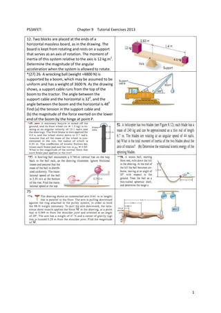
  • 1. 1 PS3AFET: Chapter 9 Tutorial Exercises 2013 12. Two blocks are placed at the ends of a horizontal massless board, as in the drawing. The board is kept from rotating and rests on a support that serves as an axis of rotation. The moment of inertia of this system relative to the axis is 12 kg.m2 . Determine the magnitude of the angular acceleration when the system is allowed to rotate. *(27) 26. A wrecking ball (weight =4800 N) is supported by a boom, which may be assumed to be uniform and has a weight of 3600 N. As the drawing shows, a support cable runs from the top of the boom to the tractor. The angle between the support cable and the horizontal is 320 , and the angle between the boom and the horizontal is 480 Find (a) the tension in the support cable and (b) the magnitude of the force exerted on the lower end of the boom by the hinge at point P. 75
  • 2. 2 Solutions 12. Magnitude  of the angular acceleration = 1.3 rad/s 2 27. REASONING If we assume that the system is in equilibrium, we know that the vector sum of all the forces, as well as the vector sum of all the torques, that act on the system must be zero. The figure below shows a free body diagram for the boom. Since the boom is assumed to be uniform, its weight BW is located at its center of gravity, which coincides with its geometrical center. There is a tension T in the cable that acts at an angle  to the horizontal, as shown. At the hinge pin P, there are two forces acting. The vertical force V that acts on the end of the boom prevents the boom from falling down. The horizontal force H that also acts at the hinge pin prevents the boom from sliding to the left. The weight LW of the wrecking ball (the "load") acts at the end of the boom. By applying the equilibrium conditions to the boom, we can determine the desired forces. SOLUTION The directions upward and to the right will be taken as the positive directions. In the x direction we have cos 0xF H T    (1) while in the y direction we have L Bsin 0yF V T W W     (2) Equations (1) and (2) give us two equations in three unknown. We must, therefore, find a third equation that can be used to determine one of the unknowns. We can get the third equation from the torque equation. In order to write the torque equation, we must first pick an axis of rotation and determine the lever arms for the forces involved. Since both V and H are unknown, we can eliminate them from the torque equation by picking the rotation axis through the point P (then both V and H have zero lever arms). If we let the boom have a length L, then the lever arm for LW is
  • 3. 3 cosL  , while the lever arm for BW is( /2)cosL  . From the figure, we see that the lever arm for T is sin( – )L   . If we take counterclockwise torques as positive, then the torque equation is  B L cos cos sin 0 2 L W W L TL                  Solving for T, we have 1 B L2 cos sin( – ) W W T      (3) a. From Equation (3) the tension in the support cable is 1 42 (3600 N) 4800 N cos 48 1.6 10 N sin(48 – 32 ) T        b. The force exerted on the lower end of the hinge at the point P is the vector sum of the forces H and V. According to Equation (1),  4 4 cos 1.6 10 N cos 32 1.4 10 NH T       and, from Equation (2)  4 4 sin 4800 N 3600 N 1.6 10 N sin 32 1.7 10 NL BV W W T           Since the forces H and V are at right angles to each other, the magnitude of their vector sum can be found from the Pythagorean theorem: 2 2 4 2 4 2 4 P (1.4 10 N) (1.7 10 N) 2.2 10 NF H V        45. REASONING The angular acceleration of the bicycle wheel can be calculated from Equation 8.4. Once the angular acceleration is known, Equation 9.7 can be used to find the net torque caused by the brake pads. The normal force can be calculated from the torque using Equation 9.1. SOLUTION The angular acceleration of the wheel is, according to Equation 8.4, 20 3.7 rad/s 13.1 rad/s 3.1 rad/s 3.0 st          If we assume that all the mass of the wheel is concentrated in the rim, we may treat the wheel as a hollow cylinder. From Table 9.1, we know that the moment of inertia of a hollow cylinder of mass m and radius r about an axis through its center is 2 I mr . The net torque that acts on the wheel due to the brake pads is, therefore, 2 ( )I mr    (1)
  • 4. 4 From Equation 9.1, the net torque that acts on the wheel due to the action of the two brake pads is k–2 f   (2) where fk is the kinetic frictional force applied to the wheel by each brake pad, and 0.33 m is the lever arm between the axle of the wheel and the brake pad (see the drawing in the text). The factor of 2 accounts for the fact that there are two brake pads. The minus sign arises because the net torque must have the same sign as the angular acceleration. The kinetic frictional force can be written as (see Equation 4.8) k k Nf F (3) where k is the coefficient of kinetic friction and FN is the magnitude of the normal force applied to the wheel by each brake pad. Combining Equations (1), (2), and (3) gives 2 k N–2( ) ( )F mr  2 2 2 N k – –(1.3 kg)(0.33 m) (–3.1 rad/s ) 0.78 N 2 2(0.85)(0.33 m) mr F       52. REASONING Each blade can be approximated as a thin rod rotating about an axis perpendicular to the rod and passing through one end. The moment of inertia of a blade is given in Table 9.1 as 21 3 ML , where M is the mass of the blade and L is its length. The total moment of inertia I of the two blades is just twice that of a single blade. The rotational kinetic energy KER of the blades is given by Equation 9.9 as 21 R 2 KE I , where  is the angular speed of the blades.   SOLUTION a. The total moment of inertia of the two blades is   22 2 2 21 1 2 2 3 3 3 3 265 kg 6.7 m 7900 kg mI ML ML ML      b. The rotational kinetic energy is   22 2 71 1 R 2 2 KE 7900 kg m 55 rad/s 1.2 10 JI     57. REASONING AND SOLUTION The conservation of energy gives mgh + (1/2) mv 2 + (1/2) I 2 = (1/2) mv0 2 + (1/2) I0 2
  • 5. 5 If the ball rolls without slipping,  = v/R and 0 = v0/R. We also know that I = (2/5) mR 2 . Substitution of the last two equations into the first and rearrangement gives     22 210 10 0 7 7 3.50 m/s 9.80 m/s 0.760 m 1.3 m/sv v gh     58. REASONING We first find the speed 0v of the ball when it becomes airborne using the conservation of mechanical energy. Once 0v is known, we can use the equations of kinematics to find its range x. SOLUTION When the tennis ball starts from rest, its total mechanical energy is in the form of gravitational potential energy. The gravitational potential energy is equal to mgh if we take h = 0 m at the height where the ball becomes airborne. Just before the ball becomes airborne, its mechanical energy is in the form of rotational kinetic energy and translational kinetic energy. At this instant its total energy is 2 21 1 02 2 mv I . If we treat the tennis ball as a thin-walled spherical shell of mass m and radius r, and take into account that the ball rolls down the hill without slipping, its total kinetic energy can be written as 2 1 1 1 1 2 52 2 2 2 20 0 0 02 2 2 2 3 6 ( ) v mv I mv mr mv r           Therefore, from conservation of mechanical energy, he have 5 2 0 06 6 or 5 gh mgh mv v  The range of the tennis ball is given by 0 0(cos )xx v t v t  , where t is the flight time of the ball. From Equation 3.3b, we find that the flight time t is given by 0 0 0 0 ( ) 2 sin – y y y y y y v v v v v t a a a       Therefore, the range of the tennis ball is 0 0 0 2 sin (cos ) –x y v x v t v a            If we take upward as the positive direction, then using the fact that –ya g and the expression for 0v given above, we find 2 2 0 2cos sin 2cos sin 6 12 cos sin 5 5 12 (1.8 m) (cos 35 )(sin 35 )= 2.0 m 5 gh x v h g g                             
  • 6. 6 75. REASONING The arm, being stationary, is in equilibrium, since it has no translational or angular acceleration. Therefore, the net external force and the net external torque acting on the arm are zero. Using the fact that the net external torque is zero will allow us to determine the magnitude of the force M. The drawing at the right shows three forces: M, the 47-N weight of the arm acting at the arm’s center of gravity (cg), and the 98-N force that acts upward on the right end of the arm. The 98-N force is applied to the arm by the ring. It is the reaction force that arises in response to the arm pulling downward on the ring. Its magnitude is 98 N, because it supports the 98-N weight hanging from the pulley system. Other forces also act on the arm at the shoulder joint, but we can ignore them. The reason is that their lines of action pass directly through the axis at the shoulder joint, which is the axis that we will use to determine torques. Thus, these forces have zero lever arms and contribute no torque. SOLUTION The magnitude of each individual torque is the magnitude of the force times the corresponding lever arm. The forces and their lever arms are as follows: Force Lever Arm 98 N 0.61 m 47 N 0.28 M (0.069 m) sin 29 Each torque is positive if it causes a counter-clockwise rotation and negative if it causes a clockwise rotation about the axis. Thus, since the net torque must be zero, we see that        98 N 0.61 m 47 N 0.28 m 0.069 m sin29 0M       Solving for M gives         98 N 0.61 m 47 N 0.28 m 1400 N 0.069 m sin 29 M     98 N 47 N M 0.61 m 0.28 m 0.069 m 29 (0.070 m) sin 29 cg Axis