
Download to read offline
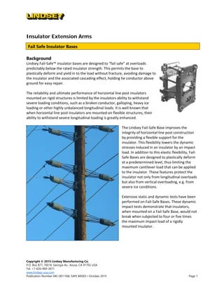
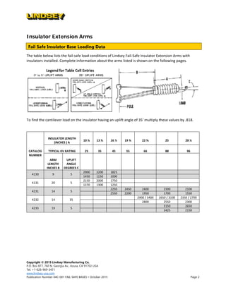


Lindsey Manufacturing's fail-safe insulator bases are designed to prevent damage during overload conditions by deforming plastically rather than breaking, thus enhancing the reliability of insulator systems amidst severe loading situations. The document details the performance characteristics, loading data, and available models of these insulator bases and extension arms. Additional accessories for installation, including pole brackets and pot head adapters, are also described.


