GROUP PROJECT
Fabiha ShumaimB21108006007
M. Meraj ul Qadar Ansari B21108006016
Rafia Hameed B21108006023
Course: Chemical Engineering & Plant Design (CE-
607)
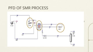
PFD OF SMRPROCESS
Mercury is the closest planet to the Sun and the smallest one in the Solar System—it’s
only a bit larger than the Moon. The planet’s name has nothing to do with the liquid metal
Venus has a beautiful name and is the second planet from the Sun. It’s terribly hot—even
hotter than Mercury—and its atmosphere is extremely poisonous
Jupiter is a gas giant and the biggest planet in the Solar System. It's the fourth-brightest
object in the night sky. It was named after the Roman god of the skies and lightning
What about Mercury?
What about Venus?
What about Jupiter?
01
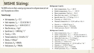
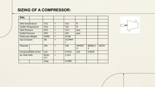
SIZING OF ACOMPRESSOR:
Data
Inlet temperature (T1) = 513 R
Outlet Temperature (T2) = 735 R
Inlet Pressure (P1) = 72.5 psia
Outlet Pressure (P2) = 435 psia
Molecular Weight (MW) = 29.08
Gas Constant (R) = 53.0949
1
Flowrate (W) = 530 MMSCF
D
68586.6
3
ACFM
Compressibility factor (z1) = 0.9331 (z2) 0.9639
sp. Heat ratio K(Cp/
Cv)
= 1.214
Zavg 0.9485
13.
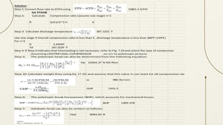
Solution
Step 1: Convertflow rate to ICFM using 12801.5 ICFM
1st STAGE
Step 2: Calculate Compression ratio (assume one stage) n=1
R (p2/p1)^1/n 6
Step 3: Calculate discharge temperature, T2, 307.1252 ˚F
Use one stage if Overall compression ratio is less than 5 ,Suction gas temperature is under 110°F (43°C)
, discharge temperature is less than 300°F (149°C)
For n=2
R 2.44949
Td 167.3239 ˚F
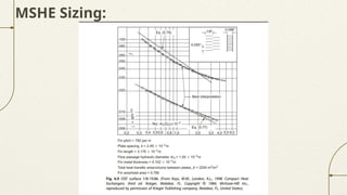
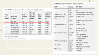
Step 4: If Step 4 indicates that intercooling is not necessary, refer to Fig. 7.24 and select the type of compressor.
Assuming CENTRIFUGAL COMPRESSOR ,so a/c to polytropic process
Step 4: The polytropic head can also be determined from the following equation:
Hp 52404.37 ft lbf/lbm
Step 10: Calculate weight flow using Eq. (7.15) and assume that this value is con stant for all compression steps
w 980 lb/min
GHP 1945.3
Step 6: The polytropic break horsepower (BHP), which accounts for mechanical losses
BHP 1309.378
Step 7: Adiabatic head can also be written as follows:
Had 8583.65 ft
14.
Outlet Temperature (T2)= 735 R
Inlet Pressure (P1) = 172.2963 psia
Outlet Pressure (P2) = 435 psia
Molecular Weight (MW) = 29.08
Gas Constant (R) = 53.09491
Flowrate (W) = 530 MMSCFD 35290.64 ACFM 28167.12 lb/min
Compressibilty factor (z1) = 0.9331 (z2) 0.9639 zavg 0.9485
sp. Heat ratio K(Cp/Cv) = 1.219
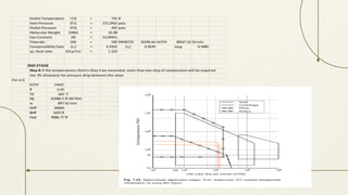
2ND STAGE
Step 6: If the temperatures cited in Step 4 are exceeded, more than one step of compression will be required
Use 3% allowance for pressure drop between the steps
For n=2
ICFM 13421
R 2.45
Td 263 ˚F
Hp 61006.5 ft lbf/lbm
w 897 lb/min
GHP 20600
BHP 1437.8
Had 9086.77 ft
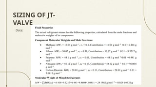
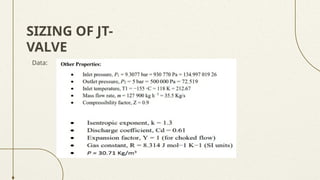
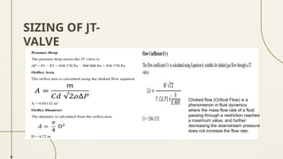
SIZING OF JT-
VALVE
Chokedflow (Critical Flow) is a
phenomenon in fluid dynamics
where the mass flow rate of a fluid
passing through a restriction reaches
a maximum value, and further
decreasing the downstream pressure
does not increase the flow rate.
References:
• J. E.Hesselgreaves, R. Law, and D. A. Reay, Compact Heat Exchangers: Selection,
Design and Operation, 2nd ed. Amsterdam: Elsevier, 2017. doi: 10.1016/B978-0-08-
100305-3.00001-X.
• R. K. Shah and D. P. Sekulic, Fundamentals of Heat Exchanger Design. Hoboken, NJ,
USA: Wiley, 2003.
• M. Stewart, Surface Production Operations: Pumps and Compressors, Volume IV.
Cambridge, MA, USA: Gulf Professional Publishing, an imprint of Elsevier, 2019.
ISBN: 978-0-12-809895-0.
• Crane Co. (2018). Flow of Fluids Through Valves, Fittings, and Pipe (Technical Paper
No. 410, 30th Edition). Crane Co.
• nternational Society of Automation. ISA Handbook of Control Valves. 2nd ed., edited
by William W. Edstrom, Jr., ISA—The Instrumentation, Systems, and Automation
Society, 2014.