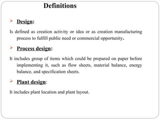
Definitions
Design:
Is definedas creation activity or idea or as creation manufacturing
process to fulfill public need or commercial opportunity.
Process design:
It includes group of items which could be prepared on paper before
implementing it, such as flow sheets, material balance, energy
balance, and specification sheets.
Plant design:
It includes plant location and plant layout.
3.
Aim of Chemical
EngineeringDesign
Construction of new chemical plants.
Expansion or revision of existing plants in order to
increase the productivity.
Modification of existing plant in order to change the
product or the way of production.
4.
Practical considerations
in design
Thechemical engineer must never lose sight of the
practical limitations involved in a design.
It may be possible to determine an exact pipe diameter for an
optimum economic design, but this does not mean that this exact
size must be used in the final design.
Suppose the optimum diameter were, 3.43 in. (8.71 cm). It would be
impractical to have a special pipe fabricated with an inside diameter
of 3.43 in. Instead, the engineer would choose a standard pipe size
which could be purchased at regular market prices. In this case, the
recommended pipe size would probably be a standard 3 in.-diameter
pipe having an inside diameter of 3.55 in. (9.02 cm).
5.
Practical considerations
in design
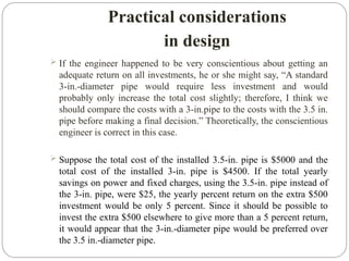
If the engineer happened to be very conscientious about getting an
adequate return on all investments, he or she might say, “A standard
3-in.-diameter pipe would require less investment and would
probably only increase the total cost slightly; therefore, I think we
should compare the costs with a 3-in.pipe to the costs with the 3.5 in.
pipe before making a final decision.” Theoretically, the conscientious
engineer is correct in this case.
Suppose the total cost of the installed 3.5-in. pipe is $5000 and the
total cost of the installed 3-in. pipe is $4500. If the total yearly
savings on power and fixed charges, using the 3.5-in. pipe instead of
the 3-in. pipe, were $25, the yearly percent return on the extra $500
investment would be only 5 percent. Since it should be possible to
invest the extra $500 elsewhere to give more than a 5 percent return,
it would appear that the 3-in.-diameter pipe would be preferred over
the 3.5 in.-diameter pipe.
6.
Practical considerations
in design
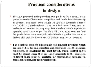
The logic presented in the preceding example is perfectly sound. It is a
typical example of investment comparison and should be understood by
all chemical engineers. Even though the optimum economic diameter
was 3.43 in., the good engineer knows that this diameter is only an exact
mathematical number and may vary from month to month as prices or
operating conditions change. Therefore, all one expects to obtain from
this particular optimum economic calculation is a good estimation as to
the best diameter, and investment comparisons may not be necessary.
The practical engineer understands the physical problems which
are involved in the final operation and maintenance of the designed
equipment. In developing the plant layout, crucial control valves
must be placed where they are easily accessible to the operators.
Sufficient space must be available for maintenance personnel to
check, take apart, and repair equipment.
7.
Practical considerations
in design
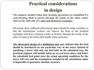
The engineer should realize that cleaning operations are simplified if a
scale-forming fluid is passed through the inside of the tubes rather
than on the shell side of a tube-and-shell heat exchanger.
Obviously, then, sufficient plant-layout space should be made available so
that the maintenance workers can remove the head of the installed
exchanger and force cleaning worms or brushes through the inside of the
tubes or remove the entire tube bundle when necessary.
The theoretical design of a distillation unit may indicate that the feed
should be introduced on one particular tray in the tower. Instead of
specifying a tower with only one feed inlet on the calculated tray, the
practical engineer will include inlets on several trays above and below
the calculated feed point since the actual operating conditions for the
tower will vary and the assumptions included in the calculations make
it impossible to guarantee absolute accuracy.
8.
Practical considerations
in design
Thepreceding examples typify the type of
practical problems the chemical engineer
encounters.
Thus in design work, theoretical and economic
principles must be combined with an
understanding of the common practical problems
that will arise when the process finally comes to
life in the form of a complete plant or a complete
unit.
9.
Process design
development
1. TYPESOF DESIGNS:
The methods for carrying out a design project may be
divided into the following classifications, depending on
the accuracy and detail required:
1. Preliminary or quick-estimate designs.
2. Detailed-estimate designs.
3. Firm process designs or detailed designs.
10.
Process design
development
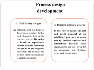
1. Preliminarydesigns
are ordinarily used as a basis for
determining whether further
work should be done on the
proposed process. The design
is based on approximate
process methods, and rough
cost estimates are prepared.
Few details are included, and
the time spent on calculations
is kept at a minimum.
2. Detailed-estimate design:
In this type of design, the cost
and profit potential of an
established process is determi-
ned by detailed analyses and
calculations. However, exact
specifications are not given for
the equipment, and drafting-
room work is minimized.
11.
Process design
development
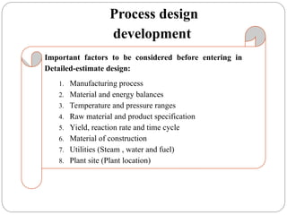
Important factorsto be considered before entering in
Detailed-estimate design:
1. Manufacturing process
2. Material and energy balances
3. Temperature and pressure ranges
4. Raw material and product specification
5. Yield, reaction rate and time cycle
6. Material of construction
7. Utilities (Steam , water and fuel)
8. Plant site (Plant location)
12.
Process design
development
3. Firmprocess design:
is the final step before developing
construction plans for the plant. It
is characterized with complete
specifications for all components
of the plant, accurate costs based
on quoted prices are obtained,
blueprints and sufficient informa-
tion to permit immediate develop-
ment of the final plans for cons-
tructing the plant, and complete
flow sheet is presented.
13.
Feasibility survey
Beforeany detailed work is done on the design, the technical and
economic factors of the proposed process should be examined.
The various reactions and physical processes involved must be
considered, along with the existing and potential market conditions for
the particular product.
A preliminary survey of this type gives an indication of the probable
success of the project and also shows what additional information is
necessary to make a complete evaluation.
14.
Following is alist of items that should be considered in making a
feasibility survey:
1. Raw materials (availability, quantity, quality, cost)
2.Thermodynamics and kinetics of chemical reactions involved
(equilibrium, yields, rates, optimum conditions)
3. Facilities and equipment available at present
4. Facilities and equipment which must be purchased
5. Estimation of production costs and total investment
6. Profits (probable and optimum, per pound of product and per year, return
on investment)
7. Materials of construction.
8. Safety considerations.
9. Markets (present and future supply and demand, present uses, new uses,
present buying habits, price range for products and by-products, character,
location, and number of possible customers)
15.
Following is alist of items that should be considered in making a
feasibility survey:
10. Competition (overall production statistics, comparison of various
manufacturing processes, product specifications of competitors)
11. Properties of products (chemical and physical properties, specifications,
impurities, effects of storage).
12. Sales and sales service (method of selling and distributing, advertising
required, technical services required).
13. Shipping restrictions and containers.
14. Plant location.
15. Patent situation and legal restrictions.
16.
Flow diagrams
Thechemical engineer uses flow diagrams
to show the sequence of equipment and unit operations in the overall process,
to simplify visualization of the manufacturing procedures, and
to indicate the quantities of materials and energy transfer.
These diagrams may be divided into three general types: (1) qualitative,
(2) quantitative, and (3) combined-detail.
A qualitative flow diagram indicates the flow of materials, unit operations
involved, equipment necessary, and special information on operating
temperatures and pressures.
A quantitative flow diagram shows the quantities of materials required for
the process operation. An example of a qualitative flow diagram is shown in
the following figure:
17.
[Qualitative process flowdiagram for the manufacture of nitric acid by the
ammonia-oxidation process].
18.
An example ofa quantitative flow diagram is shown in the following figure:
[Quantitative process flow diagram for the manufacture of nitric acid by the ammonia-
oxidation process].
19.
An example ofa combined flow diagram is shown in the following figure:
[Combined flow diagram for the manufacture of nitric acid by the ammonia-
oxidation process].
20.
The flowsheet importance
Showsthe arrangement of the equipment selected to carry
out the process.
Shows the streams concentrations, flow rates &
compositions.
Shows the operating conditions.
During plant start up and subsequent operation, the flow
sheet act as a basis for comparison of operating performance
with design. It is also used by operating personnel for the
preparation of operating manual and operator training.
21.
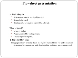
Flowsheet presentation
1- Blockdiagram
Represent the process in a simplified form.
No details involved.
Don’t describe how a given step will be achieved.
When is it used?
In survey studies.
Process proposal for packaged steps.
Talk out a processing idea.
2- Pictorial Flow Sheet
The equipment's are normally drawn in a stylized pictorial form. For tender documents
or company brochures actual scale drawing of the equipment are sometimes used.
Types of pictorial
flowsheets
a)Process Flow Diagram (PFD)
b) Piping and Instrumentation Diagram (P & ID)
(mechanical flow diagram)
c) Utility Flowsheet (Process Engineering Utility Flow
Diagram (PEUFD))
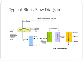
A Typical Block Flow Diagram
24.
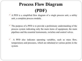
Process Flow Diagram
(PDF)
A PFD is a simplified flow diagram of a single process unit, a utility
unit, a complete process module.
The purpose of a PFD is to provide a preliminary understanding of the
process system indicating only the main items of equipment, the main
pipelines and the essential instruments, switches and control valves.
A PFD also indicates operating variables, such as mass flow,
temperatures and pressures, which are tabulated at various points in the
system.
25.
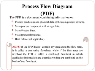
The PFD isa document containing information on:
Process conditions and physical data of the main process streams.
Main process equipment with design data.
Main Process lines.
Mass (material) balance.
Heat balance (if applicable).
NOTE: If the PFD doesn’t contain any data about the flow rates,
it is called a qualitative flowsheet, while if the flow rates are
involved the PFD is called a combined flowsheet in which
qualitative information and quantitative data are combined on the
basis of one flowsheet.
Process Flow Diagram
(PDF)
26.
Qualitative process flowdiagram (PFD) for the manufacture of nitric acid
by the ammonia-oxidation process.
27.
[Combined process flowdiagram for the manufacture of nitric acid by the
ammonia-oxidation process].
28.
Contents of ProcessFlow Diagram
(PFD)
A PFD should normally contain the following information about the plant process.
Main process equipments with reference tag numbers, name. Process
operating and design conditions are also usually provided.
Main process streams are normally provided with reference stream numbers.
It should be noted that streams are different than lines and stream numbers are not
related to line numbers in any way.The streams that normally do not have any flow
are indicated with an abbreviation NNF (Normally No Flow).
Basic process data for each stream is sometimes given in the PFD against
each stream number.This includes data such as operating temperature, pressure,
flowrates, compositions etc. for each process stream. Sometimes, this process data
is represented for each stream number, in a separate drawing known as heat and
mass balance sheet. Design conditions for a stream are not normally indicated in a
PFD.
http://www.enggcyclopedia.com/2011/01/process-flow-diagram-pfd/
“Analysis, Synthesis and Design of Chemical Processes”, Turton, 4th
Ed. 2016
29.
Important isolationvalves are also indicated in the PFD. Not all manual valves appear in
the P&ID, only a few which can improve the understanding of a process from the PFD. Some
valves are indicated as normally closed or locked closed depending on requirement.
Automatic valves - motor operated valves / emergency shutdown valves / control
valves appear on the PFD without the associated tag numbers.The purpose is better
description of process.Associated control elements are also represented very briefly on the
PFD.
Notes are added wherever required to improve the understanding of the process from PFD.
Legend is a list of symbols used on the PFD with brief explanation.This 'legend' can appear
on each sheet of PFDs or can appear on a single sheet with other sheets referring to a
'Legend Sheet'.
Interconnections from one PFD sheet to another are used for process streams and
instrument control signals to maintain continuity between different drawings.
Some items which appear on the P&ID but may not appear on the PFD are - safety valves,
detailed instruments, lines, fittings, drains vents and tag numbers for all of them.
30.
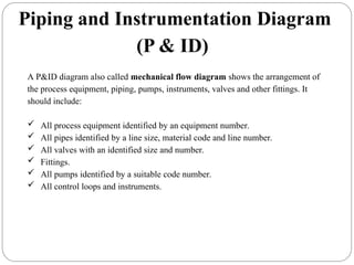
A P&ID diagramalso called mechanical flow diagram shows the arrangement of
the process equipment, piping, pumps, instruments, valves and other fittings. It
should include:
All process equipment identified by an equipment number.
All pipes identified by a line size, material code and line number.
All valves with an identified size and number.
Fittings.
All pumps identified by a suitable code number.
All control loops and instruments.
Piping and Instrumentation Diagram
(P & ID)
32.
A P&ID shouldprovide following data to piping and instrument engineers, to
construction teams and to the operators:
1.Equipment's - tanks, vessels, heat exchangers, pumps, compressors,
columns etc. have to be indicated with type, reference tag numbers, basic
design data, spares etc.
2.Lines - reference tag numbers, piping material class, line size, fluid
service, insulation type and thickness etc. Sometimes process data such as
line operating pressure, temperature and flowrates is also represented on
the P&ID lines.
3.Some other piping requirements - such as slope, special insulation such
as heat tracing, minimum / maximum piping distance requirements along
with their values are also shown on P&IDs.
4.Manually operated piping valves - valve type (ball valve, gate valve, check
valve etc.), valve size, Locked closed/open, sealed closed/open, normally
closed/open etc.
5.Piping fittings - Flanges, reducers/expanders, spectacle blinds,
spacers, strainers etc. along with their size wherever necessary.
Piping and Instrumentation Diagram
33.
6. Drains andVents - are usually indicated using typical symbols along with
their size and type (single valve, double valve etc.).
7. Automated valves - Shutdown valves (SDV), control valves, blowdown
valves (BDV) are indicated with size if it is known. Also fail position (fail
open/fail close/fail in position) is indicated for each of these
valves. Actuator connection and type is indicated. Reference instrument
tag numbers are attached to every automatic valves.
8. Safety Valves - Pressure relief valve (PRV) or Temperature relief valve
(TRV) are indicated with their instrument tag numbers, set-points, types
are indicated by different symbols.
9. Instruments - Gauges, transmitters, local indicators, DCS indicators,
interlocks and other functions have to be shown in detail on the P&ID.
Interconnection between these elements has to be indicated by different
types of instrument signals (hardwired signal, soft signal, pneumatic or
hydraulic signal etc.). The location of the instrument elements (field
mounted or DCS) is indicated by difference between symbols.
Piping and Instrumentation Diagram
(P & ID)
34.
10.Notes - arewritten wherever required to improve clarity for anyone
referring to the P&ID. Sometime 'Hold' is used to indicate uncertainty
about relevant data.
11.Interconnections (OPC) - are shown between lines (piping OPC) and
instrument signals (Instrument OPC) present on two different P&ID
sheets. Sometime these interconnectors are also assigned with a unique
tag number. For easy identification of the connections between two
P&IDs. A connector present on two different drawing connection a line or
a signal carries the same tag number.
Because of the numerous details involved in P&IDs for each equipment,
usually only one main equipment is shown on one P&ID sheet with
related instruments and piping.
Piping and Instrumentation Diagram
(P & ID)
http://www.enggcyclopedia.com/2011/01/process-flow-diagram-pfd/
Line Number Designation
Atypical line number or line designation would be as follows:
3" PV-500-40-A1-2"HC-ST
Where:
3" = Nominial diameter of the line,
PV = Service Classification,
500 = Line Number,
040 = Pipe Schedule,
A1 = ANSI Pressure Rating with material class designation,
2"HC = Coating or Insulation thickness and function
ST =Type of heat tracing to be used.
http://www.piping-designer.com/Line_Designation
38.
Control Valves –Typical P&ID
arrangement
http://www.enggcyclopedia.com/2011/01/process-flow-diagram-pfd/
39.
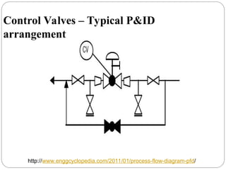
The sampledrawing presented here represents a typical arrangement generally used
to represent control valves on P&ID. Depending on the projects legend sheets, control
valves may be represented by globe or gate valves. Here a globe valve symbol is used.
First of all a proper valve symbol should be selected to represent the control valve as
per the project standards.
Generally, the control valve size is smaller than the corresponding line size.This
change in diameter should be clearly indicated in the P&ID with reducer and
expander.
Block valves should be provided upstream and downstream of the control valves in
case of shutdown and maintenance.
A drain valve is normally provided between the control valve and upstream block
valve. If the control valve is of 'Fail Open' type, this drain valve is sufficient to drain
the piping segment. If the control valve is of 'Fail Close' or 'Fail in Position' type, then
additional drain valve is required between the control valve and downstream block
valve as shown in the sample drawing.
Control Valves – Typical P&ID
arrangement
40.
Normally, eithera bypass or a handwheel is provided for control valves which
are under continuous service. If two or more control valves are installed in
parallel, bypass or handwheel is not required.
The choice between providing either a bypass or a handwheel for
the control valve is made based on the size of the control valve. For control
valves bigger than a certain size, provision of handwheel is preferred. For
control valves smaller than certain size, provision of bypass with block valves is
preferred. For control valves on certain critical services, a spare control valve
may be installed on the bypass of main control valve.This limiting control valve
size between handwheel and bypass is specific for a project and may vary from
one project to another.
Control Valves – Typical P&ID
arrangement
41.
If thecontrol valve is equipped with a handwheel, then only the drain between
control valve and upstream block valve is sufficient for draining by opening the
control valve using handwheel.
Normally globe valve is selected as the bypass valve on the control valve as it
allows better control with opening.
Additional details such as failure position, # rating etc. are also indicated on the
P&ID for control valves, as per the project standards.
Control Valves – Typical P&ID
arrangement
Typical P&ID arrangementfor Heat
Exchangers
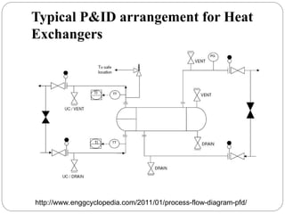
Proper equipment symbol should be selected first of all, as shown in the
presented drawing.This should be selected from the list of equipment symbols
on the legend sheets of a particular project.
All the nozzles on the exchanger should then be correctly represented with size
and flanges.This includes inlet and outlet nozzles, drains, vents, utility
connections etc.
Inlet and outlet lines are the next to be drawn up. Line number, material class,
size etc. is to be correctly assigned to each of the lines. If the unit is envisaged to
be in operation while the exchanger is under maintenance, then bypass lines
should be drawn up on shellside, tubeside or on both sides as shown in the
drawing presented here.
Isolation valves, spectacle blinds, spacers etc. to be used for maintenance should
be drawn up next on the inlet / outlet lines. Bypass lines to be fitted with
normally closed isolation valves.
44.
Typical P&ID arrangementfor Heat
Exchangers
Thermal relief valve should be provided where required. Generally thermal relief
valves are required on the cold liquid streams, when there is a possibility of blockage
in the heating medium on the other side of exchanger. In case of such blockage, there
is possibility of overheating the cold stream and hence requirement for thermal relief
valve. Discharge of a relief valve to be routed to an appropriate, safe location.
Drains and vents to be provided on both sides of the exchanger (hot and cold sides),
either on the exchanger itself or inlet / outlet piping, so that the equipment can be
completely drained for maintenance.
For fouling service on the tubeside, utility connections should be provided as
indicated in the presented drawing, for cleaning purpose.
Temperature and pressure gauges and transmitters to be provided as per
requirements for operating and controlling the equipment. Normally temperature
monitoring is required for the process side of the heat exchanger.Also generally
temperature control is implemented on the process side of the exchanger.
Typical P&ID arrangementfor pumps
Proper pump symbol should be selected first of all, as shown in the presented drawing.
This should be selected from the list of equipment symbols on the legend sheets of a
particular project.
All the nozzles on the pump should then be correctly represented with size and
flanges.This includes inlet and outlet nozzles and casing drains and vents as shown in
the sample drawing presented here. Generally, the suction and discharge nozzles on
the pump are smaller than suction and discharge line sizes.Appropriate reducer /
expander to be clearly indicated in such cases.
Inlet and outlet lines are the next to be drawn up. Line number, material class, size
etc. is to be correctly assigned to each of the lines.
Isolation valves, spectacle blinds, spacers etc. to be used for maintenance should be
drawn up next on the inlet / outlet lines.The isolation valves on suction and discharge
lines should be 'Locked Open' in case of automatic pump start-up.
Inlet line to the pump is to be fitted with a strainer for pump protection.This strainer
can be equipped with a pressure differential gauge to monitor blockage in the strainer.
47.
Typical P&ID arrangementfor pumps
Pressure gauges are normally to be provided on suction and discharge of the
pump. In addition, pressure transmitters connected to Emergency Shutdown
(ESD) system can also be provided as per requirements.
A check valve should be normally provided on the pump discharge to avoid
reverse flow when the pump is not in operation.
Downstream to the check valve on the pump discharge, minimum flow
recirculation line for the pump needs to be provided.A flowmeter should be
provided before the minimum flow line, as shown on the presented sample
drawing.
A flow control valve with or without bypass is then to be provided on the
minimum flow recirculation line.The isolation valves for this control valve need
to be locked open or sealed open and the FCV should be of 'Fail Open' type.The
minimum recirculation line is normally routed back to the suction vessel of the
pump.
48.
Typical P&ID arrangementfor pumps
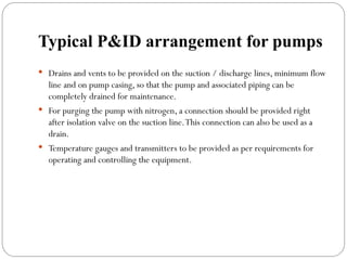
Drains and vents to be provided on the suction / discharge lines, minimum flow
line and on pump casing, so that the pump and associated piping can be
completely drained for maintenance.
For purging the pump with nitrogen, a connection should be provided right
after isolation valve on the suction line.This connection can also be used as a
drain.
Temperature gauges and transmitters to be provided as per requirements for
operating and controlling the equipment.
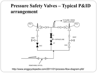
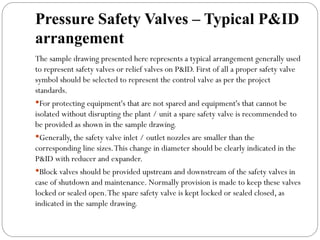
Pressure Safety Valves– Typical P&ID
arrangement
The sample drawing presented here represents a typical arrangement generally used
to represent safety valves or relief valves on P&ID. First of all a proper safety valve
symbol should be selected to represent the control valve as per the project
standards.
For protecting equipment's that are not spared and equipment's that cannot be
isolated without disrupting the plant / unit a spare safety valve is recommended to
be provided as shown in the sample drawing.
Generally, the safety valve inlet / outlet nozzles are smaller than the
corresponding line sizes.This change in diameter should be clearly indicated in the
P&ID with reducer and expander.
Block valves should be provided upstream and downstream of the safety valves in
case of shutdown and maintenance. Normally provision is made to keep these valves
locked or sealed open.The spare safety valve is kept locked or sealed closed, as
indicated in the sample drawing.
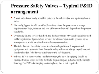
51.
Pressure Safety Valves– Typical P&ID
arrangement
A vent valve is normally provided between the safety valve and upstream block
valve.
Normally, bypass should provided for safety valves for process or start-up
requirements.Type, number and size of bypass valves will depend on the project
standards.
Depending on the service handled, the discharge from PSV can be either routed
to flare system for hydrocarbon service, for closed/open drain systems or to
atmosphere at a safe location for non-hazardous service.
The inlet lines to the safety valves are always sloped toward to protected
equipment and the outlet lines from the safety valves are always sloped towards
the flare header / the knock out drum or the safe location.
When a PSV is connected to the flare system, the inlet line piping should be
equipped with a spool piece to facilitate dismantling, as indicated in the sample
drawing. For PSVs discharging to atmosphere, this is not required.
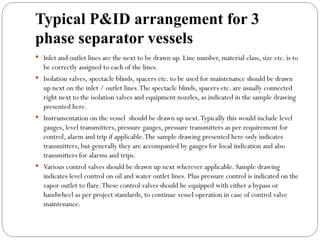
Typical P&ID arrangementfor 3
phase separator vessels
3 phase separators are commonly used in upstream oil and gas industry to separate oil,
gas and water stream coming from the oil wells.This typical P&ID arrangement can be
modified and used for other separator vessels as well.
Proper vessel symbol should be selected first of all, as shown in the presented drawing.
This should be selected from the list of equipment symbols on the legend sheets of a
particular project.
Separator vessel internals should then be indicated as per proper symbols on the legend
sheets.These internals can be inlet vane, vortex breaker on the outlet lines, demister
pads on gas outlets, weir plate separating the oil and water compartments etc.
All the nozzles on the separator vessel should then be correctly represented with size
and flanges.This includes inlet and outlet nozzles, drains, vents, PSV connection and
instrument nozzles, as shown in the sample drawing presented here.Typical
instrumentation on the vessel would be level gauges and transmitters on oil and water
compartments of the vessel plus pressure gauge and transmitters linked to pressure
control or alarms as applicable.
54.
Typical P&ID arrangementfor 3
phase separator vessels
Inlet and outlet lines are the next to be drawn up. Line number, material class, size etc. is to
be correctly assigned to each of the lines.
Isolation valves, spectacle blinds, spacers etc. to be used for maintenance should be drawn
up next on the inlet / outlet lines.The spectacle blinds, spacers etc. are usually connected
right next to the isolation valves and equipment nozzles, as indicated in the sample drawing
presented here.
Instrumentation on the vessel should be drawn up next.Typically this would include level
gauges, level transmitters, pressure gauges, pressure transmitters as per requirement for
control, alarm and trip if applicable.The sample drawing presented here only indicates
transmitters, but generally they are accompanied by gauges for local indication and also
transmitters for alarms and trips.
Various control valves should be drawn up next wherever applicable. Sample drawing
indicates level control on oil and water outlet lines. Plus pressure control is indicated on the
vapor outlet to flare.These control valves should be equipped with either a bypass or
handwheel as per project standards, to continue vessel operation in case of control valve
maintenance.
55.
Typical P&ID arrangementfor 3
phase separator vessels
Drains should be provided either on the vessel or on the bottom outlet lines for
complete draining of the vessel and associated piping for maintenance purpose.
Sample drawing has indicated drains on the outlet lines through which the vessel
and piping can be completely drained. Usually the vessel also has nozzles
connecting it directly to the draining system.
Vents can be present either on the vessel itself or on the vapor outlet line, so that
the vessel and associated piping can be completely vented for maintenance.Vent
connected directly to vessel is indicated in the sample drawing.
In most cases the vessel is provided with a blanketing gas connection.This
blanketing connection can be with or without pressure control.Although not
indicated in the sample drawing, it is important to consider the blanketing gas
connection to the vessel.
For purging the vessel with nitrogen, a connection can be provided directly on
the vessel. In some cases purging can be done with steam.
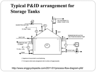
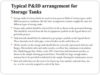
Typical P&ID arrangementfor
Storage Tanks
Storage tanks of various kinds are used to store process fluids of various types, under
different process conditions. But the basic arrangement remains roughly the same for
different types of storage tanks.
Proper tank symbol should be selected first of all, as shown in the presented drawing.
This should be selected from the list of equipment symbols on the legend sheets of a
particular project.
Tank internals should then be indicated as per proper symbols on the legend sheets.
These internals can be inlet pipe, vortex breaker on the outlet lines etc.
All the nozzles on the storage tank should then be correctly represented with size and
flanges.This includes inlet and outlet nozzles, overflow line, minimum recirculation
line, blanketing gas line, drains, vents, PSV connection and instrument nozzles, as
shown in the sample drawing presented here. Normally for large enough tanks a
manway has to be provided as indicated in the sample drawing for maintenance access.
Inlet and outlet lines are the next to be drawn up. Line number, material class, size
etc. is to be correctly assigned to each of the lines.
58.
Typical P&ID arrangementfor
Storage Tanks
Typical instrumentation on the tank would be level gauges and transmitters plus pressure gauge
and transmitters. For tank under continuous operation a level control valve has to be provided
as indicated in the sample drawing. For tank with blanketing gas a self regulating pressure valve
has to be provided on the blanketing gas inlet line. Normally alarms / trips are provided for
High High Pressure, High High Level, Low Low Pressure and Low Low Level.
Isolation valves, spectacle blinds, spacers etc. to be used for maintenance should be drawn up
next on the inlet / outlet lines.The spectacle blinds, spacers etc. can be connected right next to
the isolation valves and equipment nozzles, as indicated in the sample drawing presented here.
Drains should be provided on the tank bottom and on the bottom outlet lines for complete
draining of the tank and associated piping for maintenance purpose.
Vent has to be provided on top of the tank for complete venting of the tank for maintenance
purpose. In some cases the tank may be open to atmosphere through vent during normal
operation. In such cases a bird screen has to be provided on the vent line.
For purging the tank with nitrogen or steam, a utility connection can be provided directly on
the tank.
59.
Used to summarizeand detail the interrelationship of utilities such as air,
water (various types), steam (various types), heat transfer mediums, process
vents and purges, safety relief blow-down, etc., to the basic process. The
amount of detail is often too great to combine on other sheets, so separate
sheets are prepared.
The PEUFD is a document containing information on:
Main distribution or arrangement of each individual utility system, expect
electrical systems.
PEUFD Function:
The PEUFD shall state characteristics and consumption figures of the
particular utility concerned, cooling water, fire water, drinking water, steam,
plant air, instrument air, fuel oil/gas, inert gas and similar utilities.
Utility Flowsheet (Process Engineering
Utility Flow Diagram (PEUFD))
61.
Equipment designation
Equipment codedesignations can be developed to suit the particular process, or as
is customary a master coding can be established and followed for all projects.
A suggested designation list (not all inclusive for all processes) for the usual
process plant equipment is given in the following table.
62.
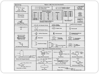
Flowsheet symbols
Toreduce detailed written descriptions on flowsheets, it is
usual practice to develop or adopt a set of symbols and codes
which suit the purpose.
Many symbols are pictorial which is helpful in representing
process as well as control and mechanical operations.
Process Deliverables
Equipment ProcessDatasheets - Process datasheet formats of equipments
typically used in process and petroleum plants.
Heat & Mass Balance - Definition and description of heat and mass balance
charts.
Instrument Process Datasheets - Process datasheet formats of
instruments typically used in process and petroleum plants.
Material Selection Diagrams (MSDs) - Definition, objective and typical
contents of a material selection diagram.
Piping and Instrumentation Diagrams (P&IDs) - Definition,
Typical P&IDs for various systems, Typical P&ID symbols for different
equipments, instruments, fittings etc.
Process Flow Diagrams (PFDs) - Definition and description of PFDs and
typical P&IDs of various process plants.
Safeguarding Memorandum - Definition, objective and typical contents of a
safeguarding memorandum document.
#4 The chemical engineer must never lose sight of the practical limitations involved in a design. It may be possible to determine an exact pipe diameter for an optimum economic design, but this does not mean that this exact size must be used in the final design. Suppose the optimum diameter were, 3.43 in. (8.71 cm).
It would be impractical to have a special pipe fabricated with an inside diameter of 3.43 in. Instead, the engineer would choose a standard pipe size which could be purchased at regular market prices. In this case, the recommended pipe size would probably be a standard 3$in.-diameter pipe having an inside diameter of 3.55 in. (9.02 cm).
#5 The chemical engineer must never lose sight of the practical limitations involved in a design. It may be possible to determine an exact pipe diameter for an optimum economic design, but this does not mean that this exact size must be used in the final design. Suppose the optimum diameter were, 3.43 in. (8.71 cm).
It would be impractical to have a special pipe fabricated with an inside diameter of 3.43 in. Instead, the engineer would choose a standard pipe size which could be purchased at regular market prices. In this case, the recommended pipe size would probably be a standard 3$in.-diameter pipe having an inside diameter of 3.55 in. (9.02 cm).
#32 A spectacle blind or spec blind, is a safety device used to isolate a section of line or piece of equipment when the line or equipment needs to be inspected or removed from service. It is different than a valve in that the blind is a permanent or long term isolation device.
A spectacle blind is machined from a single piece of metal that is cut to match the pipe size, fit between two pipe flanges and requires an additional gasket when it is installed. Also, the bolts will need to be lengthened depending on what piping class and size blind is used. The thickness of the spectacle blind is specified based on the line pressure and pipe size.
One end of the blind will have an opening to allow flow through the pipe during operation and the other end is solid to block flow during maintenance.
TYPES OF SPECTACLE BLINDS
RING SPACER
Ring spacers are bored to the matching pipe ID and are the same thickness as the "single blind" that it replaces. When removing a "single blind", either the flange and associated piping must be pulled together to seal the line, or a "ring spacer" must be installed to fill the gap. Thick single blinds or rigid piping systems normally require ring spacers.
SINGLE/ LINE BLIND OR BLANK
A positive shut-off device normally installed adjacent to, or in conjunction with, a valve. Their purpose is to prevent accidental flow through a pipeline to a vessel. With the exception of cast iron, plastic, or fiberglass services, they are not drilled with bolt holes, but fit inside the bolt circle of mating flanges. Pipeline blinds or blanks are not the same as bolting blind flanges. Single blinds ues standard gaskets.
A combination of a "single blind' and a "ring spacer" can be fabricated for field convenience as a single unit. Weight consideration and the associated difficulty of handling heavy pieces in the field are a primary consideration in specifying a "spectacle blind" or a combination of blinds. Spectacle blinds are meant to be rotated to change blind/spacer orientation.
SPECTACLE BLIND
A spec blind is a combination of a ring spacer and single blind. They are usually permanently installed in a piping system and rotated as needed.
VAPOR BLIND
Similar to a "single blind", but thinner, normally 1/8" (3mm) to 5/16" (8mm) thick. These are positive sealing devices intended to prevent accidental flow or leakage of vapors into a pipeline or vessel, usually while the system is in service. Vapor blinds are not to be subject to differential pressure.
TEST BLANK
A test blank is specially designed blank used for hydrostatic or other incompressible fluid testing purposes only. Their advantage is cost and weight savings since higher allowable stress values (or lower safety factors) are used in their design.
http://piping-designer.com/index.php/disciplines/mechanical/83-stationary-equipment/pipe-flanges/92-spectacle-blind?title=Spectacle_Blind.
#37 This example shows 2" insulation for the purpose of heat conservation. Other examples might be CC for cold conservation, FP for fire protection or PS for personnel safety. Some coatings might be C for cement lined pipe, F for fiberglass, G for galvanized, P for plastic.
This example shows steam tracing as the type of heat tracing. Other examples might be ET for electrical tracing.
#62 In this schematic the single absorption column contains the characteristics of both contactor and scrubber while in some cases these are separate i.e. contactor tower/column and inlet scrubber vessel.


![[Qualitative process flow diagram for the manufacture of nitric acid by the
ammonia-oxidation process].](https://image.slidesharecdn.com/1sttopicintroductiontoprocessdesign-250410074431-5110997b/85/1st-Topic-Introduction-to-Process-Design-ppt-17-320.jpg)
![An example of a quantitative flow diagram is shown in the following figure:
[Quantitative process flow diagram for the manufacture of nitric acid by the ammonia-
oxidation process].](https://image.slidesharecdn.com/1sttopicintroductiontoprocessdesign-250410074431-5110997b/85/1st-Topic-Introduction-to-Process-Design-ppt-18-320.jpg)
![An example of a combined flow diagram is shown in the following figure:
[Combined flow diagram for the manufacture of nitric acid by the ammonia-
oxidation process].](https://image.slidesharecdn.com/1sttopicintroductiontoprocessdesign-250410074431-5110997b/85/1st-Topic-Introduction-to-Process-Design-ppt-19-320.jpg)


![[Combined process flow diagram for the manufacture of nitric acid by the
ammonia-oxidation process].](https://image.slidesharecdn.com/1sttopicintroductiontoprocessdesign-250410074431-5110997b/85/1st-Topic-Introduction-to-Process-Design-ppt-27-320.jpg)