This document describes a proposed wheeled pipeline inspection robot. It aims to address issues with irregular motion and loss of contact (motion singularity) that occur when conventional robots navigate curved and branched pipelines. The proposed robot features three wheels that are not fixed at 120 degree intervals, allowing the wheels to remain in contact with the pipe surface through turns. Its motion is analyzed through simulations of traveling through straight and curved pipes of varying diameters. The results show the robot can successfully navigate different pipeline scenarios and configurations to overcome limitations of previous designs.
![© 2022, AJCSE. All Rights Reserved 40
RESEARCH ARTICLE
Pipeline Inspection Robot Monitoring System
Muhammad Ahmad Baballe1
*, Mukhtar Ibrahim Bello2
, Adamu Hussaini3
,
Usman Shuaibu Musa3
1
Department of Computer Engineering Technology, School of Technology, Kano State Polytechnic,
Kano, Nigeria, 2
Department of Computer Science, School of Technology, Kano State Polytechnic, Kano,
Nigeria, 3
Department of Computer Science and Information Sciences, Towson University, Towson,
Maryland, USA
Received on: 10/02/2022; Revised on: 25/02/2022; Accepted on: 13/03/2022
ABSTRACT
The most popular method for transporting fluids and gases is through pipelines nowadays. Regular
inspection is necessary for the pipelines to work correctly. Humans must not enter potentially dangerous
environments to inspect these pipelines. As a result of this, pipeline robots came into existence. These
pipe inspection robots help in pipeline inspection, protecting numerous people from harm since human
beings cannot enter the pipes and inspect them in case there is any such or kind of damage that requires
repair. Despite numerous improvements, pipeline robots still have several limitations. The introduction
of this in pipe inspection robots helps to solve many problems, such as leakage of the gas or fluid
pipelines, rustiness, and also if the pipe is broken from any part.
Key words: Broken, Inspection robot, Leakage, Pipeline
INTRODUCTION
Pipelines are now the most widely used method of
transport for gases and liquids (63-65). Therefore,
ongoing pipeline monitoring is necessary to
assure its safety and health.[1]
The most widely
utilized non-destructive testing inspection
techniques are optical testing, radiographic
testing, ultrasonic testing, and hydrostatic testing,
among others.[2]
However, because of recent
advancements in robotic technology,[66,67]
they are
now the preferable choice. Robots are a superior
choice because it is challenging for people to
access a small pipeline.[3]
In-Pipe Inspection
Robots (IPIR) have undergone a great deal of
improvement recently, and these advancements
are categorized according to their various
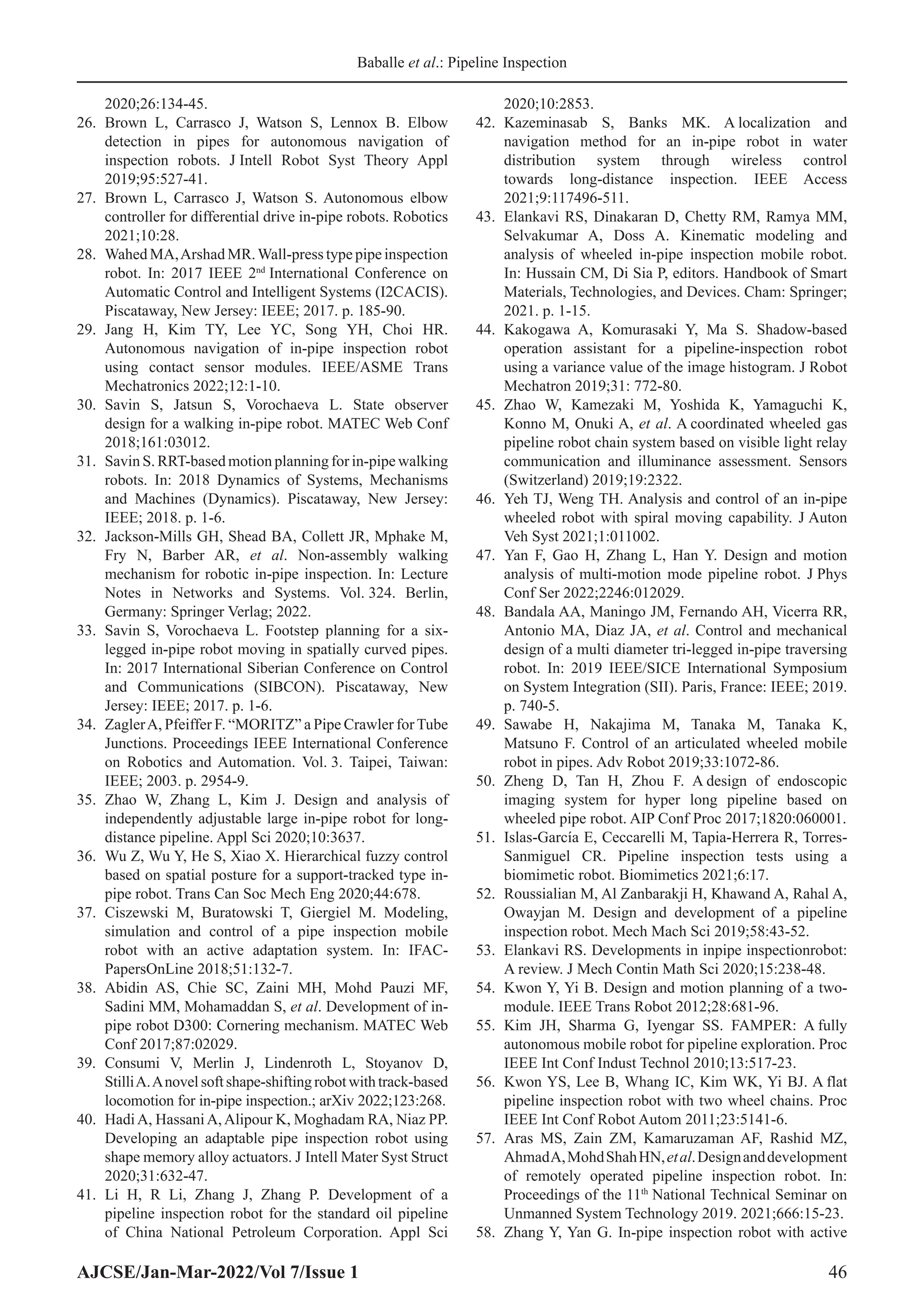
locomotion patterns. Figure 1 shows examples of
thepipelineinspectiongauge(PIG),[9,10]
screw,[16,17]
inchworm,[18-24]
wall press,[25-29]
walking,[30-34]
caterpillar,[35-39]
and wheel type.[40-52]
These
popular forms of movement have drawbacks in
addition to their benefits.[53]
Address for correspondence:
Muhammad Ahmad Baballe
E-mail: mbaballe@kanopoly.edu.ng
Robotic IPIR
The PIG type can be utilized for large distances[4,8]
and moves inside pipelines using water pressure.
The inside surface of the pipelines are not
harmed by the screw-helical type’s motion when
it moves.[11-15]
The inchworm may pass through
pipelines because of its strong grasp despite its
poor traction.[18-22]
The wall press type steadily
passes through the pipelines using contact
force.[25-29]
The walking kind employs legs to
move and has a complex mechanism, which
causes reduced surface wear and slippage.[30,34]
Caterpillars move inside pipelines using tracked
wheels, and its system enables them to adjust to
the circumstances there.[35-39]
The wheel type is
more mobile than the other varieties and can travel
inside pipelines by simply rotating its wheels.[40-44]
Due to the pipeline’s curved and branching pipes,
these robots must overcome numerous obstacles.
It encounters motion singularity and erratic motion
while doing this.[5-7]
Motion singularity
The “Motion Singularity” is the loss of contact
between a robot and pipeline intersections such
Available Online at www.ajcse.info
Asian Journal of Computer Science Engineering 2022;7(1):40-47
ISSN 2581 – 3781](https://image.slidesharecdn.com/05ajcse19122-240309044445-5103736f/75/Pipeline-Inspection-Robot-Monitoring-System-1-2048.jpg)
![Baballe et al.: Pipeline Inspection
AJCSE/Jan-Mar-2022/Vol 7/Issue 1 41
curved pipes, L-branch pipes, and T-branch
pipes.[54,55]
Due to its powerful traction force
and substantial contact area, the caterpillar robot
offers more stability and is the most widely used
IPIR. The pipeline is kept in contact with the inner
surface no matter how the pipeline is turning
using tracked wheels.[35,39,54,55]
If one of the wheels
loses contact with the inner surface of the pipe,
it is unable to pass through it, leading to motion
singularity.[54]
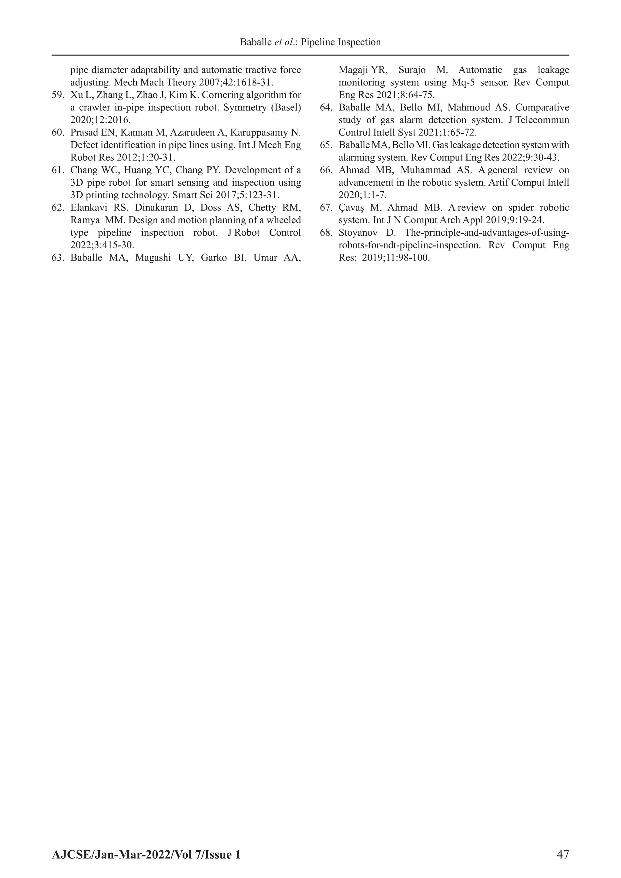
In Figure 2, a caterpillar robot
that is travelling through T-branch pipes uses
two modules in place of one to prevent motion
singularity. Three caterpillar wheels are mounted
on the first module at a 120° angle to one another,
and the second module is infix at a 60° angle
to the front module.[54]
A pipeline exploration
robot named “FAMPER” loses contact with the
inner surface of the pipeline while turning at
Y and T-branch pipes, which results in motion
singularity. The caterpillar wheels were positioned
at a 5° inclination with regard to the robot body
rather than set straight to compensate for the
loss of contact. “Motion singularity” is thereby
avoided.[55]
A two-wheel chain robot that avoids
the motion singularity is shown in.[56]
Irregular motion
According to published research, many
conventional wheeled robots use wheels that
are symmetrically positioned at a 120° angle
to ensure even loading and improved stability
while moving through pipelines. The wall
press characteristic is how the wheeled robots
acquire this stability.[35,54,57,59]
According to,[41,42]
the inclusion of six wheels corrects the uneven
motion that occurs along the circumferential axis
of the pipeline in forward motion caused by the
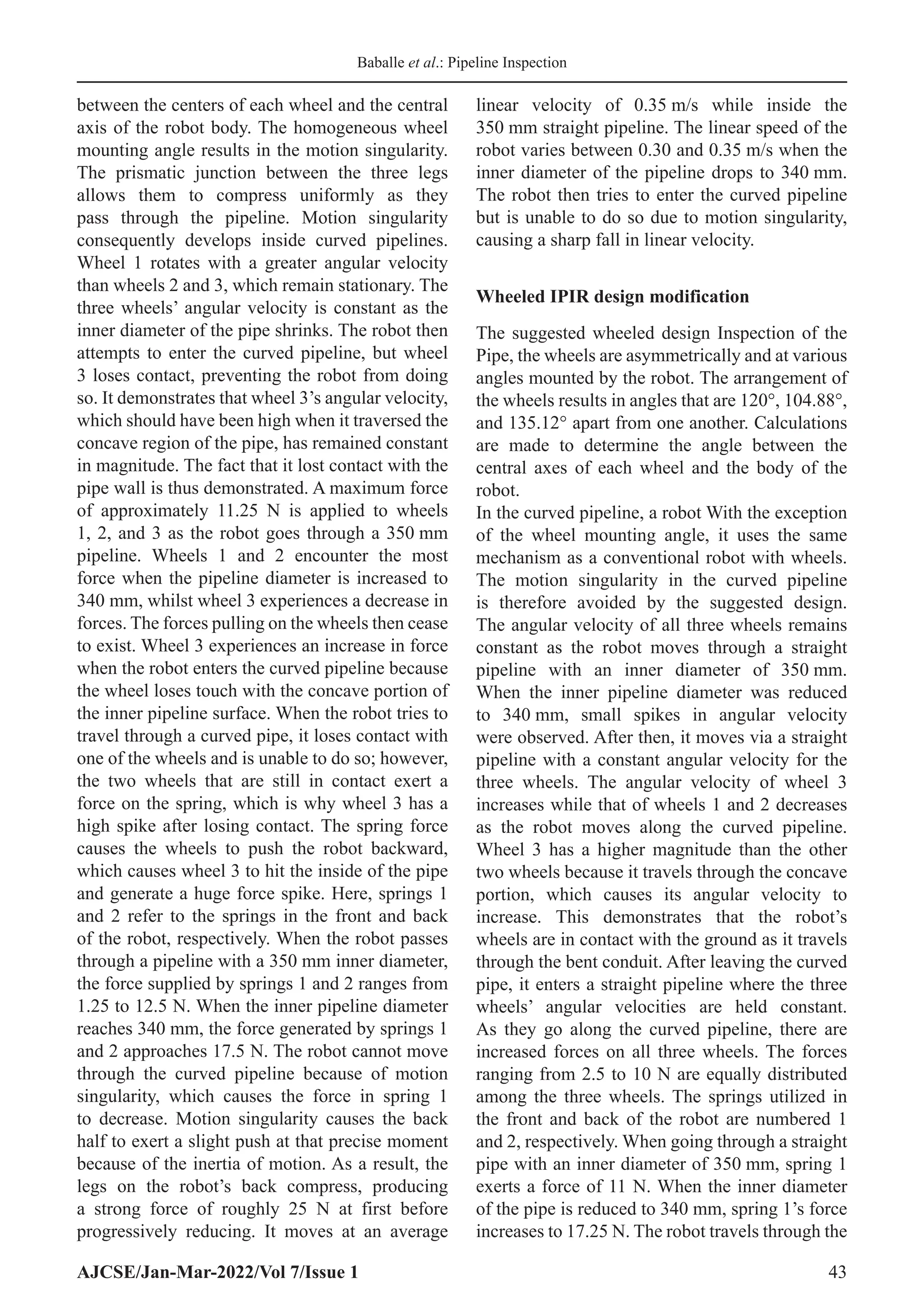
three-wheel arrangement in wheeled IPIR. The
wheeled robot has a three-wheel layout and moves
inside the pipelines using two different types of
wheels.[24,58,63-65]
One has single wheels, whereas
the other has double wheels, as seen in Figure 3.
When moving forward, the robot’s single three-
wheel design tries to rotate in the pipeline’s
circumferential direction.[60]
Only straight
pipelines have been the subject of investigations
about their motion. The orientation of the robot at
the completing end is different from the starting
end in circumstances[61]
where it tries to roll
over to maneuver through the curved pipeline.
In addition, steering inside branching pipes is
challenging due to how the wheels are positioned.
To avoid motion singularity and irregular motion
while retaining the same orientation before and
Figure 1: Different types of in-pipe inspection robots
Figure 2: Two-module collaborative indoor pipeline
inspection robot](https://image.slidesharecdn.com/05ajcse19122-240309044445-5103736f/75/Pipeline-Inspection-Robot-Monitoring-System-2-2048.jpg)
![Baballe et al.: Pipeline Inspection
AJCSE/Jan-Mar-2022/Vol 7/Issue 1 42
after entering the curved pipeline, this research
focuses on constructing a wheeled IPIR with a
single three-wheel arrangement.[62]
Contribution
To address the issue of irregular motion and
motion singularity occurring in pipelines, a
wheeled type IPIR is proposed and developed in
this research. The wheels on this robot are different
from those on conventional robots in that they are
not fixed at a 120° angle from one another. The
location of the wheels guarantees that the robot’s
wheels are always in contact with the pipe surface
and prevents the robot from rolling over when
moving along a curved pipeline. It also aids the
robot’s navigation through branched pipes.[62]
RESOURCES AND TECHNIQUES
Initially, we used the Solidworks program to
design the robot. To ADAMS, the created model
is exported. Using the limitations listed in the
flowchart, motion analysis is performed for the
robot. The findings are then discussed. Links,
wheels, clamps, a central shaft, legs, a spring, a
fixed joint, and a prismatic joint are all features
of the proposed robot. Inside pipelines, the legs
provide improved stability. The legs are supported
bythesmalllinkages.Allofthepartsarekeptwhere
they belong thanks to the clamps. The wheels are
designed to increase mobility within pipelines. All
of the modular parts are linked to the central shaft,
which serves as the primary body. The prismatic
joint, which is the moveable joint and the one
that generates the force required for the wheels to
make contact with the inner surface of the pipeline,
moves while the fixed joint remains stationary.
Spring-based devices that compress and expand
in accordance with the inner circumference of
the pipeline supply the necessary force for the
prismatic junction. The internal pipeline diameter
of the robot can range from 250 mm to 350 mm.
It has three revolute joints and one prismatic joint.
By compressing and stretching the legs, these
joints provide the robot extra stability as it travels
through the pipelines. It helps the robot deal
with various pipeline scenarios, such curved or
T-branch pipes. The actuator scale is ascertained
using static analysis.
DISCUSSION/ANALYSIS
The ADAMS software does the motion analysis.
The robot design is imported from Solidworks
and the boundary conditions for the simulation are
provided by the ADAMS software. Body-to-body
contact, motor rpm, and spring stiffness are
taken into account. Simulations are done for the
proposed robot as well as the conditions when
the wheels are offset by 120°. In the scenario,
the robot first travels inside a 350 mm-diameter
pipeline. After traveling 600 mm, the pipeline’s
inner diameter changes; it decreases by 10 mm,
or 340 mm overall. The robot’s capacity to adjust
to pipelines of various diameters is tested by this
shift in diameter. The robot then passes through
a straight pipe once more before coming to a 90°
curved elbow. It enters the straight pipe once more
after leaving the curved pipe to exit the pipeline.
This simulation scenario tests the robot’s ability
to move through pipes that are straight, curved,
and of different diameters. The only difference
between the simulations’ parameters is the angle
at which the wheels are mounted. Gravity, motor
speed, solid body contact, and spring stiffness are
the criteria the robot must meet in order to travel
through the pipelines. The third wheel serves as
a support wheel, making the three wheels at the
bottom of the robot’s front side functional. The
robot has three inactive wheels at the back. The
motor spins at 100 rpm, and the spring stiffness is
2.826 N/mm.
Robot with wheels for pipe inspection
Traditional wheeled IPIRs have wheels that are
120°apartfromoneanother.Theangleiscalculated
Figure 3: Three-wheel configuration robot](https://image.slidesharecdn.com/05ajcse19122-240309044445-5103736f/75/Pipeline-Inspection-Robot-Monitoring-System-3-2048.jpg)
![Baballe et al.: Pipeline Inspection
AJCSE/Jan-Mar-2022/Vol 7/Issue 1 45
In addition, it can maintain the pipeline in
some locations where manual labor is not
appropriate and quickly identify the internal
sources of pipeline degradation.[68]
CONCLUSION
In this work, we contrast the suggested wheeled
type IPIR with the wheeled type IPIR that is
currently in use. The three wheels are mounted on
the current design at a 120° angle from one another.
Both the suggested and conventional wheeled
forms of IPIR are simulated. The ideal angles are
104.88°, 135.12°, and 120°. Results of velocity
and force analyses for each wheel demonstrate
how this design brings the wheels into contact with
the pipelines. The created robot did not experience
the unequal force experienced by the robot with a
wheel mounting angle of 120° when traversing the
curved pipeline. Also discussed are the effects of
the in-pipe wheel robots.
REFERENCES
1. Adegboye MA, Fung WK, Karnik A. Recent advances
in pipeline monitoring and oil leakage detection
technologies: Principles and approaches. Sensors
(Switzerland) 2019;19:2548.
2. Carvalho AA, Rebello JM, Souza MP, Sagrilo LV,
Soares SD. Reliability of non-destructive test techniques
in the inspection of pipelines used in the oil industry. Int
J Pressure Vessels Piping 2008;85:745-51.
3. Kakogawa A, Ma S. Robotic search and rescue through
in-pipe movement. In: Unmanned Robotic Systems and
Applications. London, UK: Intechopen; 2020.
4. Zhou J, Deng T, Peng J, Liang G, Zhou X, Gong J.
Experimental study on pressure pulses in long-distance
gas pipeline during the pigging process. Sci Prog
2020;103:368.
5. Zhang H, Dong J, Cui C, Liu S. Stress and strain
analysis of spherical sealing cups of fluid-driven
pipeline robot in dented oil and gas pipeline. Eng Fail
Anal 2020;108:104294.
6. Liu C, Wei Y, Cao Y, Zhang S, Sun Y. Traveling ability
of pipeline inspection gauge (PIG) in elbow under
different friction coefficients by 3D FEM. J Nat Gas Sci
Eng 2020;75:103134.
7. Jiang J, Zhang H, Ji B, Yi F, Yan F, Liu X. Numerical
investigation on sealing performance of drainage
pipeline inspection gauge crossing pipeline elbows.
Energy Sci Eng 2021;9:1858-71.
8. Dong J, Liu S, Zhang H, Xiao H. Experiment and
simulation of a controllable multi-airbag sealing disc of
pipeline inspection gauges (PIGs). Int J Press Vessel Pip
2021;192:104422.
9. Chen Z. Deformation and stress analysis of cup
on pipeline inspection gauge based on reverse
measurement. Energy Sci Eng 2022;10:2509-26.
10. Zhang H, Gao MQ, Tang B, Cui C, Xu XF. Dynamic
characteristics of the pipeline inspection gauge under
girth weld excitation in submarine pipeline. Pet Sci
2022;19:774-88.
11. Ren T, Zhang Y, Li Y, Chen Y, Liu Q. Driving
mechanisms, motion, and mechanics of screw drive in-
pipe robots: A review. Appl Sci 2019;9:2514.
12. Tourajizadeh H, Boomeri V, Rezaei M, Sedigh A.
Dynamic optimization of a steerable screw in-pipe
inspection robot using HJB and turbine installation.
Robotica 2020;38:2001-22.
13. Li T, Liu K, Liu H, Cui X, Li B, Wang Y. Rapid design
of a screw drive in-pipe robot based on parameterized
simulation technology. Simulation 2019;95:45.
14. Tourajizadeh H, Rezaei M, Sedigh AH. Optimal control
of screw in-pipe inspection robot with controllable
pitch rate. J Intell Robot Syst 2018;90:269-86.
15. Li P, Tang M, Lyu C, Fang M, Duan X, Liu Y. Design
and analysis of a novel active screw-drive pipe robot.
Adv Mech Eng 2018;10:168.
16. Tu Q, Liu Q, Ren T, Li Y. Obstacle crossing and traction
performance of active and passive screw pipeline
robots. J Mech Sci Technol 2019;33:2417-27.
17. Tourajizadeh H, Rezaei M. Design and control
of a steerable screw in-pipe inspection robot. In:
2016 4th
International Conference on Robotics and
Mechatronics (ICROM). Piscataway, New Jersey:
IEEE; 2016. p. 98-104.
18. Yamamoto T, Sakama S, Kamimura A. Pneumatic
duplex-chambered inchworm mechanism for narrow
pipes driven by only two air supply lines. IEEE Robot
Autom Lett 2020;5:5034-42.
19. Kusunose K, Akagi T, Dohta S, Kobayashi W,
Shinohara T, Hane Y, et al. Development of inchworm
type pipe inspection robot using extension type
flexible pneumatic actuators. Int J Automot Mech Eng
2020;17:8019-28.
20. Hayashi K, Akagi T, Dohta S, Kobayashi W,
Shinohara T, Kusunose K, et al. Improvement of pipe
holding mechanism and inchworm type flexible pipe
inspection robot. Int J Mech Eng Robot Res 2020;9:6.
21. Fang D, Shang J, Luo Z, Lv P, Wu G. Development
of a novel self-locking mechanism for continuous
propulsion inchworm in-pipe robot. Adv Mech Eng
2018;10:345.
22. Khan MB, Chuthong T, Do CD, Thor M, Billeschou P,
LarsenJC,etal.ICrawl:Aninchworm-inspiredcrawling
robot. IEEE Access 2020;8:1.
23. Aliff M, Imran M, Izwan S, Ismail M, Samsiah N,
Shimooka S, et al. Development of pipe inspection
robot using soft actuators, microcontroller and labview.
Int J Adv Comput Sci Appl 2022;13:349-54.
24. Yang J, Xue Y, Shang J, Luo Z. Research on a new
bilateral self-locking mechanism for an inchworm
micro in-pipe robot with large traction. Int J Adv Robot
Syst 2014;11:174.
25. Feng G, Li W, Li Z, He Z. Development of a wheeled
and wall-pressing type in-pipe robot for water pipelines
cleaning and its traveling capability. Mechanika](https://image.slidesharecdn.com/05ajcse19122-240309044445-5103736f/75/Pipeline-Inspection-Robot-Monitoring-System-6-2048.jpg)