Download to read offline

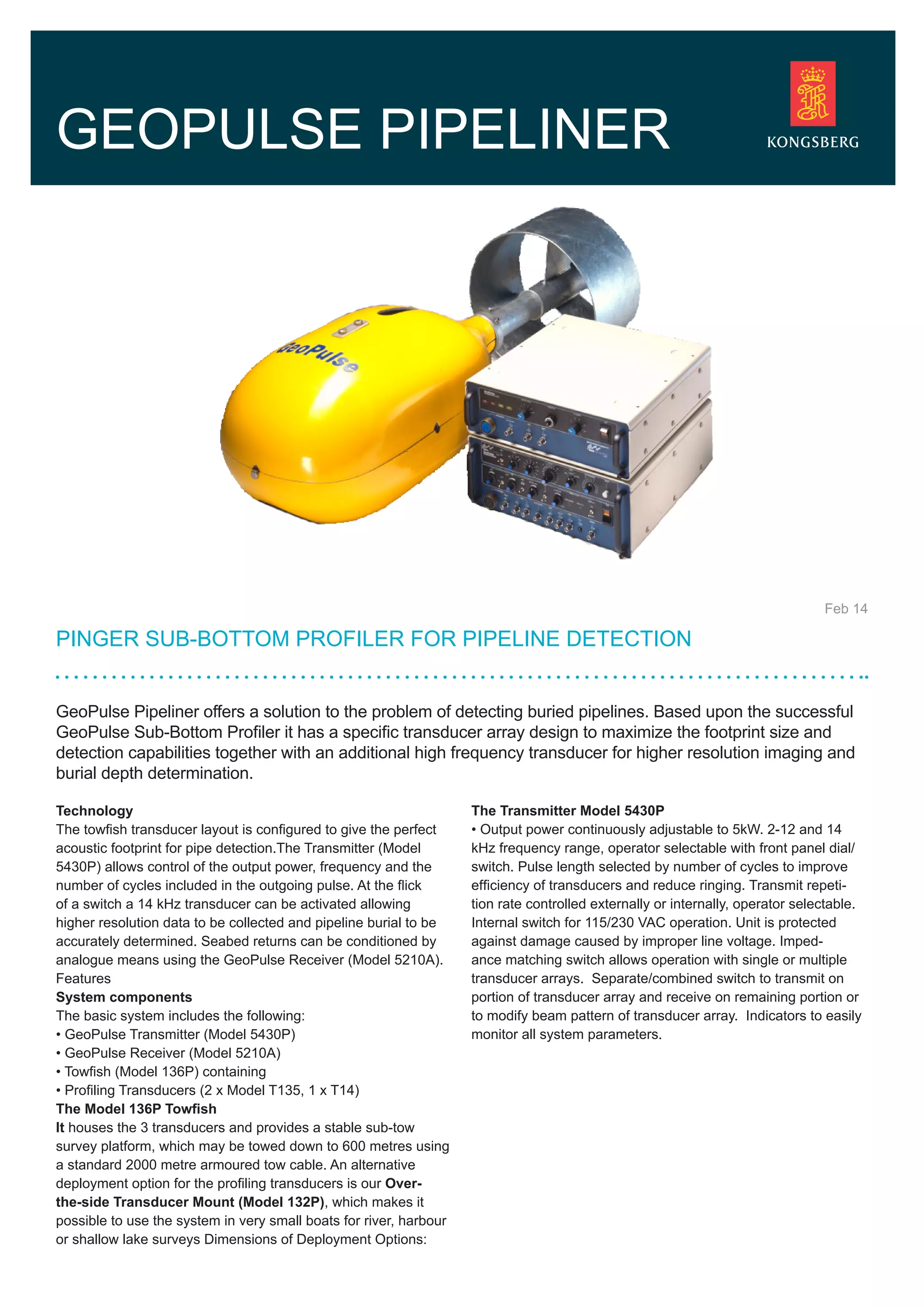

The GeoPulse Pipeliner uses a towfish with multiple transducers, including a high frequency 14 kHz transducer, to detect buried pipelines. It can be deployed over-the-side from small boats or towed up to 600 meters deep. The system includes a transmitter that outputs pulses between 2-12 kHz or 14 kHz and a receiver to process the returning acoustic signals and record data.