Example 2
Answers:
(a)- 6
(b)-0.27 V
A voltage source with source resistance is connected to the input
of an op-amp inverting amplifier circuit
(a) If the and then calculate the voltage gain, VO / VS
(b) Determine the output voltage for the source voltage
4.
Noninverting amplifier
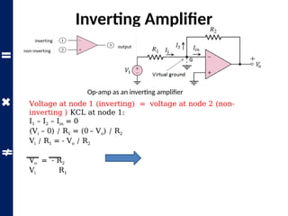
Non -Inverting Amplifier
Voltage at node 1 (inverting) = voltage at node 2
(non-inverting ) KCL at node 1:
i1 – i2 = 0
(0– Vi) / R1 = (Vi – Vo) / R2
-(Vi / R1) = (Vi / R2) – (Vo / R2)
Vo / R2 = (Vi / R2) + (Vi / R1) = Vi 1 + 1
Vo / Vi = R2 1 + 1
R2 R1
R2 R1
Example 1
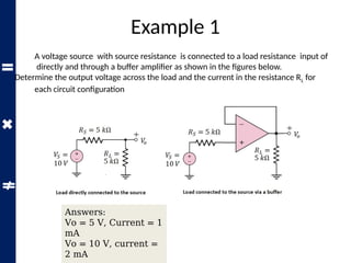
A voltagesource with source resistance is connected to a load resistance input of
directly and through a buffer amplifier as shown in the figures below.
Determine the output voltage across the load and the current in the resistance RL for
each circuit configuration
Answers:
Vo = 5 V, Current = 1
mA
Vo = 10 V, current =
2 mA
7.
Summing Amplifier
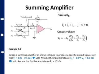
Summing Amplifier
Outputvoltage
i1 + i2 + i3 – i4 – 0 = 0
Similarly,
Example 8.2
Design a summing amplifier as shown in figure to produce a specific output signal, such
that vo = 1.25 – 2.5 cos t volt. Assume the input signals are vI1 = -1.0 V, vI2 = 0.5 cos
t volt. Assume the feedback resistance RF = 10 k
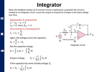
When the feedbackresistor of an inverter circuit is replaced by a capacitor the circuit is
worked as an integrator circuit -cause the output to respond to changes in the input voltage
over time
Integrator
Integrator circuit
11.
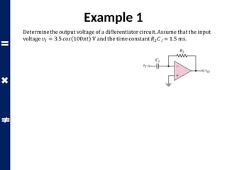
Example 1
The integratorcircuit as shown in figure has an initial voltage V across the capacitor at time. A
step input voltage V is applied at time. Determine the RC time constant necessary such that the
output voltage reaches +10.2 V at time 5.0 ms.
Solution: The output voltage
10.2=−1.4−
(− 2)
𝑅1𝐶
∫
0
5
𝑑𝑡=− 1.4+
2
𝑅1 𝐶
[5]
𝑉𝑜=𝑉 𝑥−
1
𝑅1 𝐶
∫𝑉𝑆 𝑑𝑡
¿𝑉 𝑥 −
1
𝑅1 𝐶
∫
0
5
𝑉 𝑆 𝑑𝑡
𝑅1 𝐶=0.862𝑚𝑠
12.
Differentiator
When the invertinginput terminal resistor of an op-amp inverter circuit is replaced by a
capacitor the circuit is worked as a differentiator circuit.
Differentiator circuit
Because Q =
CVS
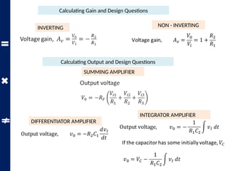
Calculating Gain andDesign Questions
INVERTING NON - INVERTING
Calculating Output and Design Questions
SUMMING AMPLIFIER
DIFFERENTIATOR AMPLIFIER
INTEGRATOR AMPLIFIER
15.
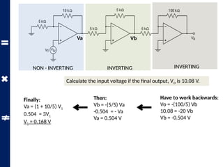
Calculate the inputvoltage if the final output, VO is 10.08 V.
NON - INVERTING INVERTING INVERTING
Va Vb
Have to work backwards:
Vo = -(100/5) Vb
10.08 = -20 Vb
Vb = -0.504 V
Then:
Vb = -(5/5) Va
-0.504 = - Va
Va = 0.504 V
Finally:
Va = (1 + 10/5) V1
0.504 = 3V1
V1 = 0.168 V
16.
Calculate the outputvoltage, VO if V1 = V2 = 700 mV
INVERTING SUMMING
Va
Va = -(500/250) 0.7
Va = -1.4 V
Then:
Vo = - 500 [ Va / 100 + V2 / 50 ]
Vo = - 500 [ -1.4 / 100 + 0.7 / 50 ]
Vo = 0 V
17.
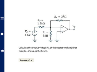
Calculate the outputvoltage VO of the operational amplifier
circuit as shown in the figure.
Answer: -3 V


![Example 1
The integrator circuit as shown in figure has an initial voltage V across the capacitor at time. A
step input voltage V is applied at time. Determine the RC time constant necessary such that the
output voltage reaches +10.2 V at time 5.0 ms.
Solution: The output voltage
10.2=−1.4−
(− 2)
𝑅1𝐶
∫
0
5
𝑑𝑡=− 1.4+
2
𝑅1 𝐶
[5]
𝑉𝑜=𝑉 𝑥−
1
𝑅1 𝐶
∫𝑉𝑆 𝑑𝑡
¿𝑉 𝑥 −
1
𝑅1 𝐶
∫
0
5
𝑉 𝑆 𝑑𝑡
𝑅1 𝐶=0.862𝑚𝑠](https://image.slidesharecdn.com/opamp2-250908164542-3828895e/85/Physics-inverting-amplifiers-in-pptx-and-more-11-320.jpg)

![Calculate the output voltage, VO if V1 = V2 = 700 mV
INVERTING SUMMING
Va
Va = -(500/250) 0.7
Va = -1.4 V
Then:
Vo = - 500 [ Va / 100 + V2 / 50 ]
Vo = - 500 [ -1.4 / 100 + 0.7 / 50 ]
Vo = 0 V](https://image.slidesharecdn.com/opamp2-250908164542-3828895e/85/Physics-inverting-amplifiers-in-pptx-and-more-16-320.jpg)