This document is a dissertation proposal by Benjamin Braaten on properties of multiple microstrip antennas in layered anisotropic materials. The proposal provides background on microstrip antennas and previous related work. It then outlines the proposed research questions on determining input impedance and mutual impedance of antennas in layered anisotropic structures. The technical objectives and work plan involve choosing antenna types, developing numerical techniques, and validating results with experiments on designed structures. The proposal seeks to advance understanding of antenna properties in complex layered anisotropic materials.

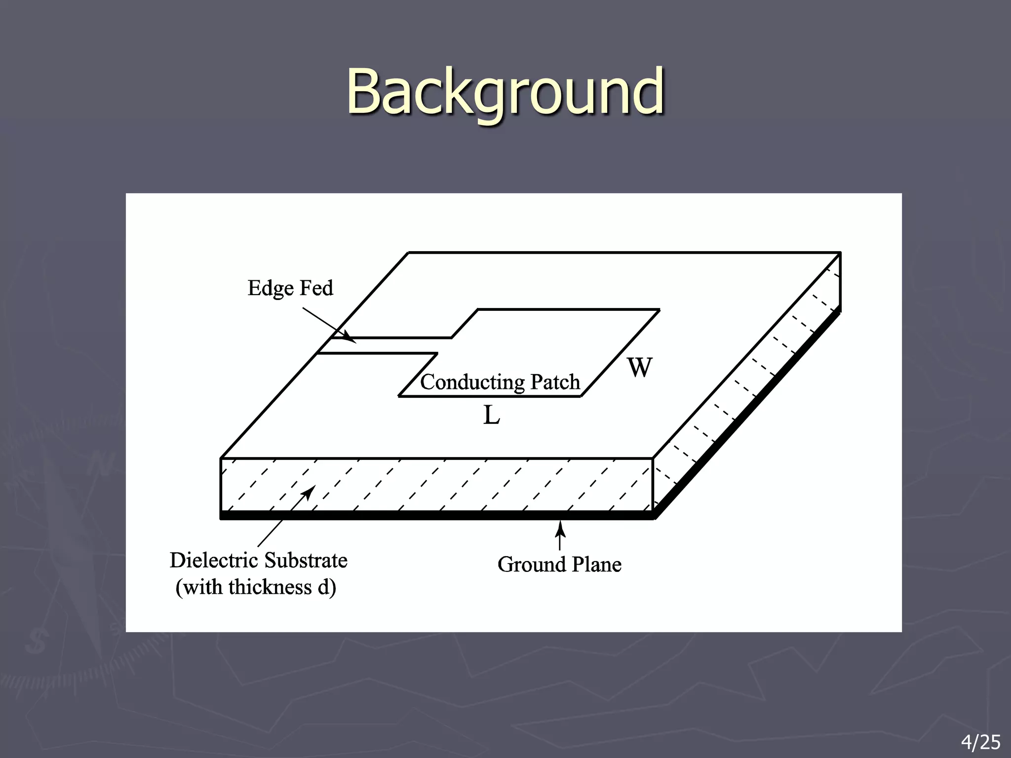
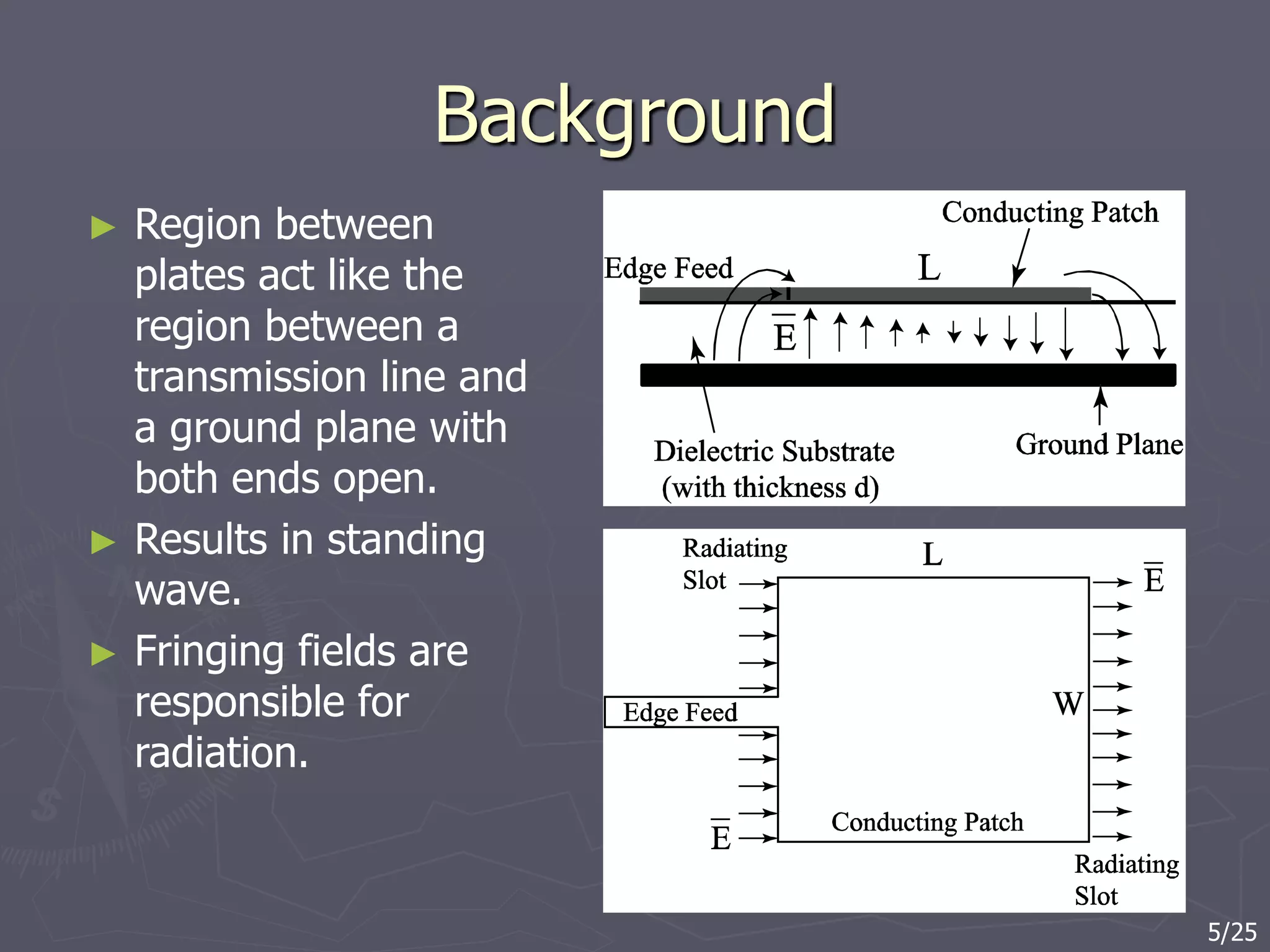
![Background
► Since Deschamps's [1] formal presentation of a microstrip
antenna in 1953 and detailed discussion by Alexopoulos
[2] there has been an extensive amount of research
devoted to the study of various printed antennas and
arrays.
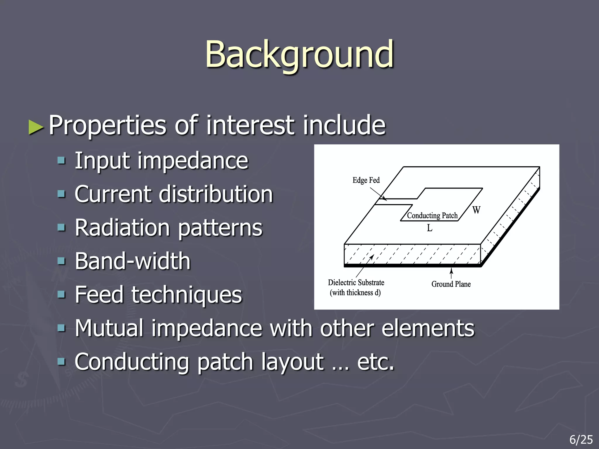
► It is well known that printed antennas are [3]
very light
occupy a small volume
are useful at higher frequencies (f>1GHz)
provide a wide range of patterns
[1] G.A. Deschamps, “Microstrip Microwave Antennas,” 3rd USAF Symposium on Antennas, 1953.
[2] N.G. Alexopoulus, “Integrated-circuit structures on anisotropic substrates,” IEEE Transactions
on Microwave Theory and Techniques, Vol. 33, No. 10, October 1985, pp. 847-881.
[3] David M. Pozar and Daniel H. Schaubert, “Microstrip Antennas: The analysis and Design of
Microstrip Antennas and Arrays,” IEEE Press, Piscataway, NJ, 1995.
3/25](https://image.slidesharecdn.com/phdproposalpresentation-210601053928/75/Phd-proposal-presentation-3-2048.jpg)
![Previous work-isolated antennas
► In 1979 a significant step was
taken by Uzunoglu,
Alexopoulos and Fikioris [9]
microstrip dipoles
radiation propoerties
Based on Green’s function for
a hertizian dipole over a
grounded isotropic substrate
► Working from that base, Rana
and Alexopoulos presented
work in 1981 on the current
distribution and input
impedance of printed dipoles
[10].
[9] N.K. Uzunoglu, N.G. Alexopoulos and J.G. Fikioris, “Radiation properties of microstrip dipoles,'‘
IEEE Transactions on Antennas and Propagation, Vol. 27, No. 6, November 1979, pp. 853-858.
[10] I.E. Rana and N.G. Alexopoulos, “Current distribution and input impedance of printed dipoles,”
IEEE Transactions on Antennas and Propagation, Vol. 29, No. 1, January 1981, pp. 99-105.
7/25](https://image.slidesharecdn.com/phdproposalpresentation-210601053928/75/Phd-proposal-presentation-7-2048.jpg)
![Previous work-isolated antennas
► The above work with Green's functions in the spectral form laid the
foundation for future work by Pozar [11] and others to analyze
properties of other various microstrip antennas.
► In parallel with the development by Alexopoulos and his colleagues, in
1980 and 1981, Itoh and Mentzel [12]-[13] developed a spectral
domain immittance approach.
► This lead to the work by Lee and Tripathi [15] and later Nelson, Rogers
and d’Assuncao [16] to study layered anisotropic structures.
[11] D.M. Pozar, “Input impedance and mutual coupling of rectangular microstrip antennas,”
IEEE Transactions on Antennas and Propagation, Vol. 30, No. 6, November 1982, pp. 1191-1196.
[12] T. Itoh, “Spectral domain immitance approach for dispersion characteristics of generalized printed
transmission lines,” IEEE Transactions on Antennas and Propagation, Vol. 28, No. 7, July 1980, pp. 733-736.
[13] T. Itoh and W. Menzel, “A full-wave analysis method for open microstrip structures,”
IEEE Transactions on Microwave Theory and Techniques, Vol. 29, No. 1, January 1981, pp. 63-68.
[15] H. Lee and V.K. Tripathi, “Spectral domain analysis of frequency dependent propagation characteristics
of planar structures on uniaxial medium,” IEEE Transactions on Microwave Theory and Techniques, Vol.
30, No. 8, August 1982, pp. 1188-1193.
[16] R.M. Nelson, D.A. Rogers and A.G. D'Assuncao, “Resonant frequency of a rectangular microstrip patch
on several uniaxial substrates,” IEEE Transactions on Antennas and Propagation, Vol. 38, No. 7,
July 1990, pp. 973-981. 8/25](https://image.slidesharecdn.com/phdproposalpresentation-210601053928/75/Phd-proposal-presentation-8-2048.jpg)
![Previous work-mutual coupling
► In 1981, Alexopoulos and Rana [22] study the mutual
impedance between printed dipoles (Green’s function in
spectral form)
► Then in 1982, Pozar
presents the mututal
impedance between
rectangular microstrip
antennas [11]
[22] N.G. Alexopoulos and I.E. Rana, “Mutual impedance computation between printed dipoles,”
IEEE Transactions on Antennas and Propagation, Vol. 29, No. 1, January 1981, pp. 106-112.
[11] D.M. Pozar, “Input impedance and mutual coupling of rectangular microstrip antennas,”
IEEE Transactions on Antennas and Propagation, Vol. 30, No. 6, November 1982, pp. 1191-1196.
9/25](https://image.slidesharecdn.com/phdproposalpresentation-210601053928/75/Phd-proposal-presentation-9-2048.jpg)
![Current work
► In 1998, Waterhouse, Targonski and Kokotoff [36]
discuss the design and performance of using shorting
posts on a microstrip patch antenna on an isotropic
substrate.
► In 2001, Verma and Nisimuddin [34] investigate the
input impedance of rectangular microstrip antennas
Different from work by Oliveira and d’Assuncao [20]
[36] R.B. Waterhouse, S.D. Targonski and D.M. Kokotoff, “Design and performance of small printed
antennas,” IEEE Transactions on Antennas and Propagation, Vol. 46, No. 11, November 1998.
[20] J.R.S. Oliveira and A.G. D'Assuncao, “Input impedance of microstrip patch antennas on anisotropic
dielectric substrates,” Antennas and Propagation Society International Symposium, 1996. AP-S. Digest,
Vol. 2, July 21-26, 1996, p. 1066-1069.
[34] A.K. Verma and Nasimuddin, “Input impedance of rectangular microstrip patch antenna with
iso/anisotropic substrate-superstrate,'‘ IEEE Microwave and Wireless Components Letters, Vol. 11, No. 11,
November 2001, pp. 456-458.
10/25](https://image.slidesharecdn.com/phdproposalpresentation-210601053928/75/Phd-proposal-presentation-10-2048.jpg)
![Current work
► Also in 2001, Shackelford,
Lee, Chatterjee, Guo, Luk
and Chair [39] present a
small-sized wide-band U-
slot and L-probe fed
microstrip antenna with
shorting walls.
[34] A. Shackelford, K.F. Lee, D. Chatterjee, Y.X. Guo,
K.M. Luk and R. Chair, “Small-size wide-bandwidth
microstrip patch antennas,” IEEE Antennas and
Propagation Society International Symposium, 2001,
Vol. 1, July 8-13, 2001, pp. 86-89.
11/25](https://image.slidesharecdn.com/phdproposalpresentation-210601053928/75/Phd-proposal-presentation-11-2048.jpg)
![Current work
► In 2003 Yang and Samii [48] presented a low mutual coupling design
of an array of electromagnetic band gap structures.
Used FDTD
Single anisotropic substrate
► In 2005 Chair, Kishk and Lee [49] presented work on the mutual
coupling between a 2 element array of circular patch antennas.
Used IE3D [44]
Single isotropic substrate on an isotropic dielectric substrate.
► Then, in 2007, Buell, Mosallaei and Sarabandi [45] used metamaterial
to suppress the mutual coupling between elements in a densely packed
array.
metamaterial as isolation walls between the elements.
[48] F. Yang and Y. Rahmatt-Samii “Microstrip antennas integrated with electromagnetic band-gap
(EBG) structures: a low mutual coupling design for array applications,'‘ IEEE Transactions on Antennas
and Propagation, Vol. 51, No. 10, October 2003, pp. 2936-2946.
[49] R. Chair, A.A. Kishk and K-F. Lee, “Comparative study on the mutual coupling between different
sized cylindrical dielectric resonators antennas and circular microstrip patch antennas,” IEEE Transactions
on Antennas and Propagation, Vol. 53, No. 3, March 2005, pp. 1011-1019.
[44] www.zeland.com.
[45] K. Buell, H. Mosallaei and K. Sarabandi, “Metamaterial insulator enabled superdirective array,”
IEEE Transactions on Antennas and Propagation, Vol. 55, No. 4, April 2007, 1074-1085. 12/25](https://image.slidesharecdn.com/phdproposalpresentation-210601053928/75/Phd-proposal-presentation-12-2048.jpg)
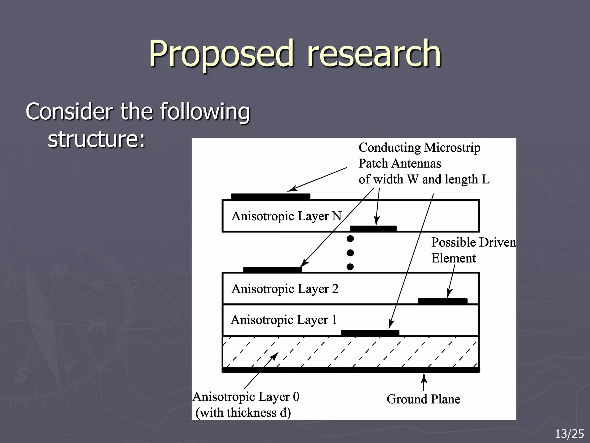

![Proposed research
The previous two questions are very
significant in many fields.
Microstrip antenna arrays [3].
Frequency Selective Structures (FSS) [53]
Radio Frequency Identification (RFID) [56]
[3] David M. Pozar and Daniel H. Schaubert, “Microstrip Antennas: The analysis and Design of
Microstrip Antennas and Arrays”, IEEE Press, Piscataway, NJ, 1995.
[53] A.L.P.S. Campos an A.G. d'Assuncao, “Scattering paramters of a frequnecy selective surface
between anisotropic dielectric layers for incidnet co-polarized plane waves,” IEEE Antennas and
Propagation Society International Symposium, 2001, Vol. 4, July 8-13, 2001, p. 382-385.
[56] K. Finkenzeller, RFID Handbook:Fundamentals and Applications in Contactless Smart Cards
and Identification, John Wiley and Sons, West Sussex, England, 2003.
15/25](https://image.slidesharecdn.com/phdproposalpresentation-210601053928/75/Phd-proposal-presentation-15-2048.jpg)

![Work Plan
► Choose the appropriate types of microstrip
antennas that will allow the work to proceed to
answer the proposed questions.
Printed dipoles by Alexopoulos and Rana [10]
Rectangular microstrip antennas by Nelson [16], Pozar
[19], and Oliveira [20].
UWB
[10] I.E. Rana and N.G. Alexopoulos, “Current distribution and input impedance of printed dipoles,”
IEEE Transactions on Antennas and Propagation, Vol. 29, No. 1, January 1981, pp. 99-105.
[16] R.M. Nelson, D.A. Rogers and A.G. D'Assuncao, “Resonant frequency of a rectangular microstrip patch
on several uniaxial substrates,” IEEE Transactions on Antennas and Propagation, Vol. 38, No. 7,
July 1990, pp. 973-981.
[19] D.M. Pozar, “Radiation and scattering from a microstrip patch on a uniaxial substrate,” IEEE
Transactions on Antennas and Propagation, Vol. 35, No. 6, June 1987, pp. 613-621.
[20] J.R.S. Oliveira and A.G. D'Assuncao, “Input impedance of microstrip patch antennas on anisotropic
dielectric substrates,” Antennas and Propagation Society International Symposium, 1996. AP-S. Digest,
Vol. 2, July 21-26, 1996, p. 1066-1069. 17/25](https://image.slidesharecdn.com/phdproposalpresentation-210601053928/75/Phd-proposal-presentation-17-2048.jpg)
![Work Plan
► Choose and develop the numerical technique that can be used to
compute the input impedance and mutual coupling between elements
in the anisotropic structure.
Exact Green’s function [11, Pozar]
► Numerical integration and derivatives are extensive
► Developed to evaluate problems with anisotropic material
► Developed to evaluate problems with multiple anisotropic layers
Equivalent magnetic source [30, Benalla]
► Field expression are much simpler
► Numerical integration and derivatives are extensive
► Needs to be extended to evaluate the problems proposed here
Spectral domain immittance method [16, Nelson]
► Derivation is lengthy
► Needs to be developed to compute mutual impedance
► Numerical integration is nice
► No derivative approximations
► Developed to evaluate problems with multiple anisotropic materials
18/25](https://image.slidesharecdn.com/phdproposalpresentation-210601053928/75/Phd-proposal-presentation-18-2048.jpg)
![Work Plan
►Validate numerical results for the isotropic
case with commercially available software.
Use Momentum in Advanced Design System
(ADS) [64].
Reproduce printed dipole work by Rana and
Alexopoulos [22].
Reproduce rectangular microstrip results by
Pozar [11].
[22] N.G. Alexopoulos and I.E. Rana, “Mutual impedance computation between printed dipoles,”
IEEE Transactions on Antennas and Propagation, Vol. 29, No. 1, January 1981, pp. 106-112.
[11] D.M. Pozar, “Input impedance and mutual coupling of rectangular microstrip antennas,”
IEEE Transactions on Antennas and Propagation, Vol. 30, No. 6, November 1982, pp. 1191-1196.
[64] www.agilent.com.
19/25](https://image.slidesharecdn.com/phdproposalpresentation-210601053928/75/Phd-proposal-presentation-19-2048.jpg)

![Work Plan
► Design and build a multiple
layered structure to
measure and validate the
numerical calculations of
input impedance and
mutual coupling.
Jadlecka, Poe and Carver
[24] – measurement
technique
Validates code with
measurements
[24] R.P. Jedlicka, M.T. Poe and K.R. Carver,
“Measured mutual coupling between microstrip
antennas,” IEEE Transactions on Antennas
and Propagation, Vol. 29, No. 1, January 1981.
21/25](https://image.slidesharecdn.com/phdproposalpresentation-210601053928/75/Phd-proposal-presentation-21-2048.jpg)

![Significance of anticipated results
► Mutual impedance will significantly effect input impedance
of driven elements
► Appropriate values of permittivity could possibly minimize
mutual impedance (Krowne [17] and Wang [62])
► Possible reduction of array surface area
Values of permittivity
Conducting surface on multiple layers
► UWB antennas
► 60GHz-90GHz band
► Dual frequency antennas
► RFID systems
[17] C.M. Krowne, “Green's function in the spectral domain for biaxial and uniaxial anisotropic planar
dielectric structures,” IEEE Transactions on Antennas and Propagation, Vol. 32, No. 12, December 1984.
[62] W.J. Wang, “Multilayered printed antennas with biaxial anisotropic dielectric substrates:
general analysis and case studies,” Ph.D. Dissertation, Polytechnic University, January 2002.
23/25](https://image.slidesharecdn.com/phdproposalpresentation-210601053928/75/Phd-proposal-presentation-23-2048.jpg)