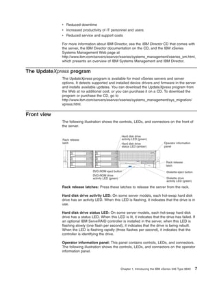
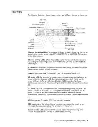
8. Läs säkerhetsinformationen innan du installerar den här produkten.
Important:
All caution and danger statements in this documentation begin with a
number. This number is used to cross reference an English caution or
danger statement with translated versions of the caution or danger
statement in the IBM Safety Information book.
For example, if a caution statement begins with a number 1,
translations for that caution statement appear in the IBM Safety
Information book under statement 1.
Be sure to read all caution and danger statements in this
documentation before performing the instructions. Read any additional
safety information that comes with your server or optional device before
you install the device.
Statement 1
Danger
Electrical current from power, telephone, and communication cables is hazardous.
To avoid a shock hazard:
v Do not connect or disconnect any cables or perform installation, maintenance, or
reconfiguration of this product during an electrical storm.
v Connect all power cords to a properly wired and grounded electrical outlet.
v Connect to properly wired outlets any equipment that will be attached to this
product.
v When possible, use one hand only to connect or disconnect signal cables.
v Never turn on any equipment when there is evidence of fire, water, or structural
damage.
v Disconnect the attached power cords, telecommunications systems, networks, and
modems before you open the device covers, unless instructed otherwise in the
installation and configuration procedures.
v Connect and disconnect cables as described in the following table when installing,
moving, or opening covers on this product or attached devices.
To connect:
To disconnect:
1. Turn everything OFF.
2. First, attach all cables to devices.
2. First, remove power cords from outlet.
3. Attach signal cables to connectors.
3. Remove signal cables from connectors.
4. Attach power cords to outlet.
4. Remove all cables from devices.
5. Turn device ON.
vi
IBM xSeries 346 Type 8840: User’s Guide
9. Statement 2
CAUTION:
When replacing the lithium battery, use only IBM Part Number 33F8354 or an
equivalent type battery recommended by the manufacturer. If your system has a
module containing a lithium battery, replace it only with the same module type made
by the same manufacturer. The battery contains lithium and can explode if not
properly used, handled, or disposed of.
Do not:
v Throw or immerse into water.
v Heat to more than 100° C (212° F)
v Repair or disassemble
Dispose of the battery as required by local ordinances or regulations.
Statement 3
CAUTION:
When laser products (such as CD-ROMs, DVD drives, fiber optic devices, or
transmitters) are installed, note the following:
v Do not remove the covers. Removing the covers of the laser product could result in
exposure to hazardous laser radiation. There are no serviceable parts inside the
device.
v Use of controls or adjustments or performance of procedures other than those
specified herein might result in hazardous radiation exposure.
Danger
Some laser products contain an embedded Class 3A or Class 3B laser diode. Note the
following. Laser radiation when open. Do not stare into the beam, do not view directly with
optical instruments, and avoid direct exposure to the beam.
Safety
vii
10. Statement 4
≥18 kg (39.7 lb)
≥32 kg (70.5 lb)
CAUTION:
Use safe practices when lifting.
≥55 kg (121.2 lb)
Statement 5
CAUTION:
The power-control button on the device and the power switch on the power supply do
not turn off the electrical current supplied to the device. The device also might have
more than one power cord. To remove all electrical current from the device, ensure
that all power cords are disconnected from the power source.
2
1
Statement 8
CAUTION:
Never remove the cover on a power supply or any part that has the following label
attached.
Hazardous voltage, current, and energy levels are present inside any component that
has this label attached. There are no serviceable parts inside these components. If you
suspect a problem with one of these parts, contact a service technician.
viii
IBM xSeries 346 Type 8840: User’s Guide
11. Statement 12
CAUTION:
The following label indicates a hot surface nearby.
Statement 13
DANGER:
Overloading a branch circuit is potentially a fire hazard and a shock hazard under
certain conditions. To avoid these hazards, ensure that your system electrical
requirements do not exceed the branch circuit protection requirements. Refer to the
information that is provided with your IBM device for electrical specifications.
Statement 14
CAUTION:
Hazardous voltage, current, and energy levels might be present. Only a qualified
service technician is authorized to remove the covers where the following label is
attached.
Statement 15
CAUTION:
Make sure that the rack is secured properly to avoid tipping when the server unit is
extended.
Safety
ix
12. Statement 16
CAUTION:
Some accessory or option board outputs exceed Class 2 or limited power source
limits and must be installed with appropriate interconnecting cabling in accordance
with the national electric code.
Statement 17
CAUTION:
The following label indicates moving parts nearby.
WARNING: Handling the cord on this product or cords associated with accessories
sold with this product, will expose you to lead, a chemical known to the State of
California to cause cancer, and birth defects or other reproductive harm. Wash
hands after handling.
ADVERTENCIA: El contacto con el cable de este producto o con cables de
accesorios que se venden junto con este producto, pueden exponerle al plomo, un
elemento químico que en el estado de California de los Estados Unidos está
considerado como un causante de cancer y de defectos congénitos, además de
otros riesgos reproductivos. Lávese las manos después de usar el producto.
x
IBM xSeries 346 Type 8840: User’s Guide
14. Depending on the server model, additional documentation might be included on the
IBM xSeries Documentation CD.
The server might have features that are not described in the documentation that
you received with the server. The documentation might be updated occasionally to
include information about those features, or technical updates might be available to
provide additional information that is not included in the server documentation.
These updates are available from the IBM Web site. To check for updated
documentation and technical updates, complete the following steps:
Note: Changes are made periodically to the IBM Web site. The actual procedure
might vary slightly from what is described in this document.
1. Go to http://www.ibm.com/support/.
2. Under Search technical support type, xSeries 346 and click Search.
Notices and statements used in this document
The caution and danger statements that appear in this document are also in the
multilingual Safety Information document, which is on the IBM xSeries
Documentation CD. Each statement is numbered for reference to the corresponding
statement in the Safety Information document.
The following notices and statements are used in this document:
v Notes: These notices provide important tips, guidance, or advice.
v Important: These notices provide information or advice that might help you avoid
inconvenient or problem situations.
v Attention: These notices indicate potential damage to programs, devices, or
data. An attention notice is placed just before the instruction or situation in which
damage could occur.
v Caution: These statements indicate situations that can be potentially hazardous
to you. A caution statement is placed just before the description of a potentially
hazardous procedure step or situation.
v Danger: These statements indicate situations that can be potentially lethal or
extremely hazardous to you. A danger statement is placed just before the
description of a potentially lethal or extremely hazardous procedure step or
situation.
2
IBM xSeries 346 Type 8840: User’s Guide
15. Features and specifications
The following information is a summary of the features and specifications of the
server. Depending on the server model, some features might not be available, or
some specifications might not apply.
Racks are marked in vertical increments of 1.75 inches. Each increment is referred
to as a unit, or “U.” A 1-U-high device is 1.75 inches tall.
Table 1. Features and specifications
Microprocessor:
v Intel® Xeon 2.8 GHz or higher
depending on server model
v 800 MHz front-side bus (FSB)
v Support for up to two microprocessors
with Intel Hyper-Threading Technology
Hot-swap power supplies:
Note: Use the Configuration/Setup Utility
program to determine the type and speed
of the microprocessors.
Size (2 U):
v Height: 85.4 mm (3.36 in.)
v Depth: 702 mm (27.64 in.)
v Width: 443.6 mm (17.5 in.)
v Weight: approximately 21.09 kg (46.5
lb) to 29.03 kg (64 lb) depending upon
configuration
625 watts (100-240 V ac)
v Minimum: One
v Maximum: Two - provide redundant
power
Memory:
v Minimum: 512 MB
v Maximum: 16 GB
v Type: 2-way interleaved PC2-3200, ECC
DDR II SDRAM, registered DIMMs only Integrated functions:
v Baseboard management controller
v Sizes: 256 MB, 512 MB, 1 GB, or
v Two Broadcom 10/100/1000 Ethernet
2 GB
controllers (dual-port design) with
Drives:
Wake on LAN® support
v Diskette: 1.44 MB
v One serial port
v DVD-ROM: IDE
v One external and one internal Ultra320
SCSI port (dual-channel controller with
Expansion bays:
integrated RAID)
v Six hot-swap, 3.5-inch drive bays
v Three Universal Serial Bus (USB) v1.1
(hot-swap hard disk drives installed,
or v2.0 ports
some models)
v One 5.25-inch bay (DVD-ROM drive
Note: The baseboard management
installed)
controller is also known as the service
v One 3.5-inch removable-media drive bay processor.
(diskette drive installed)
Video controller:
Expansion slots:
v ATI Radeon 7000M IGP video on
v Two PCI-X non-hot-plug 100 MHz/64-bit
system board
(low profile)
v Compatible with SVGA and VGA
v Two PCI-X non-hot-plug 133 MHz/64-bit v 16 MB DDR-SDRAM video memory
Hot-swap fans:
v Standard: Six
v Maximum: 12 - provide redundant
cooling
Acoustical noise emissions:
v Declared sound power, idle: 6.6 bel
v Declared sound power, operating: 6.6 bel
Heat output:
Approximate heat output in British thermal
units (Btu) per hour:
v Minimum configuration: 1230 Btu (360
watts)
v Maximum configuration: 2840 Btu (830
watts)
Electrical input:
v Sine-wave input (50-60 Hz) required
v Input voltage range automatically selected
v Input voltage low range:
– Minimum: 100 V ac
– Maximum: 127 V ac
v Input voltage high range:
– Minimum: 200 V ac
– Maximum: 240 V ac
v Input kilovolt-amperes (kVA)
approximately:
– Minimum: 0.36 kVA
– Maximum: 0.83 kVA
Notes:
1. Power consumption and heat output
vary depending on the number and type
of optional features installed and the
power-management optional features in
use.
2. These levels were measured in
controlled acoustical environments
according to the procedures specified by
Environment:
the American National Standards
v Air temperature:
Institute (ANSI) S12.10 and ISO 7779
– Server on: 10° to 35°C (50.0° to
and are reported in accordance with ISO
95.0°F); altitude: 0 to 914.4 m (3000
9296. Actual sound-pressure levels in a
ft) Decrease system temperature by
given location might exceed the average
0.75°C for every 1000 feet increase
values stated because of room
in altitude.
reflections and other nearby noise
– Server off: 10° to 43°C (50.0° to
sources. The declared sound-power
109.4°F); maximum altitude: 2133 m
levels indicate an upper limit, below
(7000 ft)
which a large number of computers will
– Shipment: -40° to 60°C (-40° to
operate.
140°F); maximum altitude: 2133 m
(7000 ft)
v Humidity:
– Server on/off: 8% to 80%
– Shipment: 5% to 100%
Chapter 1. Introducing the IBM xSeries 346 Type 8840
3
16. What your server offers
The server uses the following features and technologies:
v Baseboard management controller
The baseboard management controller provides environmental monitoring for the
server. If environmental conditions exceed thresholds or if system components
fail, the baseboard management controller lights LEDs to help you diagnose the
problem. Critical errors are also included in the error log.
The baseboard management controller also provides remote server management
capabilities through the OSA SMBridge management utility program.
Note: The baseboard management controller is also known as the service
processor.
v IBM Director
IBM Director is a workgroup-hardware-management tool that you can use to
centrally manage xSeries servers. For more information about IBM Director, see
the IBM Director documentation on the IBM Director CD.
v IBM Enterprise X-Architecture technology
IBM X-Architecture technology combines proven, innovative IBM designs to make
your Intel-processor-based server powerful, scalable, and reliable. For more
information, go to
http://www.ibm.com/servers/eserver/xseries/xarchitecture/enterprise/index.html.
– Active™ Memory
The Active Memory feature improves the reliability of memory through memory
mirroring and online-spare memory. Memory mirroring stores data in two pairs
of DIMMs simultaneously. Online-spare memory disables a failed pair of
DIMMs from the system configuration and activates a pair of online-spare
memory DIMMs. For more information, see the section about installing DIMMs
in the Installation Guide.
– Large system-memory capacity
The memory bus supports up to 16 GB of system memory. The memory
controller supports error correcting code (ECC) for up to eight
industry-standard, 1.8 V, 240-pin, double-data rate (DDR) II, PC2-3200,
registered, synchronous dynamic random-access memory (SDRAM) dual
inline memory modules (DIMMs).
v IBM ServerGuide™ Setup and Installation CD
The ServerGuide Setup and Installation CD that comes with the server provides
programs to help you set up the server and install a 32-bit Windows® operating
system. The ServerGuide program detects installed hardware options and
provides the correct configuration programs and device drivers. For more
information about the ServerGuide Setup and Installation CD, see “Using the
ServerGuide Setup and Installation CD” on page 18.
v Integrated network support
The server comes with two integrated Broadcom Gigabit Ethernet controllers,
which support connection to a 10-Mbps, 100-Mbps, or 1000-Mbps network. For
more information, see “Configuring the Ethernet controllers” on page 22.
v Large data-storage and hot-swap capability
The server supports up to six 25.4 mm (1-inch) slim, 3.5-inch hot-swap hard disk
drives installed on Ultra-Slim hard disk drive trays in the hot-swap bays. With the
hot-swap feature, you can add, remove, or replace hard disk drives without
turning off the server.
4
IBM xSeries 346 Type 8840: User’s Guide
17. v Light path diagnostics
Light path diagnostics provides LEDs to help you diagnose problems. For more
information, see the section about light path diagnostics in the Installation Guide.
v Redundant connection
v
v
v
v
The addition of an optional network interface card (NIC) provides a failover
capability to a redundant Ethernet connection. If a problem occurs with the
primary Ethernet connection, all Ethernet traffic associated with this primary
connection is automatically switched to the redundant NIC. If the applicable
device drivers are installed, this switching occurs without data loss and without
user intervention.
Redundant cooling and power capabilities
The server supports up to 12 hot-swap fans, which provide redundant cooling.
The server supports up to two 650-watt power supplies, which provide
redundancy and hot-swap capability for a typical configuration.
ServeRAID™ support
The server supports ServeRAID adapters to create redundant array of
independent disks (RAID) configurations.
Symmetric multiprocessing (SMP)
Your server supports up to two Intel Xeon microprocessors. If the server comes
with only one microprocessor, you can install an additional microprocessor to
enhance performance and provide SMP capability.
Systems-management capabilities
The server supports an optional IBM Remote Supervisor Adapter II SlimLine.
This option, when used with the integrated baseboard management controller
that comes with the server, enables you to manage the functions of the server
locally and remotely. The Remote Supervisor Adapter II SlimLine also provides
system monitoring, event recording, and dial-out alert capability.
Reliability, availability, and serviceability
Three important computer design features are reliability, availability, and
serviceability (RAS). The RAS features help to ensure the integrity of the data that
is stored in the server, the availability of the server when you need it, and the ease
with which you can diagnose and correct problems.
The server has the following RAS features:
v Automatic error retry and recovery
v Automatic restart after a power failure
v Backup basic input/output system (BIOS) switching under the control of the
service processor
v Baseboard management controller (service processor)
v Built-in monitoring for fan, power, temperature, voltage, and power-supply
redundancy
v Cable-presence detection on most connectors
v Chipkill™ memory protection
v Error codes and messages
v Error correcting code (ECC) L2 cache and system memory
v Hot-swap cooling fans with speed-sensing capability
v Hot-swap hard disk drives
v Information and light path diagnostics LED panels
v Menu-driven setup, system configuration, and redundant array of independent
disks (RAID) configuration programs
Chapter 1. Introducing the IBM xSeries 346 Type 8840
5
18. v Parity checking on the small computer system interface (SCSI) bus and PCI
buses
v Power management: Compliance with Advanced Configuration and Power
Interface (ACPI)
v Power-on self-test (POST)
v Predictive Failure Analysis® (PFA) alerts
v Redundant Ethernet capabilities with failover support
v Redundant hot-swap power supplies and redundant hot-swap fans (some
models)
v Remind button to temporarily turn off the system-error LED
v Remote system problem-determination support
v Standby voltage for system-management features and monitoring
v Startup (boot) from LAN through remote initial program load (RIPL) or dynamic
host configuration protocol/boot protocol (DHCP/BOOTP)
v System auto-configuring from the configuration menu
v System error logging (POST and service processor)
v System-management monitoring through the Intra-Integrated Circuit (I2C) bus
v Upgradeable POST, BIOS, diagnostics, service processor microcode, and
read-only memory (ROM) resident code, locally or over the LAN
v Vital product data (VPD) on microprocessors, system board, power supplies,
SCSI (hot-swap-drive) backplane, and power backplane
v Wake on LAN capability
IBM Director
With IBM Director, a network administrator can:
v View the hardware configuration of remote systems, in detail
v Monitor the usage and performance of critical components, such as
microprocessors, disks, and memory
v Centrally manage individual or large groups of IBM and non-IBM Intel-based
servers, desktop computers, workstations, and mobile computers on a variety of
platforms
IBM Director provides a comprehensive entry-level workgroup hardware manager.
Key features include:
v Advanced self-management capabilities for maximum system availability.
v Multiple operating-system platform support, including Microsoft® Windows 2000
Server, Windows XP Professional, Red Hat® Linux®, SUSE LINUX, and Novell
NetWare. For a complete list of operating systems that support IBM Director, see
the IBM Director Compatibility Document. This document is in Portable Document
Format (PDF) at
http://www.ibm.com/servers/eserver/xseries/systems_management/
sys_migration/ibmdiragent.html. It is updated every 6 to 8 weeks.
v Support for IBM and non-IBM servers, desktop computers, workstations, and
mobile computers.
v Support for systems-management industry standards.
v Integration into leading workgroup and enterprise systems-management
environments.
v Ease of use, training, and setup.
IBM Director also provides an extensible platform that supports advanced server
tools that are designed to reduce the total cost of managing and supporting
networked systems. By deploying IBM Director, you can achieve reductions in
ownership costs through:
6
IBM xSeries 346 Type 8840: User’s Guide
19. v Reduced downtime
v Increased productivity of IT personnel and users
v Reduced service and support costs
For more information about IBM Director, see the IBM Director CD that comes with
the server, the IBM Director documentation on the CD, and the IBM xSeries
Systems Management Web page at
http://www.ibm.com/servers/eserver/xseries/systems_management/xseries_sm.html,
which presents an overview of IBM Systems Management and IBM Director.
The UpdateXpress program
The UpdateXpress program is available for most xSeries servers and server
options. It detects supported and installed device drivers and firmware in the server
and installs available updates. You can download the UpdateXpress program from
the Web at no additional cost, or you can purchase it on a CD. To download the
program or purchase the CD, go to
http://www.ibm.com/servers/eserver/xseries/systems_management/sys_migration/
xpress.html.
Front view
The following illustration shows the controls, LEDs, and connectors on the front of
the server.
Rack release
latch
Hard disk drive
activity LED (green)
Hard disk drive
status LED (amber)
Operator information
panel
Rack release
latch
DVD-ROM eject button
DVD-ROM drive
activity LED (green)
Diskette-eject button
Diskette drive
activity LED (green)
Rack release latches: Press these latches to release the server from the rack.
Hard disk drive activity LED: On some server models, each hot-swap hard disk
drive has an activity LED. When this LED is flashing, it indicates that the drive is in
use.
Hard disk drive status LED: On some server models, each hot-swap hard disk
drive has a status LED. When this LED is lit, it indicates that the drive has failed. If
an optional IBM ServeRAID controller is installed in the server, when this LED is
flashing slowly (one flash per second), it indicates that the drive is being rebuilt.
When the LED is flashing rapidly (three flashes per second), it indicates that the
controller is identifying the drive.
Operator information panel: This panel contains controls, LEDs, and connectors.
The following illustration shows the controls, LEDs, and connectors on the operator
information panel.
Chapter 1. Introducing the IBM xSeries 346 Type 8840
7
20. Release latch
System-error LED
Information LED
System-locator LED
SCSI activity LED
Power-control button
Power-on LED
USB connector
The following controls, LEDs, and connectors are on the operator information panel:
v Release latch: Slide this latch to the left to access the light path diagnostics
panel.
v System-error LED: When this LED is lit, it indicates that a system error has
occurred. An LED on the light path diagnostics panel is also lit to help isolate the
error.
v Information LED: When this LED is lit, it indicates that a noncritical event has
occurred. An LED on the light path diagnostics panel is also lit to help isolate the
error.
v System-locator LED: Use this LED to visually locate the server among other
servers. You can use IBM Director to light this LED remotely.
v SCSI activity LED: When this LED is lit, it indicates that there is activity on the
SCSI or IDE bus.
v Power-control button: Press this button to turn the server on and off manually.
A power-control-button shield comes installed on the server to prevent the server
from being turned off accidentally.
v Power-on LED: When this LED is lit and not flashing, it indicates that the server
is turned on. When this LED is flashing, it indicates that the server is turned off
and still connected to an ac power source. When this LED is off, it indicates that
ac power is not present, or the power supply or the LED itself has failed.
Note: If this LED is off, it does not mean that there is no electrical power in the
server. The LED might be burned out. To remove all electrical power from
the server, you must disconnect the power cord from the electrical outlet.
v USB connector: Connect a USB device to this connector.
Diskette-eject button: Press this button to release a diskette from the diskette
drive.
Diskette drive activity LED: When this LED is lit, it indicates that the diskette drive
is in use.
DVD-eject button: Press this button to release a CD from the DVD-ROM drive.
DVD-ROM drive activity LED: When this LED is lit, it indicates that the DVD-ROM
drive is in use.
8
IBM xSeries 346 Type 8840: User’s Guide
21. Rear view
The following illustration shows the connectors and LEDs on the rear of the server.
PCI slot 1
PCI slot 2
PCI slot 3
PCI slot 4
Power cords
Ethernet activity LEDs
Ethernet link status LEDs
AC power LED
TX/RX
Serial
Mouse
Keyboard
Video
Ethernet 2
Ethernet 1
LINK
TX/RX
DC power LED
LINK
SCSI
ASM
System-locator LED
Remote Supervisor Adapter II
SlimLine Ethernet
Universal Serial
Bus (USB)
Ethernet link status LEDs: When these LEDs are lit, they indicate that there is an
active link connection on the 10BASE-T, 100BASE-TX, or 1000BASE-TX interface
for the Ethernet port.
Ethernet activity LEDs: When these LEDs are lit, they indicate that the server is
transmitting to or receiving signals from the Ethernet LAN that is connected to the
Ethernet port.
PCI slots 1-4: When PCI adapters are installed in the server, the external adapter
connectors are located in these four slots.
Power-cord connectors: Connect the power cords to these connectors.
AC power LED: On some server models, each hot-swap power supply has an ac
power LED and a dc power LED. During typical operation, both the ac and dc
power LEDs are lit. For any other combination of LEDs, see the Hardware
Maintenance Manual and Troubleshooting Guide on the IBM xSeries Documentation
CD.
DC power LED: On some server models, each hot-swap power supply has a dc
power LED and an ac power LED. During typical operation, both the ac and dc
power LEDs are lit. For any other combination of LEDs, see the Hardware
Maintenance Manual and Troubleshooting Guide on the IBM xSeries Documentation
CD.
SCSI connector: Connect a SCSI device to this connector.
ASM connectors: Use either of these connectors to connect the server to an
Integrated xSeries Adapter (IXA) that is installed in the server.
System-locator LED: Use this LED to visually locate the server among other
servers. You can use IBM Director to light this LED remotely.
Chapter 1. Introducing the IBM xSeries 346 Type 8840
9
22. Remote Supervisor Adapter II SlimLine Ethernet connector: Use this connector
to connect the server to a network for systems-management information control.
This connector is active only if you have installed a Remote Supervisor Adapter II
SlimLine.
USB connectors: Connect USB devices to these connectors.
Ethernet 1 connector: Use this connector to connect the server to a network.
Ethernet 2 connector: Use this connector to connect the server to a network.
Video connector: Connect a monitor to this connector.
Keyboard connector: Connect a PS/2® keyboard to this connector.
Mouse connector: Connect a mouse or other PS/2 device to this connector.
Serial connector: Connect a 9-pin serial device to this connector.
Server power features
When the server is connected to an ac power source but is not turned on, the
operating system does not run, and all core logic except for the service processor is
shut down; however, the server can respond to requests from the service processor
(also called the baseboard management controller), such as a remote request to
turn on the server. The power-on LED flashes to indicate that the server is
connected to ac power but is not turned on.
Turning on the server
Approximately 5 seconds after the server is connected to ac power, the
power-control button becomes active, and you can turn on the server and start the
operating system by pressing the power-control button.
The server can also be turned on in any of the following ways:
v If a power failure occurs while the server is turned on, the server will restart
automatically when power is restored.
v If your operating system supports the systems-management software for an
optional Remote Supervisor Adapter II SlimLine, the systems-management
software can turn on the server.
v If your operating system supports the Wake on LAN feature, the Wake on LAN
feature can turn on the server.
Note: When 4 GB or more of memory (physical or logical) is installed, some
memory is reserved for various system resources and might be unavailable
to the operating system. The amount of memory that is reserved for system
resources depends on the operating system, the configuration of the server,
and the configured PCI options.
Turning off the server
When you turn off the server and leave it connected to ac power, the server can
respond to requests from the service processor, such as a remote request to turn
on the server. To remove all power from the server, you must disconnect it from the
power source.
10
IBM xSeries 346 Type 8840: User’s Guide
23. Some operating systems require an orderly shutdown before you turn off the server.
See your operating-system documentation for information about shutting down the
operating system.
Statement 5
CAUTION:
The power-control button on the device and the power switch on the power supply do
not turn off the electrical current supplied to the device. The device also might have
more than one power cord. To remove all electrical current from the device, ensure
that all power cords are disconnected from the power source.
2
1
The server can be turned off in any of the following ways:
v You can turn off the server from the operating system, if your operating system
supports this feature. After an orderly shutdown of the operating system, the
server will be turned off automatically.
v You can press the power-control button to start an orderly shutdown of the
operating system and turn off the server, if your operating system supports this
feature.
v If the operating system stops functioning, you can press and hold the
power-control button for more than 4 seconds to turn off the server.
v The service processor can turn off the server as an automatic response to a
critical system failure.
v You can turn off the server through a request from the service processor.
Chapter 1. Introducing the IBM xSeries 346 Type 8840
11
26. v Set and change settings for advanced hardware features
v View and clear error logs
Starting the Configuration/Setup Utility program
Complete the following steps to start the Configuration/Setup Utility program:
1. Turn on the server.
2. When the prompt Press F1 for Configuration/Setup appears, press F1. If you
have set both a power-on password and an administrator password, you must
type the administrator password to access the full Configuration/Setup Utility
menu. If you do not type the administrator password, a limited
Configuration/Setup Utility menu is available.
3. Select settings to view or change.
Configuration/Setup Utility menu choices
The following choices are on the Configuration/Setup Utility main menu. Depending
on the version of the BIOS code in your server, some menu choices might differ
slightly from these descriptions.
v System Summary
Select this choice to view configuration information, including the type, speed,
and cache sizes of the microprocessors and the amount of installed memory.
When you make configuration changes through other options in the
Configuration/Setup Utility program, the changes are reflected in the system
summary; you cannot change settings directly in the system summary.
This choice is on the full and limited Configuration/Setup Utility menu.
v System Information
Select this choice to view information about your server. When you make
changes through other options in the Configuration/Setup Utility program, some
of those changes are reflected in the system information; you cannot change
settings directly in the system information.
This choice is on the full Configuration/Setup Utility menu only.
– Product Data
Select this choice to view the machine type and model of your server, the
serial number, and the revision level or issue date of the BIOS and
diagnostics code stored in electrically erasable programmable ROM
(EEPROM).
v Devices and I/O Ports
Select this choice to view or change assignments for devices and input/output
(I/O) ports.
Select this choice to enable or disable integrated SCSI and Ethernet controllers
and all standard ports (such as serial). Enable is the default setting for all
controllers. If you disable a device, it cannot be configured, and the operating
system will not be able to detect it (this is equivalent to disconnecting the
device). If you disable the integrated SCSI controller and no SCSI adapter is
installed, the server will have no SCSI capability. If you disable the integrated
Ethernet controllers and no Ethernet adapter is installed, the server will have no
Ethernet capability.
This choice is on the full Configuration/Setup Utility menu only.
v Date and Time
Select this choice to set the date and time in the server, in 24-hour format
(hour:minute:second).
14
IBM xSeries 346 Type 8840: User’s Guide
27. This choice is on the full Configuration/Setup Utility menu only.
v System Security
Select this choice to set passwords. See “Passwords” on page 17 for more
information about passwords.
This choice is on the full Configuration/Setup Utility menu only.
– Power-on Password
Select this choice to set or change a power-on password. See “Power-on
password” on page 17 for more information.
– Administrator Password
Attention: If you set an administrator password and then forget it, there is
no way to change, override, or remove it. You must replace the system board.
This choice is on the Configuration/Setup Utility menu only if an optional IBM
Remote Supervisor Adapter II SlimLine is installed.
Select this choice to set or change an administrator password. An
administrator password is intended to be used by a system administrator; it
limits access to the full Configuration/Setup Utility menu. If an administrator
password is set, the full Configuration/Setup Utility menu is available only if
you type the administrator password at the password prompt. See
“Administrator password” on page 18 for more information.
v Start Options
Select this choice to view or change the start options. Changes in the start
options take effect when you restart the server.
You can set keyboard operating characteristics, such as the keyboard speed, and
you can specify whether the server starts with the keyboard number lock on or
off. You can enable the server to run without a diskette drive, monitor, or
keyboard.
The startup sequence specifies the order in which the server checks devices to
find a boot record. The server starts from the first boot record that it finds. If your
server has Wake on LAN hardware and software and the operating system
supports Wake on LAN functions, you can specify a startup sequence for the
Wake on LAN functions.
If you enable the boot fail count, the BIOS default settings will be restored after
three consecutive failures to find a boot record.
This choice is on the full Configuration/Setup Utility menu only.
v Advanced Setup
Select this choice to change settings for advanced hardware features.
Important: The server might malfunction if these options are incorrectly
configured. Follow the instructions on the screen carefully.
This choice is on the full Configuration/Setup Utility menu only.
– System Partition Visibility
Select this choice to specify whether the System Partition is to be visible or
hidden. See “Using the ServerGuide Setup and Installation CD” on page 18
for additional information about the System Partition.
– Memory Settings
Select this choice to manually enable a pair of memory connectors. If a
memory error is detected during POST or memory configuration, the server
automatically disables the failing pair of memory connectors and continues
operating with reduced memory. After the problem is corrected, you must
Chapter 2. Configuring the server
15
28. manually enable the memory connectors. Use the arrow keys to highlight the
pair of memory connectors that you want to enable, and use the arrow keys to
select Enable.
Select Memory Configuration to enable memory mirroring or online-spare
memory. You can enable either online-spare memory or memory mirroring, but
not both at the same time.
– CPU Options
Select this choice to disable the microprocessor cache or set it to use the
write-back or write-through method. Write-back caching generally provides
better system performance.
– PCI Bus Control
Select this choice to view and set interrupts for PCI devices and to configure
the master-latency-timer value for the server.
– Baseboard Management Controller Settings
Select this choice to view the Baseboard Management Controller Settings,
including the Network Configuaration and Baseboard Management Controller
Settings System Event Log. You can also enable or disable the Reboot on
System NMI option on the menu. If you enable this option, the server will
automatically restart 60 seconds after the service processor issues a
nonmaskable interrupt (NMI) to the server. If you disable this option, the
server will not restart. Enable is the default setting.
v Event/Error Logs
Select this choice to view or clear error logs.
– POST Error Log
Select this choice to view the three most recent error codes and messages
that were generated during POST. Select Clear error logs to clear the POST
error log.
– System Event/Error Log
Select this choice to view the System Event/Error log, which contains all
system error and warning messages that have been generated. Use the arrow
keys to move between pages in the log. If an optional IBM Remote Supervisor
Adapter II SlimLine is installed, the full text of the error messages is
displayed; otherwise, the log contains only numeric error codes. Run the
diagnostic program to get more information about error codes that occur. See
the Hardware Maintenance Manual and Troubleshooting Guide on the IBM
xSeries Documentation CD for instructions. Select Clear error logs to clear
the System Event/Error log.
v Save Settings
Select this choice to save the changes you have made in the settings.
v Restore Settings
Select this choice to cancel the changes you have made in the settings and
restore the previous settings.
v Load Default Settings
Select this choice to cancel the changes you have made in the settings and
restore the factory settings.
v Exit Setup
Select this choice to exit from the Configuration/Setup Utility program. If you have
not saved the changes you have made in the settings, you are asked whether
you want to save the changes or exit without saving them.
16
IBM xSeries 346 Type 8840: User’s Guide
29. Passwords
From the System Security choice, you can set, change, and delete a power-on
password and an administrator password. The System Security choice is on the
full Configuration/Setup menu only.
If you set only a power-on password, you must type the power-on password to
complete the system startup, and you have access to the full Configuration/Setup
Utility menu.
An administrator password is intended to be used by a system administrator; it
limits access to the full Configuration/Setup Utility menu. If you set only an
administrator password, you do not have to type a password to complete the
system startup, but you must type the administrator password to access the
Configuration/Setup Utility menu.
If you set a power-on password for a user and an administrator password for a
system administrator, you can type either password to complete the system startup.
A system administrator who types the administrator password has access to the full
Configuration/Setup Utility menu; the system administrator can give the user
authority to set, change, and delete the power-on password. A user who types the
power-on password has access to only the limited Configuration/Setup Utility menu;
the user can set, change, and delete the power-on password, if the system
administrator has given the user that authority.
Power-on password
If a power-on password is set, when you turn on the server, the system startup will
not be completed until you type the power-on password. You can use any
combination of up to seven characters (A–Z, a–z, and 0–9) for the password.
When a power-on password is set, you can enable the Unattended Start mode, in
which the keyboard and mouse remain locked but the operating system can start.
You can unlock the keyboard and mouse by typing the power-on password.
If you forget the power-on password, you can regain access to the server in any of
the following ways:
v If an administrator password is set, type the administrator password at the
password prompt. Start the Configuration/Setup Utility program and reset the
power-on password.
v Remove the server battery and then reinstall it. See the Option Installation Guide
for instructions for removing the battery.
v Change the position of the power-on password override switch (switch 2 on
switch block 2 on the system board) to bypass the power-on password check.
Attention: Before changing any switch settings or moving any jumpers, turn off
the server; then, disconnect all power cords and external cables. See the safety
information beginning on page v. Do not change settings or move jumpers on
any system-board switch or jumper blocks that are not shown in this document.
While the server is turned off, move the switch to the position opposite its current
position. You can then start the Configuration/Setup Utility program and reset the
power-on password. You do not need to return the switch to the previous
position.
The power-on password override switch does not affect the administrator
password.
Chapter 2. Configuring the server
17
30. Administrator password
If an administrator password is set, you must type the administrator password for
access to the full Configuration/Setup Utility menu. You can use any combination of
up to seven characters (A–Z, a–z, and 0–9) for the password. The administrator
password choice is on the Configuration/Setup Utility menu only if an optional IBM
Remote Supervisor Adapter II SlimLine is installed.
Attention: If you set an administrator password and then forget it, there is no way
to change, override, or remove it. You must replace the system board.
Using the ServerGuide Setup and Installation CD
The ServerGuide Setup and Installation CD includes an easy-to-use setup and
installation program that is designed for your IBM server. The ServerGuide program
detects the server model and hardware options that are installed and uses that
information during setup to configure the hardware. The ServerGuide program
simplifies operating-system installations by providing updated device drivers and, in
some cases, installing them automatically.
Note: The ServerGuide program works only with 32-bit Windows operating
systems.
If a later version of the ServerGuide program is available, you can download a free
image of the ServerGuide Setup and Installation CD, or you can purchase the CD.
To download the image, go to the IBM ServerGuide Web page at
http://www.ibm.com/pc/qtechinfo/MIGR-4ZKPPT.html. To purchase the latest
ServerGuide Setup and Installation CD, go to the ServerGuide fulfillment Web site
at http://www.ibm.com/servers/eserver/xseries/systems_management/
sys_migration/serverguide/sub.html.
The ServerGuide program has the following features to make setup easier:
v An easy-to-use interface
v Diskette-free setup, and configuration programs that are based on detected
hardware
v ServeRAID Manager program, which configures your ServeRAID adapter or
integrated SCSI controller with RAID capabilities
v Device drivers that are provided for your server model and detected hardware
v Operating-system partition size and file-system type that are selectable during
setup
ServerGuide features
Features and functions can vary slightly with different versions of the ServerGuide
program. To learn more about the version that you have, start the ServerGuide
Setup and Installation CD and view the online overview. Not all features are
supported on all server models.
The ServerGuide program requires a supported IBM server with an enabled
startable (bootable) CD-ROM drive. In addition to the ServerGuide Setup and
Installation CD, you must have your operating-system CD to install your operating
system.
The ServerGuide program has the following features:
v Sets system date and time
18
IBM xSeries 346 Type 8840: User’s Guide
31. v Detects the SCSI RAID adapter, controller, or integrated SCSI controller with
RAID capabilities and runs the SCSI RAID configuration program (with LSI chip
sets for ServeRAID adapters only)
v Checks the microcode (firmware) levels of a ServeRAID adapter and determines
whether a later level is available from the CD
v Detects installed hardware options and provides updated device drivers for most
adapters and devices
v Provides diskette-free installation for supported Windows operating systems
v Includes an online readme file with links to tips for your hardware and
operating-system installation
Setup and configuration overview
When you use the ServerGuide Setup and Installation CD, you do not need setup
diskettes. You can use the CD to configure any supported IBM server model. The
setup program provides a list of tasks that are required to set up your server model.
On a server with a ServeRAID adapter or integrated SCSI controller with RAID
capabilities, you can run the SCSI RAID configuration program to create logical
drives.
Note: Features and functions can vary slightly with different versions of the
ServerGuide program.
When you start the ServerGuide Setup and Installation CD, the program prompts
you to complete the following tasks:
v Select your language.
v Select your keyboard layout and country.
v View the overview to learn about ServerGuide features.
v View the readme file to review installation tips for your operating system and
adapter.
v Start the operating-system installation. You will need your operating-system CD.
Typical operating-system installation
You can use the ServerGuide program to shorten your installation time. The
ServerGuide program provides the device drivers that are required for your
hardware and for the operating system that you are installing. This section
describes a typical ServerGuide operating-system installation.
Note: Features and functions can vary slightly with different versions of the
ServerGuide program.
1. After you have completed the setup process, the operating-system installation
program starts. (You will need your operating-system CD to complete the
installation.)
2. The ServerGuide program stores information about the server model, service
processor, hard disk drive controllers, and network adapters. Then, the program
checks the CD for newer device drivers. This information is stored and then
passed to the operating-system installation program.
3. The ServerGuide program presents operating-system partition options that are
based on your operating-system selection and the installed hard disk drives.
4. The ServerGuide program prompts you to insert your operating-system CD and
restart the server. At this point, the installation program for the operating system
takes control to complete the installation.
Chapter 2. Configuring the server
19
32. Installing your operating system without ServerGuide
If you have already configured the server hardware and you decide not to use the
ServerGuide program to install your operating system, complete the following steps
to download the latest operating-system installation instructions from the IBM
Support Web page:
1. Go to http://www.ibm.com/support/.
2. Under Search technical support type, xSeries 346 and click Search.
3. Select the instructions for your operating system.
Using the SCSISelect Utility program for Adaptec HostRAID
configuration
Use the SCSISelect Utility program to add RAID level-0, level-1, and level-10
functionality with the option of a hot-spare drive to the SCSI controller with
integrated RAID. Installing a ServeRAID-7k enables the SCSI controller to provide
additional RAID levels. This utility is part of the BIOS code in the server.
The SCSI RAID feature comes disabled by default. You must enable it and install
the device drivers before you can use it. SCSI RAID configuration utilities, device
drivers, and information are available on the ServeRAID-7e (Adaptec HostRAID)
Support CD. If this CD did not come with your server, you can download it from
http://www.ibm.com/support.
Enabling the SCSI HostRAID feature
Complete the following steps to enable the SCSI HostRAID feature:
1. Turn on the server.
2. When the prompt Press <CTRL><A> for SCSISelect Utility appears, press
Ctrl+A. If you have set an administrator password, you are prompted to type the
password.
3. Use the arrow keys to select the channel for which you want to change settings
and press Enter.
4. Select Configure/View SCSI Controller Setting; then, select HostRAID.
5. Select Enabled.
6. Press Esc; then, select Yes to save the changes.
Using the SCSI HostRAID feature to perform a RAID level-0
configuration
The instructions in this section describe how to access the SCSI HostRAID feature
from the SCSISelect Utility program and perform an initial RAID level-0
configuration. If you install a different type of RAID adapter in the server, use the
configuration method described in the instructions that come with that adapter to
view or change SCSI settings for attached devices.
See the documentation on the ServeRAID-7e (Adaptec HostRAID) Support CD for
additional information about how to use the SCSI HostRAID feature.
Configuring the controller
Complete the following steps to use the SCSI HostRAID feature to configure a
RAID level-0 array:
20
IBM xSeries 346 Type 8840: User’s Guide
33. Note: You must have at least two hard disk drives installed in the server to
configure a RAID level-0 array.
1. From the SCSISelect Utility main menu, select Configure/View HostRAID
Settings.
2. From the list of ready drives, type C to create an array.
3. Select RAID-0 when asked to select the RAID type.
4. From the list of ready drives, select the two drives that you want to group into
the array.
5. Select Stripe Size.
6. Select Yes if the array is bootable.
7. Select Yes to create the array.
8. Press Esc to exit the utility.
9. Restart the server.
Using the SCSI HostRAID feature to perform a RAID level-1
configuration
The instructions in this section describe how to access the SCSI HostRAID feature
from the SCSISelect Utility program and perform an initial RAID level-1
configuration. If you install a different type of RAID adapter in the server, use the
configuration method described in the instructions that come with that adapter to
view or change SCSI settings for attached devices.
See the documentation on the ServeRAID-7e (Adaptec HostRAID) Support CD for
additional information about how to use the SCSI HostRAID feature.
Configuring the controller
Complete the following steps to use the SCSI HostRAID feature to configure a
RAID level-1 array:
Note: You must have at least two hard disk drives installed in the server to
configure a RAID level-1 array.
1. From the SCSISelect Utility main menu, select Configure/View HostRAID
Settings.
2. From the list of ready drives, type C to create an array.
3. Select RAID-1 when asked to select the RAID type.
4. From the list of ready drives, select the two drives that you want to group into
the array.
5. Select Create new RAID-1.
6. Type an identifier for the array.
7. Select Yes if the array is bootable.
8. Select Yes to create the array.
9. Press Esc to exit the utility.
10. Restart the server.
Using the SCSI HostRAID feature to perform a RAID level-10
configuration
The instructions in this section describe how to access the SCSI HostRAID feature
from the SCSISelect Utility program and perform an initial RAID level-10
configuration. If you install a different type of RAID adapter in the server, use the
Chapter 2. Configuring the server
21
34. configuration method described in the instructions that come with that adapter to
view or change SCSI settings for attached devices.
See the documentation on the ServeRAID-7e (Adaptec HostRAID) Support CD for
additional information about how to use the SCSI HostRAID feature.
Configuring the controller
Complete the following steps to use the SCSI HostRAID feature to configure a
RAID level-10 array:
Note: You must have at least four hard disk drives installed in the server to
configure a RAID level-10 array.
1. From the SCSISelect Utility main menu, select Configure/View HostRAID
Settings.
2. From the list of ready drives, type C to create an array.
3. Select RAID-10 when asked to select the RAID type.
4. From the list of ready drives, select the two drives that you want to group into
the array.
5. Select Stripe Size.
6. Type an identifier for the array.
7. Select Yes if the array is bootable.
8. Select Yes to create the array.
9. Press Esc to exit the utility.
10. Restart the server.
Viewing the configuration
You can use the SCSISelect Utility program to view information about the SCSI
controller. From the list of available arrays, select an array and press Enter. Press
Esc to exit the utility.
Using the Boot Menu program
The Boot Menu program is a built-in, menu-driven configuration utility program that
you can use to temporarily redefine the first startup device without changing
settings in the Configuration/Setup Utility program.
Complete the following steps to use the Boot Menu program:
1. Turn off the server.
2. Restart the server.
3. Press F12.
4. Select the startup device.
The server returns to the startup sequence that is set in the Configuration/Setup
Utility program the next time the server starts or after the temporary settings expire.
Configuring the Ethernet controllers
The Ethernet controllers are integrated on the system board. They provide an
interface for connecting to a 10-Mbps, 100-Mbps, or 1-Gbps network and provide
full-duplex (FDX) capability, which enables simultaneous transmission and reception
of data on the network. If the Ethernet ports in the server support auto-negotiation,
the controllers detect the data-transfer rate (10BASE-T, 100BASE-TX, or
22
IBM xSeries 346 Type 8840: User’s Guide
35. 1000BASE-T) and duplex mode (full-duplex or half-duplex) of the network and
automatically operate at that rate and mode.
You do not have to set any jumpers or configure the controllers. However, you must
install a device driver to enable the operating system to address the controllers. For
device drivers and information about configuring the Ethernet controllers, see the
Broadcom NetXtreme Gigabit Ethernet Software CD that comes with the server. For
updated information about configuring the controllers, go to
http://www.ibm.com/support/.
Using the baseboard management controller
The baseboard management controller provides environmental monitoring for the
server. If environmental conditions exceed thresholds or if system components fail,
the baseboard management controller lights LEDs to help you diagnose the
problem and also records the error in the System Event/Error log.
The baseboard management controller also provides the following remote server
management capabilities through the OSA SMBridge management utility program:
v Command-line interface (IPMI Shell)
The command-line interface provides direct access to server management
functions through the IPMI 1.5 protocol. Use the command-line interface to issue
commands to control the server power, view system information, and identify the
server. You can also save one or more commands as a text file and run the file
as a script.
v Serial over LAN
Establish a Serial over LAN (SOL) connection to manage servers from a remote
location. You can remotely view and change the BIOS settings, restart the server,
identify the server, and perform other management functions. Any standard
Telenet client application can access the SOL connection.
Enabling and configuring SOL using the OSA SMBridge management
utility program
To enable and configure the server for SOL by using the OSA SMBridge
management utility program, you must update and configure the BIOS code and
enable the operating system for an SOL connection.
Note: In an SOL session, use the following commands instead of function keys:
v To start the Configuration/Setup Utility program when the prompt Press F1
for Configuration/Setup appears, press Esc, Shift+o, then Shift+p.
v To start the diagnostic programs, when the prompt F2 for Diagnostics
appears, press Esc, Shift+o, then Shift+q.
BIOS update and configuration
Complete the following steps to update and configure the BIOS code to enable
SOL:
1. Update the BIOS code:
a. Download the latest version of the BIOS code from
http://www.ibm.com/support/.
b. Update the BIOS code, following the instructions that come with the update
file that you downloaded.
2. Configure the BIOS settings:
Chapter 2. Configuring the server
23
36. a. Restart the server and press F1 when prompted to start the
Configuration/Setup Utility program.
b. Select Devices and I/O Ports; then, make sure that the values are set as
follows:
v Serial Port A: Auto-configure
v Serial Port B: Auto-configure
c. Select Remote Console Redirection; then, make sure that the values are
set as follows:
v Remote Console Active: Enabled
v Remote Console COM Port: COM 1
v Remote Console Baud Rate: 19200
v Remote Console Data Bits: 8
v Remote Console Parity: None
v Remote Console Stop Bits: 1
v Remote Console Text Emulation: ANSI
v Remote Console Keyboard Emulation: ANSI
v Remote Console Active After Boot: Enabled
v Remote Console Flow Control: Hardware
d. Press Esc twice to exit the Remote Console Redirection and Devices and
I/O Ports sections of the Configuration/Setup Utility program.
Note: Do not use Planar Ethernet 1 for PXE/DHCP booting or installation.
e. Select Start Options; then, set Planar Ethernet PXE/DHCP to one of the
following settings:
v Disabled
v Planar Ethernet 2. If you set Planar Ethernet PXE/DHCP to Planar
Ethernet 2, you must also set Run PXE only on selected Planar NIC to
Enabled.
f. Press Esc to exit the Start Options section of the Configuration/Setup Utility
program.
g. Select Save Settings; then, press Enter.
h. Press Enter to confirm.
i. Select Exit Setup; then, press Enter.
j. Make sure that Yes, exit the Setup Utility is selected; then, press Enter.
Linux configuration
For SOL operation on the server, you must configure the Linux® operating system
to expose the Linux initialization (booting) process. This enables users to log in to
the Linux console through an SOL session and directs Linux output to the serial
console. See the documentation for your specific Linux operating-system type for
information and instructions.
Use one of the following procedures to enable SOL sessions for your Linux
operating system. You must be logged in as a root user to perform these
procedures.
Red Hat Enterprise Linux ES 2.1 configuration:
24
IBM xSeries 346 Type 8840: User’s Guide
37. Note: This procedure is based on a default installation of Red Hat Enterprise Linux
ES 2.1. The file names, structures, and commands might be different for
other versions of Red Hat Linux.
Complete the following steps to configure the general Linux parameters for SOL
operation when using the Red Hat Enterprise Linux ES 2.1 operating system.
Note: Hardware flow control prevents character loss during communication over a
serial connection. You must enable it when using a Linux operating system.
1. Add the following line to the end of the # Run gettys in standard runlevels
section of the /etc/inittab file. This enables hardware flow control and enables
users to log in through the SOL console.
7:2345:respawn:/sbin/agetty -h ttyS0 19200 vt102
2. Add the following line at the bottom of the /etc/securetty file to enable a user to
log in as the root user through the SOL console:
ttyS1
LILO configuration: If you are using LILO, complete the following steps:
1. Complete the following steps to modify the /etc/lilo.conf file:
a. Add the following text to the end of the first default=linux line
-Monitor
b. Comment out the map=/boot/map line by adding a # at the beginning of this
line.
c. Comment out the message=/boot/message line by adding a # at the beginning
of this line.
d. Add the following line before the first image= line:
# This will allow you to only Monitor the OS boot via SOL
e. Add the following text to the end of the first label=linux line:
-Monitor
f. Add the following line to the first image= section. This enables SOL.
append="console=ttyS0,19200n8 console=tty1"
g. Add the following lines between the two image= sections:
# This will allow you to Interact with the OS boot via SOL
image=/boot/vmlinuz-2.4.9-e.12smp
label=linux-Interact
initrd=/boot/initrd-2.4.9-e.12smp.img
read-only
root=/dev/hda6
append="console=tty1 console=ttyS0,19200n8 "
The following examples show the original content of the /etc/lilo.conf file and the
content of this file after modification.
Chapter 2. Configuring the server
25
39. Modified /etc/lilo.conf contents
prompt
timeout=50
default=linux-Monitor
boot=/dev/hda
#map=/boot/map
install=/boot/boot.b
#message=/boot/message
linear
# This will allow you to only Monitor the OS boot via SOL
image=/boot/vmlinuz-2.4.9-e.12smp
label=linux-Monitor
initrd=/boot/initrd-2.4.9-e.12smp.img
read-only
root=/dev/hda6
append="console=ttyS0,19200n8 console=tty1"
# This will allow you to Interact with the OS boot via SOL
image=/boot/vmlinuz-2.4.9-e.12smp
label=linux-Interact
initrd=/boot/initrd-2.4.9-e.12smp.img
read-only
root=/dev/hda6
append="console=tty1 console=ttyS0,19200n8 "
image=/boot/vmlinuz-2.4.9-e.12
label=linux-up
initrd=/boot/initrd-2.4.9-e.12.img
read-only
root=/dev/hda6
2. Run the lilo command to store and activate the LILO configuration.
When the Linux operating system starts, a LILO boot: prompt is displayed instead
of the graphical user interface. Press Tab at this prompt to install all of the boot
options that are listed. To load the operating system in interactive mode, type
linux-Interact and then press Enter.
GRUB configuration: If you are using GRUB, complete the following steps to
modify the /boot/grub/grub.conf file:
1. Comment out the splashimage= line by adding a # at the beginning of this line.
2. Add the following line before the first title= line:
# This will allow you to only Monitor the OS boot via SOL
3. Append the following text to the first title= line:
SOL Monitor
4. Append the following text to the kernel/ line of the first title= section:
console=ttyS0,19200 console=tty1
5. Add the following five lines between the two title= sections:
# This will allow you to Interact with the OS boot via SOL
title Red Hat Linux (2.4.9-e.12smp) SOL Interactive
root (hd0,0)
Chapter 2. Configuring the server
27
40. kernel /vmlinuz-2.4.9-e.12smp ro root=/dev/hda6 console=tty1
console=ttyS0,19200
initrd /initrd-2.4.9-e.12smp.img
Note: The entry that begins with kernel /vmlinuz is shown with a line break after
console=tty1. In your file, the entire entry must all be on one line.
The following examples show the original content of the /boot/grub/grub.conf file
and the content of this file after modification.
Original /boot/grub/grub.conf contents
#grub.conf generated by anaconda
#
# Note that you do not have to rerun grub after making changes to this file
# NOTICE:
You have a /boot partition.
#
all kernel and initrd paths are relative to /boot/, eg.
This means that
#
root (hd0,0)
#
kernel /vmlinuz-version ro root=/dev/hda6
#
initrd /initrd-version.img
#boot=/dev/hda
default=0
timeout=10
splashimage=(hd0,0)/grub/splash.xpm.gz
title Red Hat Enterprise Linux ES (2.4.9-e.12smp)
root (hd0,0)
kernel /vmlinuz-2.4.9-e.12smp ro root=/dev/hda6
initrd /initrd-2.4.9-e.12smp.img
title Red Hat Enterprise Linux ES-up (2.4.9-e.12)
root (hd0,0)
kernel /vmlinuz-2.4.9-e.12 ro root=/dev/hda6
initrd /initrd-2.4.9-e.12.img
28
IBM xSeries 346 Type 8840: User’s Guide
41. Modified /boot/grub/grub.conf contents
#grub.conf generated by anaconda
#
# Note that you do not have to rerun grub after making changes to this file
# NOTICE:
You have a /boot partition.
#
all kernel and initrd paths are relative to /boot/, eg.
This means that
#
root (hd0,0)
#
kernel /vmlinuz-version ro root=/dev/hda6
#
initrd /initrd-version.img
#boot=/dev/hda
default=0
timeout=10
# splashimage=(hd0,0)/grub/splash.xpm.gz
# This will allow you to only Monitor the OS boot via SOL
title Red Hat Enterprise Linux ES (2.4.9-e.12smp) SOL Monitor
root (hd0,0)
kernel /vmlinuz-2.4.9-e.12smp ro root=/dev/hda6 console=ttyS0,19200 console=tty1
initrd /initrd-2.4.9-e.12smp.img
# This will allow you to Interact with the OS boot via SOL
title Red Hat Linux (2.4.9-e.12smp) SOL Interactive
root (hd0,0)
kernel /vmlinuz-2.4.9-e.12smp ro root=/dev/hda6 console=tty1 console=ttyS0,19200
initrd /initrd-2.4.9-e.12smp.img
title Red Hat Enterprise Linux ES-up (2.4.9-e.12)
root (hd0,0)
kernel /vmlinuz-2.4.9-e.12 ro root=/dev/hda6
initrd /initrd-2.4.9-e.12.img
You must restart the Linux operating system after completing these procedures for
the changes to take effect and to enable SOL.
SUSE SLES 8.0 configuration:
Note: This procedure is based on a default installation of SUSE Linux Enterprise
Server (SLES) 8.0. The file names, structures, and commands might be
different for other versions of SUSE LINUX.
Complete the following steps to configure the general Linux parameters for SOL
operation when using the SLES 8.0 operating system.
Note: Hardware flow control prevents character loss during communication over a
serial connection. You must enable it when using a Linux operating system.
1. Add the following line to the end of the # getty-programs for the normal
runlevels section of the /etc/inittab file. This enables hardware flow control and
enables users to log in through the SOL console.
7:2345:respawn:/sbin/agetty -h ttyS0 19200 vt102
2. Add the following line after the tty6 line at the bottom of the /etc/securetty file to
enable a user to log in as the root user through the SOL console:
ttyS1
3. Complete the following steps to modify the /boot/grub/menu.lst file:
Chapter 2. Configuring the server
29
42. a. Comment out the gfxmenu line by adding a # in front of the word gfxmenu.
b. Add the following line before the first title line:
# This will allow you to only Monitor the OS boot via SOL
c. Append the following text to the first title line:
SOL Monitor
d. Append the following text to the kernel line of the first title section:
console=ttyS1,19200 console=tty1
e. Add the following four lines between the first two title sections:
# This will allow you to Interact with the OS boot via SOL
title linux SOL Interactive
kernel (hd0,1)/boot/vmlinuz root=/dev/hda2 acpi=oldboot vga=791
console=tty1 console=ttyS0,19200
initrd (hd0,1)/boot/initrd
The following examples show the original content of the /boot/grub/menu.lst
file and the content of this file after modification.
Original /boot/grub/menu.lst contents
Notes
gfxmanu (hd0,1)/boot/message
color white/blue black/light-gray
default 0
timeout 8
title linux
kernel (hd0,1)/boot/vmlinuz root=/dev/hda2 acpi=oldboot vga=791
initrd (hd0,1)/boot/initrd
title floppy
root
chainloader +1
title failsafe
kernal (hd0,1)/boot/vmlinuz.shipped root=/dev/hda2 ide=nodma apm=off vga=normal nosmp
disableapic maxcpus=0 3
1
1
initrd (hd0,1)/boot/initrd.shipped
Note 1: The kernel line is shown with a line break. In your file, the entire entry must all be on one line.
Modified /boot/grub/menu.lst contents
Notes
#gfxmanu (hd0,1)/boot/message
color white/blue black/light-gray
default 0
timeout 8
# This will allow you to only Monitor the OS boot via SOL
title linux SOL Monitor
kernel (hd0,1)/boot/vmlinuz root=/dev/hda2 acpi=oldboot vga=791 console=ttyS1,19200
console=tty1
initrd (hd0,1)/boot/initrd
# This will allow you to Interact with the OS boot via SOL
title linux SOL Interactive
kernel (hd0,1)/boot/vmlinuz root=/dev/hda2 acpi=oldboot vga=791 console=tty1 console=ttyS0,19200
initrd (hd0,1)/boot/initrd
title floppy
30
IBM xSeries 346 Type 8840: User’s Guide
1
43. Modified /boot/grub/menu.lst contents
Notes
root
chainloader +1
title failsafe
kernel (hd0,1)/boot/vmlinuz.shipped root=/dev/hda2 ide=nodma apm=off vga=normal nosmp
disableapic maxcpus=0 3
1
initrd (hd0,1)/boot/initrd.shipped
Note 1: The kernel line is shown with a line break. In your file, the entire entry must all be on one line.
You must restart the Linux operating system after completing these procedures for
the changes to take effect and to enable SOL.
Microsoft Windows 2003 Standard Edition configuration
Note: This procedure is based on a default installation of the Microsoft Windows
2003 operating system.
Complete the following steps to configure the Windows 2003 operating system for
SOL operation. You must be logged in as a user with administrator access to
perform this procedure.
1. Complete the following steps to determine which boot entry ID to modify:
a. Type bootcfg at a Windows command prompt; then, press Enter to display
the current boot options for your server.
b. In the Boot Entries section, locate the boot entry ID for the section with an
OS friendly name of Windows Server 2003, Standard. Write down the boot
entry ID for use in the next step.
2. To enable the Microsoft Windows Emergency Management System (EMS), at a
Windows command prompt, type
bootcfg /EMS ON /PORT COM1 /BAUD 19200 /ID boot_id
where boot_id is the boot entry ID from step 1b; then, press Enter.
3. Complete the following steps to verify that the EMS console is redirected to the
COM2 serial port:
a. Type bootcfg at a Windows command prompt; then, press Enter to display
the current boot options for your server.
b. Verify the following changes to the bootcfg settings:
v In the Boot Loader Settings section, make sure that redirect is set to
COM2 and that redirectbaudrate is set to 19200.
v In the Boot Entries section, make sure that the OS Load Options: line
has /redirect appended to the end of it.
The following examples show the original bootcfg program output and the output
after modification.
Chapter 2. Configuring the server
31
44. Original bootcfg program output
Boot Loader Settings
---------------------------timeout: 30
default: multi(0)disk(0)rdisk(0)partition(1)WINDOWS
Boot Entries
---------------Boot entry ID: 1
OS Friendly Name: Windows Server 2003, Standard
Path: multi(0)disk(0)rdisk(0)partition(1)WINDOWS
OS Load Options: /fastdetect
Modified bootcfg program output
Boot Loader Settings
---------------------------timeout: 30
default: multi(0)disk(0)rdisk(0)partition(1)WINDOWS
redirect: COM1
redirectbaudrate: 19200
Boot Entries
---------------Boot entry ID: 1
OS Friendly Name: Windows Server 2003, Standard
Path: multi(0)disk(0)rdisk(0)partition(1)WINDOWS
OS Load Options: /fastdetect /redirect
You must restart the Windows 2003 operating system after completing this
procedure for the changes to take effect and to enable SOL.
Installing the OSA SMBridge management utility program
Complete the following steps to install the OSA SMBridge management utility
program on a server running a Windows operating system:
1. Go to http://www.ibm.com/support/ and download the utility program and create
the OSA BMC Management Utility CD.
2. Insert the OSA BMC Management Utility CD into the drive. The InstallShield
wizard starts, and a window similar to that shown in the following illustration
opens.
32
IBM xSeries 346 Type 8840: User’s Guide
45. 3. Follow the prompts to complete the installation.
The installation program prompts you for a TCP/IP port number and an IP
address. Specify an IP address, if you want to limit the connection requests that
will be accepted by the utility program. To accept connections from any server,
type INADDR_ANY as the IP address. Also specify the port number that the utility
program will use. These values will be recorded in the smbridge.cfg file for the
automatic startup of the utility program.
Complete the following steps to install the OSA SMBridge management utility
program on a server running a Linux operating system. You must be logged in as a
root user to perform these procedures.
1. Go to http://www.ibm.com/support/ and download the utility program and create
the OSA BMC Management Utility CD.
2. Insert the OSA BMC Management Utility CD into the drive.
3. Type mount/mnt/cdrom.
4. Locate the directory where the installation RPM package is located and type
cd/mnt/cdrom.
5. Type the following command to run the RPM package and start the installation:
rpm -i osabmcutil-1.0-i386.rpm
6. Follow the prompts to complete the installation. When the installation is
complete, the utility copies files to the following directories:
/etc/init.d/smbridge
/etc/smbridge.cfg
/ect/sol/oem.cfg
/usr/sbin/smbconfig
/usr/bin/smbconfig
/usr/sbin/ipmish
Chapter 2. Configuring the server
33
46. The utility starts automatically when the server is started. You can also locate the
/ect/init.d directory to start the utility and use the following commands to manage
the utility:
smbridge status
smbridge start
smbridge stop
smbridge restart
Using the baseboard management controller utility programs
Use the baseboard management controller utility programs to configure the
baseboard management controller, download firmware updates and SDR/FRU
updates, and remotely manage a network.
Using the baseboard management controller configuration utility
program
Use the baseboard management controller configuration utility program to view or
change the baseboard management controller configuration settings. You can also
use the utility program to save the configuration to a file for use on multiple servers.
Go to http://www.ibm.com/support/ to download the utility program; then, copy the
bmc_cfg.exe file to a configuration utility diskette.
Complete the following steps to start the baseboard management controller
configuration utility program:
1. Insert the configuration utility diskette into the diskette drive and restart the
server.
2. From a command-line prompt, type bmc_cfg and press Enter.
3. Follow the instructions on the screen.
Using the baseboard management controller firmware update
utility program
Use the baseboard management controller firmware update utility program to
download a baseboard management controller firmware update or a SDR/FRU
update. The firmware update utility program updates the baseboard management
controller firmware or SDR/FRU data only and does not affect any device drivers.
Go to http://www.ibm.com/support/ to download the utility program; then, copy the
Flash.exe file to a firmware update diskette.
Note: To ensure proper server operation, be sure to update the server baseboard
management controller firmware before updating the BIOS code.
To update the firmware, if the Linux or Windows operating-system update package
is available from the World Wide Web and you have obtained the applicable update
package, follow the instructions that come with the update package.
Using the OSA SMBridge management utility program
Use the OSA SMBridge management utility program to remotely manage and
configure a network. The utility program provides the following remote management
capabilities:
v CLI (command-line interface) mode
Use CLI mode to remotely perform power-management and system identification
control functions over a LAN or serial port interface from a command-line
interface. Use CLI mode also to remotely view the System Event/Error log.
34
IBM xSeries 346 Type 8840: User’s Guide
47. Use the following commands in CLI mode:
– identify
Control the system-locator LED on the front of the server.
– power
Turn the server on and off remotely.
– sel
Perform operations with the System Event/Error log.
– sysinfo
Display general system information that is related to the server and the
baseboard management controller.
v Serial over LAN
Use the Serial over LAN capability to remotely perform control and management
functions over a Serial over LAN (SOL) network. You can also use SOL to
remotely view and change the server BIOS settings.
At a command prompt, type telenet localhost 623 to access the SOL network.
Type help at the smbridge> prompt for more information.
Use the following commands in an SOL session:
– connect
Connect to the LAN. Type connect -ip ip_address -u username -p
password.
– identify
Control the system-locator LED on the front of the server.
– power
Turn the server on and off remotely.
– reboot
Force the server to restart.
– sel get
Display the System Event/Error log.
– sol
Configure the SOL function.
– sysinfo
Display system information that is related to the server and the globally
unique identifier (GUID).
Using the SCSISelect Utility program
Use the SCSISelect Utility program to configure SCSI devices.
Starting the SCSISelect Utility program
Complete the following steps to start the SCSISelect Utility program:
1. Turn on the server.
2. When the prompt <<< Press <CTRL><A> for SCSISelect Utility! >>> appears,
press Ctrl+A. If you have set an administrator password, you are prompted to
type the password.
3. Use the arrow keys to select the channel for which you want to change settings,
and press Enter.
4. When the prompt Would you like to configure the SCSI controller, or run
the SCSI Disk Utilities? appears, make your selection and press Enter.
Chapter 2. Configuring the server
35
48. 5. Use the arrow keys to select a choice from the menu.
6. Follow the instructions on the screen to change the settings of the selected
items, and press Enter.
SCSISelect Utility menu choices
The following choices are on the SCSISelect Utility menu:
v Configure/View SCSI Controller Settings
Select this choice to view or change SCSI controller settings. To reset the
controller to its default settings, press F6 and follow the instructions on the
screen.
You can view and change the following controller settings:
– SCSI Controller ID
Select this choice to view the SCSI controller ID, which is typically 7.
– SCSI Controller Parity
This choice is set to Enabled and cannot be changed.
– SCSI Controller Termination
This choice is set to Enabled and cannot be changed.
– Boot Device Configuration
Select this choice to configure startable-device parameters. You must know
the SCSI ID of the device that you want to configure.
– SCSI Device Configuration
Select this choice to configure SCSI-device parameters. You must know the
SCSI ID of the device that you want to configure.
The sync transfer rate is the transfer rate for Ultra SCSI devices. For Ultra3
SCSI LVD devices, the maximum rate is 160 MBps; for Ultra2 SCSI devices,
80 MBps; for Fast SCSI devices, 20 MBps.
– Advanced Configuration
Select this choice to view or change settings for advanced configuration
options.
– HostRAID
Select this choice to enable or disable integrated RAID.
v Configure/View HostRAID Settings
Select this choice to configure the SCSI controller with integrated RAID.
v SCSI Disk Utilities
Select this choice to view SCSI ID assignments or to format a SCSI device.
Select a device from the list and read the instructions on the screen carefully
before making a selection.
If you press Ctrl+A before a selected drive is ready, an Unexpected SCSI
Command Failure screen might appear. Restart the server and watch the
SCSISelect messages as each drive spins up. When the selected drive is ready,
press Ctrl+A.
36
IBM xSeries 346 Type 8840: User’s Guide
50. Getting help and information from the World Wide Web
On the World Wide Web, the IBM Web site has up-to-date information about IBM
Eserver and IntelliStation systems, optional devices, services, and support. The
address for IBM xSeries and BladeCenter® information is
http://www.ibm.com/eserver/xseries/. The address for IBM IntelliStation information
is http://www.ibm.com/intellistation/.
You can find service information for IBM systems and optional devices at
http://www.ibm.com/support/.
Software service and support
Through IBM Support Line, you can get telephone assistance, for a fee, with usage,
configuration, and software problems with xSeries servers, BladeCenter products,
IntelliStation workstations, and appliances. For information about which products are
supported by Support Line in your country or region, see
http://www.ibm.com/services/sl/products/.
For more information about Support Line and other IBM services, see
http://www.ibm.com/services/, or see http://www.ibm.com/planetwide/ for support
telephone numbers. In the U.S. and Canada, call 1-800-IBM-SERV
(1-800-426-7378).
Hardware service and support
You can receive hardware service through IBM Services or through your IBM
reseller, if your reseller is authorized by IBM to provide warranty service. See
http://www.ibm.com/planetwide/ for support telephone numbers, or in the U.S. and
Canada, call 1-800-IBM-SERV (1-800-426-7378).
In the U.S. and Canada, hardware service and support is available 24 hours a day,
7 days a week. In the U.K., these services are available Monday through Friday,
from 9 a.m. to 6 p.m.
38
IBM xSeries 346 Type 8840: User’s Guide