P1457 2010 apr b relay vital
•
2 likes•2,404 views

This document is an operation and maintenance manual for Alstom Type B Vital Relays. It provides general descriptions of relay components and characteristics, theories of operation, installation, preventative maintenance, troubleshooting, corrective maintenance procedures, parts listings, and appendices with additional reference materials. The manual is intended to ensure proper operation and maintenance of the relays.

Recommended
Recommended
More Related Content
Viewers also liked
Viewers also liked (20)
Recently uploaded
Recently uploaded (20)
P1457 2010 apr b relay vital
- 1. Type B Vital Relays Copyright © 1995, 1996, 2001, 2003, 2004, 2006, 2007, 2009, 2010 Alstom Signaling Inc. B1 B2 Operation and Maintenance Manual P1457
- 3. Type B Vital Relays Copyright © 1995, 1996, 2001, 2003, 2004, 2006, 2007, 2009, 2010 Alstom Signaling Inc. B1 B2 Operation and Maintenance Manual Alstom Signaling Inc. P1457, Rev. April 2010 Printed in U.S.A.
- 5. LIST OF EFFECTIVE PAGES P1457, Type B Vital Relays Operation and Maintenance Manual ORIGINAL ISSUE DATE: May/95 CURRENT REVISION AND DATE: April 2010, added a warning to the first pages of Sections 3, 4, 5 and 6. PAGE CHANGE OR REVISION LEVEL Cover Apr/10 Title page Apr/10 Preface Apr/10 i thru viii Apr/10 1–1 thru 1–16 Apr/10 2–1 thru 2–42 Apr/10 3–1 thru 3–6 Apr/10 4–1 thru 4–20 Apr/10 5–1 thru 5–8 Apr/10 6–1 thru 6–24 Apr/10 7–1 thru 7–60 Apr/10 A–1 thru A–16 Apr/10 B–1 thru B–4 Apr/10 C–1 thru C–8 Apr/10 P1457, Rev. Apr/10 Alstom Signaling Inc.
- 6. THIS PAGE INTENTIONALLY LEFT BLANK. P1457, Rev. Apr/10 Alstom Signaling Inc.
- 7. PREFACE NOTICE OF CONFIDENTIAL INFORMATION Information contained herein is confidential and is the property of Alstom Signaling Incorporated. Where furnished with a proposal, the recipient shall use it solely to evaluate the proposal. Where furnished to customer, it shall be used solely for the purposes of inspection, installation or maintenance. Where furnished to a supplier, it shall be used solely in the performance of the contract. The information shall not be used or disclosed by the recipient for any other purposes whatsoever. FOR QUESTIONS AND INQUIRIES, CONTACT CUSTOMER SERVICE AT 1–800–717–4477 OR WWW.ALSTOMSIGNALINGSOLUTIONS.COM ALSTOM SIGNALING INC. 1025 JOHN STREET WEST HENRIETTA, NY 14586 P1457, Rev. Apr/10 Alstom Signaling Inc.
- 8. REVISION LOG Rev. Date Description By Checked Approved 0 May 1995 Original Issue 1 March 1996 Update illustrations JF RD NI 2 October 2001 Update illustrations JF RD NI 3 September 2003 Update parts TS RD NI 4 April 2004 Update style MAS RD NI 5 September 2006 Update Installation MAS RD NI Procedure, Appendix A, JP Parts Catalog and style; add AC Microchron II Timer Relay and Appendix C 6 November 2007 Updated Biased-Neutral MAS MR NI Relay Test Procedure 7 January 2009 Removed Microchron II MAS MR NI Timer Relays, now supported in P2519; updated AC Vane Relay parts list 8 April 2010 Added a warning to the first MAS JV NI pages of Sections 3, 4, 5 and 6. P1457, Rev. Apr/10 Alstom Signaling Inc.
- 9. ABOUT THE MANUAL This manual is intended to provide the necessary information to maintain and ensure proper operation of Alstom Type B Vital Relays. The information in this manual is arranged into sections. The title and a brief description of each section follow: Section 1 – GENERAL DESCRIPTION: This section gives general information on the components of Alstom Type B Vital Relays. Section 2 – THEORY OF OPERATION: This section gives general information on the operation of Alstom Type B Vital Relays. Section 3 – INSTALLATION: This section describes the field installation and setup of Alstom Type B Vital Relays. Section 4 – PREVENTIVE MAINTENANCE: This section describes the preventive maintenance procedures performed on Alstom Type B Vital Relays. Section 5 – TROUBLESHOOTING: This section describes possible failures/symptoms along with the corrective action for Alstom Type B Vital Relays. Section 6 – CORRECTIVE MAINTENANCE: This section describes the testing and adjustment procedures associated with corrective maintenance of Alstom Type B Vital Relays. Section 7 – PARTS CATALOG: This section identifies and lists the spare parts associated with Alstom Type B Vital Relays. Appendix A – RELAY ENGINEERING DATA (ED) SHEET LIST: This section identifies the engineering data sheets for Alstom Type B Vital Relays. Appendix B – GLOSSARY: This section contains a glossary of terms used in this manual. Appendix C – TOOLS AND KITS: This section summarizes the tools and tool kit used for B relay installation, maintenance, and troubleshooting. P1457, Rev. Apr/10 Alstom Signaling Inc.
- 10. THIS PAGE INTENTIONALLY LEFT BLANK. P1457, Rev. Apr/10 Alstom Signaling Inc.
- 11. MANUAL SPECIAL NOTATIONS In the Alstom manuals, there are three methods used to convey special informational notations to the reader. These notations are warnings, cautions, and notes. Both warnings and cautions are readily noticeable by boldface type two lines beneath the caption. Warning A warning is the most important notation to heed. A warning is used to tell the reader that special attention needs to be paid to the message because if the instructions or advice is not followed when working on the equipment then the result could be either serious harm or death. The sudden, unexpected operation of a switch machine, for example, or the technician contacting the third rail could lead to personal injury or death. An example of a typical warning notice follows: WARNING DISCONNECT MOTOR ENERGY WHENEVER WORKING ON SWITCH LAYOUT OR SWITCH MACHINE. UNEXPECTED OPERATION OF MACHINE COULD CAUSE INJURY FROM OPEN GEARS, ELECTRICAL SHOCK, OR MOVING SWITCH POINTS. Caution A caution statement is used when an operating or maintenance procedure, practice, condition, or statement, which if not strictly adhered to, could result in damage to or destruction of equipment. A typical caution found in a manual is as follows: CAUTION Turn power off before attempting to remove or insert circuit boards into a module. Boards can be damaged if power is not turned off. Note A note is normally used to provide minor additional information to the reader to explain the reason for a given step in a test procedure or to provide a background detail. An example of the use of a note follows: NOTE A capacitor may be mounted on the circuit board with a RTV adhesive. Use the same color RTV. P1457, Rev. Apr/10 Alstom Signaling Inc.
- 12. THIS PAGE INTENTIONALLY LEFT BLANK. P1457, Rev. Apr/10 Alstom Signaling Inc.
- 13. TABLE OF CONTENTS Topic Page 1. SECTION 1 – GENERAL DESCRIPTION ........................................................ 1–1 1.1. INTRODUCTION TO VITAL RELAYS ......................................................... 1–1 1.2. RELAY CHARACTERISTICS AND COMPONENTS ................................... 1–2 1.2.1. Size .........................................................................................................1–2 1.2.2. Identification ............................................................................................ 1–3 1.2.3. Relay Prongs and Plugboard................................................................... 1–5 1.2.4. Mounting.................................................................................................. 1–7 1.2.5. Registration ............................................................................................. 1–8 1.2.6. Insulators ................................................................................................. 1–9 1.2.7. Terminals............................................................................................... 1–10 1.2.8. Guide Rods............................................................................................ 1–14 1.2.9. Wiring .................................................................................................... 1–14 1.2.10. Relay Contacts ...................................................................................... 1–15 1.2.11. Coils ...................................................................................................... 1–15 2. SECTION 2 – THEORY OF OPERATION........................................................ 2–1 2.1. GENERAL ................................................................................................... 2–1 2.2. RELAY CONTACTS AND COILS................................................................ 2–3 2.2.1. Definitions................................................................................................ 2–3 2.2.2. Contact Groups ....................................................................................... 2–3 2.2.3. Coils ........................................................................................................ 2–9 2.3. BIASED-NEUTRAL TRACK RELAYS ....................................................... 2–13 2.4. DC LINE RELAYS ..................................................................................... 2–15 2.4.1. Neutral Line Relay ................................................................................. 2–15 2.4.2. Biased-Neutral Line Relay ..................................................................... 2–16 2.4.3. Magnetic-Stick Line Relay ..................................................................... 2–18 2.5. DC SPECIAL PURPOSE RELAYS............................................................ 2–21 2.5.1. Highway Crossing Signal Flasher Relay................................................ 2–21 2.5.2. Power-Transfer Relay............................................................................ 2–22 2.5.3. Lamp-Control Relay............................................................................... 2–24 2.5.4. Switch-Overload Relay .......................................................................... 2–25 2.5.5. Code-Responsive Relay ........................................................................ 2–26 2.5.6. Code Rate Transmitter Relay ................................................................ 2–29 2.5.7. Code-Following, VTB Relay................................................................... 2–31 2.6. AC TRACK RELAYS ................................................................................. 2–36 2.6.1. Vane Relay ............................................................................................ 2–36 3. SECTION 3 – INSTALLATION......................................................................... 3–1 3.1. GENERAL ................................................................................................... 3–1 3.2. RELAY INSTALLATION TOOLS AND SUPPLIES ...................................... 3–1 3.3. INSPECTION............................................................................................... 3–1 3.4. INSTALLATION ........................................................................................... 3–2 P1457, Rev. Apr/10 i Alstom Signaling Inc.
- 14. TABLE OF CONTENTS (CONT.) Topic Page 4. SECTION 4 – PREVENTIVE MAINTENANCE ................................................. 4–1 4.1. GENERAL ................................................................................................... 4–1 4.2. PREVENTIVE MAINTENANCE INTERVALS .............................................. 4–2 4.3. PREVENTIVE MAINTENANCE TOOLS...................................................... 4–3 4.4. RELAY INSPECTION .................................................................................. 4–4 4.5. ELECTRICAL TESTS .................................................................................. 4–9 4.5.1. AC Light-Out Relay Test........................................................................ 4–11 4.5.2. AC Vane Relay Test .............................................................................. 4–12 4.5.3. Biased-Neutral Relay Test..................................................................... 4–13 4.5.4. Code-Responsive Relay Test ................................................................ 4–14 4.5.5. Code Rate Transmitter Relay Test ........................................................ 4–15 4.5.6. Magnetic-Stick Relay Test ..................................................................... 4–16 4.5.7. Neutral Relay Test................................................................................. 4–17 4.5.8. Polarized Relay Test ............................................................................. 4–18 4.5.9. Power-Transfer Relay Test.................................................................... 4–19 4.5.10. Switch-Overload Relay Test .................................................................. 4–20 4.6. TIMING TESTS ......................................................................................... 4–20 4.6.1. Code Rate Transmitter Relay Timing Test ............................................ 4–20 5. SECTION 5 – TROUBLESHOOTING............................................................... 5–1 5.1. GENERAL PHILOSOPHY ........................................................................... 5–1 5.2. GENERAL TROUBLESHOOTING .............................................................. 5–1 5.3. RELAY TROUBLESHOOTING TOOLS....................................................... 5–1 5.4. FIELD TROUBLESHOOTING ..................................................................... 5–2 5.4.1. DC Relay Troubleshooting....................................................................... 5–4 5.4.2. AC Vane Relay Troubleshooting ............................................................. 5–6 6. SECTION 6 – CORRECTIVE MAINTENANCE ................................................ 6–1 6.1. GENERAL PURPOSE ................................................................................. 6–1 6.2. CORRECTIVE MAINTENANCE TOOLS ..................................................... 6–3 6.3. REMOVAL AND REPLACEMENT PROCEDURES..................................... 6–3 6.3.1. B Relay Removal and Replacement........................................................ 6–3 6.4. WIRING AND PLUGBOARD CHANGES..................................................... 6–7 6.4.1. Terminal Removal and Installation .......................................................... 6–7 6.4.2. Terminal Wiring ....................................................................................... 6–9 6.4.3. Insulator Removal and Installation......................................................... 6–11 6.4.4. Current Test Terminal Wiring................................................................. 6–12 6.4.5. Voltage Test Terminal Wiring ................................................................ 6–13 6.5. MECHANICAL TEST PROCEDURES....................................................... 6–14 6.5.1. Relay Structure Inspection .................................................................... 6–15 6.5.2. Mechanical Test and Adjustment Procedure ......................................... 6–18 P1457, Rev. Apr/10 ii Alstom Signaling Inc.
- 15. TABLE OF CONTENTS (CONT.) Topic Page 7. SECTION 7 – PARTS CATALOG .................................................................... 7–1 7.1. GENERAL ................................................................................................... 7–1 7.2. PARTS LIST ................................................................................................ 7–1 7.3. B1 NEUTRAL RELAYS ............................................................................... 7–2 7.4. B1 BIASED-NEUTRAL RELAYS ................................................................. 7–3 7.5. B1 CODE-RESPONSIVE RELAY................................................................ 7–7 7.6. B1 SLOW PICKUP, SLOW-RELEASE AND QUICK CROSSOVER RELAYS .................................................................................................... 7–14 7.7. B1 ELECTRONICALLY DRIVEN HIGHWAY CROSSING RELAY AND FLASHER MODULE ................................................................................................... 7–15 7.8. B2 NEUTRAL RELAY................................................................................ 7–18 7.9. B2 BIASED-NEUTRAL RELAY ................................................................. 7–21 7.10. B2 AC VANE RELAY, 2F-2B, TWO POSITION......................................... 7–24 7.11. B2 AC VANE RELAY, 4F-4B, TWO POSITION......................................... 7–27 7.12. B2 CODE RATE TRANSMITTER RELAY ................................................. 7–30 7.13. TYPE VTB POLAR-BIASED RELAY ......................................................... 7–36 7.14. B RELAY CONTACT GROUPS................................................................. 7–45 7.15. B RELAY PLUGBOARDS AND INSTALLATION SUPPLIES .................... 7–49 7.16. B RELAY REGISTRATION PLATES AND GASKETS............................... 7–56 A. APPENDIX A – RELAY ENGINEERING DATA (ED) SHEET LIST ................ A–1 A.1. GENERAL ...................................................................................................A–1 B. APPENDIX B - GLOSSARY............................................................................ B–1 B.1. CONTACT DEFINITIONS............................................................................B–1 B.2. GENERAL DEFINITIONS............................................................................B–2 C. APPENDIX C – TOOLS AND KITS................................................................. C–1 C.1. GENERAL .................................................................................................. C–1 C.2. CORRECTIVE MAINTENANCE TOOLS AND TOOL KITS........................ C–1 C.3. SHOP TEST RACK .................................................................................... C–5 C.4. VANE RELAY TEST UNIT.......................................................................... C–6 P1457, Rev. Apr/10 iii Alstom Signaling Inc.
- 16. LIST OF FIGURES Description Page Figure 1–1. Alstom Type B1 and Type B2 Type Vital Relays...................................... 1–1 Figure 1–2. B1 Relay Nameplate, Nametag and Test Data Form ............................... 1–3 Figure 1–3. Example B1 Relay Test Data Form .......................................................... 1–4 Figure 1–4. Plug Connection ....................................................................................... 1–5 Figure 1–5. B1 Plugboard ........................................................................................... 1–6 Figure 1–6. Type B Plug Connections......................................................................... 1–7 Figure 1–7. Registration Plates ................................................................................... 1–8 Figure 1–8. Latching Insulator..................................................................................... 1–9 Figure 1–9. Insulator Separates One Contact Terminal From the Other ................... 1–10 Figure 1–10. Current Test Terminal .......................................................................... 1–11 Figure 1–11. Voltage Test Terminal .......................................................................... 1–11 Figure 1–12. Terminal Numbering of Type B, Size 1 (B1) DC Relays....................... 1–12 Figure 1–13. Terminal Numbering of Type B, Size 2 (B2) DC Relays....................... 1–13 Figure 1–14. B1 Relay showing Guide Rods and Nuts ............................................. 1–14 Figure 1–15. Relay Contact Components ................................................................. 1–15 Figure 1–16. Coil Terminal Numbers, B1 and B2 Relay (Rear View) ........................ 1–16 Figure 2–1. Typical B1 Relay Components ................................................................. 2–2 Figure 2–2. Heel Contact Engaging Pusher ................................................................ 2–4 Figure 2–3. Three Different Contact Combinations ..................................................... 2–4 Figure 2–4. 2 Front (F) and 1 Back (B) Independent Regular Contacts ...................... 2–6 Figure 2–5. 2 Front-Back (FB) Dependent Regular Contacts...................................... 2–6 Figure 2–6. 2 Front-Back (FB) Dependent Heavy-Duty Contacts ............................... 2–7 Figure 2–7. One Front and One Back Independent Heavy-Duty Contacts with Magnetic Blowouts................................................................................................................ 2–8 Figure 2–8. Coil Construction, One Winding ............................................................... 2–9 Figure 2–9. Coil Construction, Two Windings ............................................................. 2–9 Figure 2–10. Type B1 Biased-Neutral Relay, Pre-1991 Cover .................................. 2–13 Figure 2–11. Type B1 Biased-Neutral Relay, Post-1991 Cover ................................ 2–13 Figure 2–12. Typical B1 Track Relay Wiring ............................................................. 2–14 Figure 2–13. B1 and B2 Neutral Line Relays Wiring ................................................. 2–15 Figure 2–14. Voltage of Right Polarity Applied .......................................................... 2–16 Figure 2–15. No Voltage Applied............................................................................... 2–17 Figure 2–16. Voltage of Wrong Polarity Applied........................................................ 2–17 Figure 2–17. Magnetic-Stick Relay, Reverse Position............................................... 2–18 Figure 2–18. Armature Picked Up with Normal Polarity ............................................ 2–19 Figure 2–19. Armature Held Up By Permanent Magnet's Attraction ......................... 2–19 Figure 2–20. Armature Knocked Down with Reverse Polarity................................... 2–20 Figure 2–21. B1 Magnetic-Stick Relay Wiring ........................................................... 2–20 Figure 2–22. Electronically-Driven Flasher Relay Wiring .......................................... 2–21 Figure 2–23. Type S1/4 Half-Wave Rectifier for Power-Transfer Relay .................... 2–22 Figure 2–24. Power-Transfer Relay Wiring ............................................................... 2–23 Figure 2–25. Lamp-Control Relay Wiring .................................................................. 2–24 Figure 2–26. Switch-Overload Relay Wiring.............................................................. 2–25 P1457, Rev. Apr/10 iv Alstom Signaling Inc.
- 17. LIST OF FIGURES (CONT.) Description Page Figure 2–27. Code-Responsive Relay De-energized ................................................ 2–26 Figure 2–28. Code-Responsive Relay Energized...................................................... 2–27 Figure 2–29. Code-Responsive Relay Wiring ........................................................... 2–28 Figure 2–30. Code Rate Transmitter Relay Operation .............................................. 2–29 Figure 2–31. Code Rate Transmitter Relay Wiring.................................................... 2–30 Figure 2–32. VTB Plugboard ..................................................................................... 2–31 Figure 2–33. Polar-Biased Single Armature Relay .................................................... 2–32 Figure 2–34. VTB Relay Energized ........................................................................... 2–33 Figure 2–35. VTB Relay, Two Armatures De-energized ........................................... 2–33 Figure 2–36. VTB Relay, Two Armatures Energized................................................. 2–34 Figure 2–37. VTB Relay Wiring ................................................................................. 2–35 Figure 2–38. Vane Relay Structure ........................................................................... 2–36 Figure 2–39. Vane Relay Components ..................................................................... 2–37 Figure 2–40. Magnet Movement Drags the Metal Disc ............................................. 2–38 Figure 2–41. Eddy Current Induction by Permanent Magnet .................................... 2–39 Figure 2–42. Local and Track Current Cycles ........................................................... 2–40 Figure 2–43. Parallel Hookup of Windings ................................................................ 2–41 Figure 2–44. Series Hookup of Windings .................................................................. 2–42 Figure 2–45. AC Vane Relay..................................................................................... 2–42 Figure 4–1. Spanner Nut Wrench................................................................................ 4–3 Figure 5–1. DC Relay Does Not Pick .......................................................................... 5–4 Figure 5–2. DC Relay Does Not Release.................................................................... 5–5 Figure 5–3. AC Vane Relay Does Not Pick ................................................................. 5–6 Figure 5–4. AC Vane Relay Does Not Release........................................................... 5–7 Figure 7–1. B1 Neutral Relays .................................................................................... 7–2 Figure 7–2. B1 Biased-Neutral Relays ........................................................................ 7–3 Figure 7–3. B1 Code-Responsive Relay ..................................................................... 7–7 Figure 7–4. B1 Slow Pickup, Slow-Release and Quick Crossover ............................ 7–14 Figure 7–5. B1 Electronically Driven Highway Crossing Relay and Flasher Module . 7–15 Figure 7–6. B2 Neutral Relay .................................................................................... 7–18 Figure 7–7. B2 Biased-Neutral Relay ........................................................................ 7–21 Figure 7–8. B2 AC Vane Relay, 2F-2B, Two Position ............................................... 7–24 Figure 7–9. B2 AC Vane Relay, 4F-4B, Two Position ............................................... 7–27 Figure 7–10. B2 Code Rate Transmitter Relay ......................................................... 7–30 Figure 7–11. Type VTB Polar-Biased Relay.............................................................. 7–36 Figure 7–12. B Relay Contact Groups....................................................................... 7–45 Figure 7–13. B Relay Extra Heavy-Duty (EHD) Contact Group Magnet Detail ......... 7–46 Figure 7–14. B Relay Plugboards and Installation Supplies ...................................... 7–50 Figure 7–15. Example Installation Supplies .............................................................. 7–51 Figure 7–16. B Relay Registration Plates and Gaskets............................................. 7–57 P1457, Rev. Apr/10 v Alstom Signaling Inc.
- 18. LIST OF FIGURES (CONT.) Description Page Figure C–1. Alstom B Relay Tools ..............................................................................C–3 Figure C–2. Shop Test Rack .......................................................................................C–5 Figure C–3. Vane Relay Test Unit, Front Panel ..........................................................C–6 Figure C–4. Vane Relay Test Unit Circuit with Relay ..................................................C–7 P1457, Rev. Apr/10 vi Alstom Signaling Inc.
- 19. LIST OF TABLES Description Page Table 1–1. Relay Sizes and Weights........................................................................... 1–2 Table 1–2. Plugboard Dimensions .............................................................................. 1–5 Table 2–1. Typical Relay Contact Combinations......................................................... 2–5 Table 2–2. Coil Connections and Timing Characteristics .......................................... 2–11 Table 3–1. B Relay Pre-Installation Inspection Procedure .......................................... 3–1 Table 3–2. B Relay Installation Procedure .................................................................. 3–3 Table 4–1. Preventive Maintenance Intervals ............................................................. 4–2 Table 4–2. Typical B1 Relay Visual Inspection Procedure .......................................... 4–5 Table 4–3. Vane Relay Visual Inspection Procedure .................................................. 4–7 Table 4–4. Miscellaneous Relay Visual Inspection Procedure .................................... 4–8 Table 4–5. Electrical Test Procedures....................................................................... 4–10 Table 4–6. AC Light-Out Relay Test Procedure ........................................................ 4–11 Table 4–7. AC Vane Relay Test Procedure .............................................................. 4–12 Table 4–8. Biased-Neutral Relay Test Procedure ..................................................... 4–13 Table 4–9. Code-Responsive Relay Test Procedure ................................................ 4–14 Table 4–10. Code Rate Transmitter Relay Test Procedure....................................... 4–15 Table 4–11. Magnetic-Stick Relay Test Procedure ................................................... 4–16 Table 4–12. Neutral Relay Test Procedure ............................................................... 4–17 Table 4–13. Polarized Relay Test Procedure............................................................ 4–18 Table 4–14. Power-Transfer Relay Test Procedure .................................................. 4–19 Table 4–15. Switch-Overload Relay Test Procedure................................................. 4–20 Table 5–1. Troubleshooting Symbols .......................................................................... 5–3 Table 6–1. Corrective Maintenance Procedures ......................................................... 6–2 Table 6–2. B Relay Removal and Replacement Procedure ........................................ 6–3 Table 6–3. Terminal Removal Procedure.................................................................... 6–7 Table 6–4. Terminal Installation Procedure................................................................. 6–8 Table 6–5. Terminal Soldering Procedure................................................................... 6–9 Table 6–6. Terminal Crimping Procedure.................................................................. 6–10 Table 6–7. Insulator Removal and Installation Procedure ......................................... 6–11 Table 6–8. Current Test Terminal Wiring Procedure ................................................. 6–12 Table 6–9. Voltage Test Terminal Wiring Procedure................................................. 6–13 Table 6–10. Relay Structure Inspection Procedure ................................................... 6–15 Table 6–11. Mechanical Test and Adjustment Procedure ......................................... 6–18 P1457, Rev. Apr/10 vii Alstom Signaling Inc.
- 20. LIST OF TABLES (CONT.) Description Page Table 7–1. B Relay Drawings and Parts Lists ............................................................. 7–1 Table 7–2. B1 Neutral and Biased-Neutral Relay Part Numbers................................. 7–4 Table 7–3. B1 Code-Responsive Relay Part Numbers ............................................. 7–10 Table 7–4. B1 Slow Pickup, Slow-Release, and Quick-Crossover and Electronically Driven Highway Crossing Relay and Flasher Part Numbers ............................... 7–16 Table 7–5. B2 Neutral Relay Part Numbers .............................................................. 7–19 Table 7–6. B2 Biased-Neutral Relay Part Numbers .................................................. 7–22 Table 7–7. B2 Vane Relay, 2F-2B, Two Position Part Numbers ............................... 7–25 Table 7–8. B2 Vane Relay, 4F-4B, Two Position Part Numbers ............................... 7–28 Table 7–9. B2 Code Rate Transmitter Relay Part Numbers...................................... 7–32 Table 7–10. VTB Polar Biased Relay Part Numbers ................................................. 7–37 Table 7–11. B Relay Coil and Compression Spring Part Numbers ........................... 7–41 Table 7–12. B Relay Contact Group Part Numbers .................................................. 7–47 Table 7–13. B Relay Contact Group Pusher and Clip Part Numbers ........................ 7–48 Table 7–14. B Relay Plugboard and Terminal Board Part Numbers ......................... 7–51 Table 7–15. B Relay Registration Plate and Gasket Part Numbers .......................... 7–58 Table A–1. ED sheets Listed By Catalog Number.......................................................A–2 Table A–2. ED sheets Listed By Drawing Number ......................................................A–9 Table C–1. Alstom B Relay Tools................................................................................C–1 Table C–2. B Relay Tools Not Available From Alstom ................................................C–4 P1457, Rev. Apr/10 viii Alstom Signaling Inc.
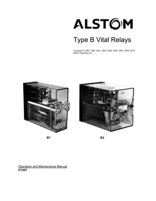
- 21. General Description 1. SECTION 1 – GENERAL DESCRIPTION 1.1. INTRODUCTION TO VITAL RELAYS For over 70 years, Alstom Signaling Inc. has continually perfected the Type B relays. They are the standard relay of the signaling industry. Types B and VTB plug-in relays meet applicable manual parts of American Railway Engineering and Maintenance of Way Association (AREMA). Alstom Type B plug-in relays are used in vital circuits, and are rack-installed in equipment rooms and in wayside cases and housings. These relays are divided into two sizes, B1 and B2, as shown in Figure 1–1. Some B relays are energized by DC voltage, others by AC voltage. A vital relay is designed so that the probability of its failing to return to a prescribed state when it is de-energized is so low that for all practical purposes it is considered to be nonexistent. ALS ALS B1 RELAY B2 RELAY Figure 1–1. Alstom Type B1 and Type B2 Type Vital Relays There are more than a dozen types of Type B relays, available in about 200 configurations. They are designed to meet the important requirements of safety, reliability, low maintenance and long operating life. Replacement parts for relays decades old may still be available should it become necessary to extend their operating life. Alstom furnishes its customers relay application and adjustment instructions, either as part of a contract or upon request. P1457, Rev. Apr/10 1–1 Alstom Signaling Inc.
- 22. General Description 1.2. RELAY CHARACTERISTICS AND COMPONENTS 1.2.1. Size Type B relays are made in two sizes, Size 1 and 2, and are referred to as B1 and B2 relays. Two Size 1 relays occupy the same space as one Size 2 relay. Additionally, there is a special size relay, Type VTB code-responsive, which occupies the plugboard space for a B2 relay, but is not the same depth. Table 1–1 provides exact sizes and weights. Table 1–1. Relay Sizes and Weights Dimensions and Weights Size 1 Size 2 VTB Height of relay 6-5/16 in. 6-5/16 in. 7-11/16 in. Width of relay 2-7/16 in. 4-15/16 in. 4-15/16 in. Depth without plugboard 8-9/16 in. 8-9/16 in. 6-7/16 in. Depth including plugboard fully wired 15-1/2 in. 15-1/2 in. 13-3/8 in. (approx.) Weight of relay with plugboard (weight of 7 to 10 lbs. 10 to 15 lbs. 6 to 7 lbs. wiring not included) Weight of plugboard alone without wiring 1 lb. 2 lbs. 2 lbs. P1457, Rev. Apr/10 1–2 Alstom Signaling Inc.
- 23. General Description 1.2.2. Identification All Type B relays carry nameplates that contain the drawing number (part number) and catalog number of the relay. Relay drawing number is also shown on the registration plates of the relay. When inquiring about a particular relay, always provide the catalog or drawing number. The drawing and catalog numbers can be used with the tables in Appendix A to look up the relay's Engineering Data (ED) Sheet number. The ED sheet contains technical specifications referenced during some maintenance procedures. Each B2 Relay has a Test Data Form on the cover and a name plate located inside the relay, visible through the front of the cover. Each B1 Relay cover contains two recesses to allow attachment of two metalized polyester film or mylar tags with permanent adhesive: • a tag for relay operating and testing data • a tag for circuit nomenclature B1 Relays manufactured prior to 1991 have a different cover than those relays manufactured after 1991. The most obvious difference is the handle on the front of the relay. B1 Relay nameplate, nametag and test data form locations for relays manufactured pre and post 1991 are shown in Figure 1–2. 2 PIECE METAL HANDLE PLASTIC HANDLE MOLDED TO COVER NAMEPLATE NAMETAG TEST DATA FORM PRE 1991 STYLE POST 1991 STYLE Figure 1–2. B1 Relay Nameplate, Nametag and Test Data Form P1457, Rev. Apr/10 1–3 Alstom Signaling Inc.
- 24. General Description The information provided on the test data form includes the relay serial number, data from the specification sheet for the relay, the initials of the Alstom employee who tested the relay, and the date the form was completed. An example B1 Relay test data form is shown in Figure 1–3. This example form includes the following: • Space 1 - The serial number as shown on relay nameplate. • Space 2 - The minimum DROP AWAY (D.A.) value from specification sheet in Amps for a DC relay or Volts for an AC relay. For example, on a 921-09 relay the space contains 0.077A for the minimum DROP AWAY. An "A" for Amps should be added or "VAC" for AC relays. • Space 3 - The maximum PICKUP (P.U.) value from specification sheet in the same style as in Space 2. • Space 4 - The maximum WORKING Current (W.C.) value from specification sheet in the same style as in Space 2. • Space 5 - The initials of the Alstom employee who tested the relay. • Space 6 - The date the form was completed in Month/Day/Year format (for example 7/26/94). SERIAL NO. 1 D.A.(MIN) 2 P.U. (MAX) 3 W.C. (MAX) 4 INSP. 5 DATE 6 Figure 1–3. Example B1 Relay Test Data Form P1457, Rev. Apr/10 1–4 Alstom Signaling Inc.
- 25. General Description 1.2.3. Relay Prongs and Plugboard All Type B relays plug onto plugboards. Relay contacts and coil(s) are brought out through the base of the relay as prongs. The plugboard has wedge shaped plug insulators. There are two terminals per insulator, one on each side. The terminals are installed from behind the plugboard. See Figure 1–4 for a simplified mating diagram. For exact dimensions, see Table 1–2. TOP TERMINAL RELAY CONTACT PLUGBOARD BLOCK WIRES TO RELAY WIRE HARNESS SPRINGS INSULATOR SLIDING CONTACT BOTTOM PRONGS TERMINAL Figure 1–4. Plug Connection Table 1–2. Plugboard Dimensions Dimension B1 B2 Overall Height 9-7/16 in. 9-7/16 in. Overall Width 2-1/2 in. 5 in. Overall Depth 10-1/2 in. 10-1/2 in. Diameter of mounting holes (clearance for 1/4 in. bolt) 9/32 in. 9/32 in. Vertical distance between centerlines of mounting holes 8-13/16 in. 8-13/16 in. There should be about a 5-inch clearance behind a plugboard to give room for wire distribution in a relay rack. P1457, Rev. Apr/10 1–5 Alstom Signaling Inc.
- 26. General Description When a relay is plugged in, two relay guide rods align the relay so that all prongs properly align with their corresponding insulators. The prongs slide onto their respective plugboard terminals, thus making contact. Figure 1–5 shows a B1 plugboard; including the location of the relay guide rods. Because plugboard terminals are connected to the wires in cables behind the plugboard, no wiring changes are necessary when replacing a Type B relay. TOP WIRE TERMINAL 16 26 36 36 26 16 6 INSULATOR 15 25 35 35 25 15 5 14 24 34 34 24 14 4 CONTACT BOTTOM 13 23 33 TERMINALS 33 23 13 3 WIRE 12 22 32 32 22 12 2 TERMINAL RELAY 11 21 31 31 21 11 1 GUIDE RODS 3 2 1 3A REGISTRATION 3A 3B COIL PLATE MALE TERMINALS 3B 3C 3C 3D 3D TEST TERMINALS 1E 3E 3E 1E FRONT VIEW REAR VIEW Figure 1–5. B1 Plugboard P1457, Rev. Apr/10 1–6 Alstom Signaling Inc.
- 27. General Description 1.2.4. Mounting The B relays plug on to plugboards. The contacts and the coil terminals of the relay protrude through the base of the relay as prongs. The plugboard has wedge-shaped plug insulators with flat metal terminals on the two faces of the wedge. Two rods guide a relay being plugged in, allowing the pairs of relay prongs to meet with corresponding wedges, spreading the prongs apart. The prongs slide onto the respective plugboard terminals making contact as shown in Figure 1–6. CONTACT BLOCK PLUGBOARD IN RELAY TERMINAL CONTACT PRONGS Figure 1–6. Type B Plug Connections P1457, Rev. Apr/10 1–7 Alstom Signaling Inc.
- 28. General Description 1.2.5. Registration Registration plates prevent plugging a relay into the wrong place in a rack or module. Figure 1–7 shows two registration plates, one with holes, the other with pins. The plate with holes is attached to the base of the relay. The plate with pins is attached to the plugboard. If a relay that does not belong on the plugboard should be slipped on the guide rods, it is prevented from making contact with the terminals in the plugboard because the registration pins and holes do not correspond with one another. 16 26 36 15 25 35 14 24 34 13 23 33 12 22 32 11 21 31 REGISTRATION 3A REGISTRATION REGISTRATION 3B FEMALE PLATE PLATE MALE FEMALE PLATE 3C 3D RELAY 1E 3E PLUGBOARD Figure 1–7. Registration Plates P1457, Rev. Apr/10 1–8 Alstom Signaling Inc.
- 29. General Description The registration feature takes care of six important differences in relays: • Differences in timing • Differences in contact arrangement • Differences in contact opening • Differences between track and line relays • Differences in coil resistance • Differences in coil arrangement 1.2.6. Insulators Insulators are made of molded plastic and fit into slots in the plugboard. Each insulator is held in place by a locking latch molded into a spring beam on one side of the insulator as shown in Figure 1–8. An extractor tool must be used to remove the terminals prior to removing the insulators. To release the insulator so that it can be pulled out of the plugboard, squeeze the spring beam and push the insulator towards the front of the plugboard. There are 11 insulators in a B1 plugboard and up to 20 in a B2 plugboard. PLUGBOARD SPRING BEAM SQUEEZE TOWARDS INSULATOR TO RELEASE INSULATOR INSULATORS CRIMP WIRES TO TERMINAL CONNECTIONS EXTRACTOR Figure 1–8. Latching Insulator NOTE An integral beam latch secures the insulator to the plugboard. P1457, Rev. Apr/10 1–9 Alstom Signaling Inc.
- 30. General Description 1.2.7. Terminals B relay plugboards contain contact terminals, coil terminals and test terminals as shown in Figure 1–5. There are two types of terminals, solder terminals and crimp terminals. Refer to Section 3, Installation, for installation supplies. 1.2.7.1. Contact Terminals There are two contact terminals per insulator, one on the top and one on the bottom as shown in Figure 1–9. Each terminal is completely insulated from the adjacent one, by either the insulator or the wall of plastic material that surrounds each insulator and terminal assembly. L INA RM YPE) E T PT TO LDER RELAY CONTACT END (SO T OR LA SU AL IN IN ) RM YPE TE T OP IMP T R (C L NA MI E) R P TE O M R TY TT D E WIRE CONNECTOR END BO SOL ( L NA RMI ) TE YPE OM P T TT I M B O (C R Figure 1–9. Insulator Separates One Contact Terminal From the Other The terminal slips into place from behind the plugboard. First, the wire is connected to the terminal; then the terminal is pushed into the proper slot in the plugboard. On B1 plugboards, there are slots for 18 contact terminals for circuits through relay contacts and 4 for circuits through the coils. On B2 plugboards, there are slots for 36 contact terminals and 4 coil terminals. P1457, Rev. Apr/10 1–10 Alstom Signaling Inc.
- 31. General Description 1.2.7.2. Test Terminals A current test terminal is provided on the plugboard directly under the relay, as shown in Figure 1–10, to allow the checking of current flow through the relay coils. NOTE Not all relay plugboards are equipped with a current and voltage test terminal. FRONT TO CABLE PLUGBOARD HALF HARNESS NUT B2 INSULATING PLUGBOARD BUSHING 1E 6E TERMINAL POST SPANNER NUT B1 COPPER TO RELAY PLUGBOARD STRAP COIL TERMINAL 1E 3E CURRENT TEST CURRENT TEST TERMINAL TERMINALS CIRCUIT SYMBOL Figure 1–10. Current Test Terminal A voltage test terminal is provided on the plugboard next to the current test terminal, as shown in Figure 1–11, to allow the checking of voltage across the relay coils. FRONT TO CABLE B2 PLUGBOARD HARNESS 1E 6E TO COIL TERMINAL B1 PLUGBOARD 1E 3E VOLTAGE TEST TERMINAL VOLTAGE TEST CIRCUIT SYMBOL TERMINAL Figure 1–11. Voltage Test Terminal P1457, Rev. Apr/10 1–11 Alstom Signaling Inc.
- 32. General Description 1.2.7.3. Numbering of Contacts and Plugboard Terminals From the front of the relay, the vertical columns of contacts and their plugboard terminals are numbered 1, 2, 3, etc. from left to right. The contact springs in each row are numbered from bottom to top 1, 2, 3, etc. These numbers are molded into the plugboard adjacent to the slots. Thus, all contact terminal numbers contain two digits, as shown in Figures 1–12 and 1–13. The first digit indicates the column; the second indicates the row. For example, terminal 36 is the third column from the left, sixth row from the bottom. The terminal 23 is the second column from the left, third row from the bottom. Only the springs with contacts are numbered. The stops and pressure plate springs are not numbered. 16 26 36 36 26 16 6 15 25 35 35 25 15 5 14 24 34 34 24 14 4 13 23 33 33 23 13 3 12 22 32 32 22 12 2 11 21 31 31 21 11 1 3 2 1 3A REGISTRATION 3A 3B PLATE MALE 3B 3C 3C 3D 3D 1E 3E 3E 1E FRONT VIEW REAR VIEW Figure 1–12. Terminal Numbering of Type B, Size 1 (B1) DC Relays P1457, Rev. Apr/10 1–12 Alstom Signaling Inc.
- 33. General Description 16 26 36 46 56 66 66 56 46 36 26 16 15 25 35 45 55 65 65 55 45 35 25 15 14 24 34 44 54 64 64 54 44 34 24 14 13 23 33 43 53 63 63 53 43 33 23 13 12 22 32 42 52 62 62 52 42 32 22 12 11 21 31 41 51 REGISTRATION 61 61 51 41 31 21 11 PLATE MALE 6C 1C 1C 6C 1D 6D 6D 1D 1E 3E 4E 6E 6E 4E 3E 1E FRONT VIEW REAR VIEW Figure 1–13. Terminal Numbering of Type B, Size 2 (B2) DC Relays P1457, Rev. Apr/10 1–13 Alstom Signaling Inc.
- 34. General Description 1.2.8. Guide Rods Two guide rods, which extend from the face of the plugboard 8-1/2 inches, help guide the relay into alignment with the insulators on the plugboard. Each rod has a knurled nut and a lock nut to secure the relay on its plugboard, as shown in Figure 1–14. LOCK NUTS KNURLED NUTS GUIDE RODS Figure 1–14. B1 Relay showing Guide Rods and Nuts 1.2.9. Wiring Wires strapped together in cable form are supported behind the plugboard. Each wire is identified with a tag and then connected to its terminal. The terminal is pushed into its slot in the plugboard and locked in place. The plugboard back can accommodate the mounting of a two-post terminal block as shown in Figure 1–16. This can be used to terminate coil leads where coils in a relay are circuited independent of one another. P1457, Rev. Apr/10 1–14 Alstom Signaling Inc.
- 35. General Description 1.2.10. Relay Contacts Relays are furnished with specific contact arrangements. In all relays, the contacts are leaf springs molded in blocks. Each block is called a contact group. One end of the spring is formed into a prong, which makes contact with the plugboard terminal. The other end has a contact. Figure 1–15 shows a typical configuration of the relay contact components. PRESSURE PLATE PLUGBOARD FRONT CONTACTS CONTACT STOP HEEL PLATE Figure 1–15. Relay Contact Components 1.2.11. Coils On B1 and B2 DC relays, there is space enough on each of the two cores for one full- length coil, approximately 4 inches long. Coils shorter than this are used when the cores are partly filled with copper or aluminum washers or slugs for use in slow-acting relays. 1.2.11.1. Identifying Coil Leads The two leads of a coil are designated as "in" and "out" leads. From the prong end of a coil, the IN lead is attached to the prong that is closer to the center of the coil. The OUT lead is attached to the prong furthest from the center. If a coil has two windings, the winding nearer the prongs is connected to the prongs. Leads of the second winding are tagged and have terminals applied. P1457, Rev. Apr/10 1–15 Alstom Signaling Inc.
- 36. General Description 1.2.11.2. Numbering of Coil Terminals Two digit coil terminal identifiers consisting of a number and a letter are molded in the phenolic plugboard. The number is taken from the vertical row in which the terminal is located. The letter shows its position in that row. Letter A is given to the highest terminal, letter D to the lowest terminal for B relays. Letter E is use to designate test terminals. See Figure 1–16. 3A 1C SPARE TERMINAL COIL 3B BLOCK TERMINALS 3C (P/N 46048-053-01) 6C 1C IF SO EQUIPPED COIL TERMINALS 3D 6D 1D 1D TEST TEST TERMINALS TERMINALS 3E 1E 6E 1E B1 B2 Figure 1–16. Coil Terminal Numbers, B1 and B2 Relay (Rear View) P1457, Rev. Apr/10 1–16 Alstom Signaling Inc.
- 37. Theory of Operation 2. SECTION 2 – THEORY OF OPERATION 2.1. GENERAL This section covers the functions of Alstom Type B relays. B relays contain various arrangements of contacts and coils. Information is presented as follows: • Relay Contacts and Coils • B1 Relays • B2 Relays Figure 2–1 identifies typical B1 Relay components. Some type B2 Relays look very similar to the typical B1 Relay shown, others do not. See the B2 Relay discussions for relay descriptions. P1457, Rev. Apr/10 2–1 Alstom Signaling Inc.
- 38. Theory of Operation COMPRESSION SPRING CONTACT PRONGS COVER BASE COIL SPRING STUD CONTACT GROUP ARMATURE STOP SCREW PRESSURE PLATES BRIDGE OR ARM. EXTENSION STOP PLATES PUSHER PUSHER JAW BACK CONTACT PUSHER RETAINING CLIPS HEEL CONTACT ROLLER ON FINGER FRONT CONTACT ADJ. NUT ARMATURE LOCK NUT ARMATURE RETAINING PLATE YOKE PRONGS NUT COIL COIL ARMATURE BEARING PLATE REGISTRATION NAME PLATE PLATES SAFETY PIN ADJUSTABLE RESIDUAL SCREW CORE NOTE: SOME PARTS MAY DIFFER IN DETAIL FROM THOSE SHOWN ABOVE BUT NAME DESIGNATION REMAINS THE SAME. Figure 2–1. Typical B1 Relay Components P1457, Rev. Apr/10 2–2 Alstom Signaling Inc.
- 39. Theory of Operation 2.2. RELAY CONTACTS AND COILS 2.2.1. Definitions The following terms are used in the descriptions of how relay contacts operate: • Front -Relay contact that is open when relay is de-energized. • Heel - Contact that is driven by pusher. • Back - Relay contact that is made when relay is de-energized (normally closed). • Make - Specified dimension that will cause all front or back contacts to be just made (closed) when a gauge of the specific dimension is inserted between the armature residual screw and core face with the relay energized. • Break - All front or back contacts are just open when a gauge of a specific dimension is inserted between the armature residual screw and the core face with the relay de- energized. • Break-before-make - In a dependent front-heel-back contact, the back contact will break before the front contact makes as the relay is energized. • Makes-before-break - In a dependent front-heel-back contact, the front contact will make before the back contact breaks. A complete glossary of terms used in this manual is available in Appendix B. 2.2.2. Contact Groups There are typically six springs per contact group, furnished in various combinations of contacts. The AC Vane Relay contact groups contain four springs. Springs are furnished for each group in various combinations of contacts. For example, a contact group can have two dependent front-back (FB) contacts or three independent contacts (front or back). • A dependent FB contact uses three springs, one for the stationary front (F), one for the stationary back (B), and one for the movable heel. • An independent contact uses two springs, one for the stationary contact (front or back), and one for the movable heel. P1457, Rev. Apr/10 2–3 Alstom Signaling Inc.
- 40. Theory of Operation The relay armature, as shown in Figure 2–2, has a bridge attached to it, which engages a pusher. The pusher engages a roller on the heel contact to move the heel contact up or down in response to the movement of the relay armature. HEEL CONTACT ROLLER ARMATURE BRIDGE PUSHER Figure 2–2. Heel Contact Engaging Pusher Typical contact groups are shown in Figure 2–3. 2 Front-Back (FB) Dependent Contacts 1 Front (F) 2 Back (B) Independent Contacts 3 Back (B) Independent Contacts Figure 2–3. Three Different Contact Combinations P1457, Rev. Apr/10 2–4 Alstom Signaling Inc.
- 41. Theory of Operation 2.2.2.1. Contact Combinations A B1 Relay has space for three contact groups. For example, a relay with 6 front-back dependent contacts has three groups, each with 2 front-back contacts. A relay with 4 front-back dependent contacts and 2 front and 1 back independent contacts also has three groups, two with 2 front-back dependent contacts, and one with 2 front and 1 back independent contacts. A typical B2 Relay has space for six contact groups. For example, a relay with 12 front- back contacts has six groups, each with 2 front-back contacts. The B2 AC Vane Relay has a different configuration with space for four contact groups. Table 2–1 shows the contact combinations normally furnished with B relays. For the configuration of specific arrangements, see Section 7. Table 2–1. Typical Relay Contact Combinations Type B1 Relays B2 Relays B2 Vane Relays (3 Contact Groups) (6 Contact Groups) (4 Contact Groups) Neutral 2FB, 4FB, 4F-2B, 12FB 4FB-2F-1B, 6FB Biased-Neutral 4FB-2F-1B, 6FB 8FB-4F-2B, 12FB Magnetic-Stick 4 NR Power-Transfer 2FB, 6FB Light-Out 4FB, 4F-2B, 6FB AC Vane 2FB, 4FB FB Front-Back Dependent Contact F Front Independent Contact B Back Independent Contact NR Normal-Reverse Dependent Contact P1457, Rev. Apr/10 2–5 Alstom Signaling Inc.
- 42. Theory of Operation 2.2.2.2. Regular Contacts Contacts for regular service are rated for a resistance load of 4 amperes continuously. Front contacts are silver-impregnated-carbon to silver; back contacts are silver to silver. See Figures 2–4 and 2–5. FRONT CONTACT SILVER IMPREGNATED CARBON HEEL SILVER BACK CONTACT SILVER Figure 2–4. 2 Front (F) and 1 Back (B) Independent Regular Contacts Figure 2–5. 2 Front-Back (FB) Dependent Regular Contacts P1457, Rev. Apr/10 2–6 Alstom Signaling Inc.
- 43. Theory of Operation 2.2.2.3. Heavy-Duty Contacts Heavy-duty contacts, shown in Figure 2–6, are commonly used in circuits of the first and second voltage ranges where the continuous resistive load current is more than four amperes. The first voltage range is 30 volts or less; the second voltage range is over 30 volts to 175 volts inclusive. Front contacts are usually Silver-Impregnated-Carbon to Silver; back contacts are Silver to Silver. For the rating of contacts on relays containing heavy-duty (HD) contacts consult the specific relay's Engineering Data (ED) sheet. Figure 2–6. 2 Front-Back (FB) Dependent Heavy-Duty Contacts P1457, Rev. Apr/10 2–7 Alstom Signaling Inc.
- 44. Theory of Operation 2.2.2.4. Contacts with Magnetic Blowouts Heavy-duty contacts equipped with magnetic blowouts, shown in Figure 2–7, are generally used in d-c circuits carrying inductive loads where the continuous current is more than four amperes and where operation is in the second or third voltage ranges. The third voltage range is over 175 volts to 250 volts inclusive. For the rating of contacts on relays containing heavy-duty contacts with blowout magnets (XHD) consult the specific relay's Engineering Data (ED) sheet. MAGNETIC BLOWOUT MAGNETIC BLOWOUT Figure 2–7. One Front and One Back Independent Heavy-Duty Contacts with Magnetic Blowouts Both front and back contacts are the heavy-duty type just described. Magnets are held in clips close to the contacts. The effect is to "blow" or disperse the electric arc before it has a chance to grow and burn. The front contact opening is usually 0.125” minimum for this type of contact. Using magnetic blowout contacts sacrifices the space of one contact group in the relay. P1457, Rev. Apr/10 2–8 Alstom Signaling Inc.
- 45. Theory of Operation 2.2.3. Coils A coil may be made up of one or more separate windings, leads from these windings being fastened to prongs that engage with the plugboard terminals or to terminals that go on a binding post within the relay. See Figures 2–8 and 2–9. A typical coil is wound on a phenolic spool that slips over one core of the relay. Every coil is identified with its drawing number and nominal resistance. IN T WINDING DIAGRAM IN OU OUT CAP REMOVED CAP Figure 2–8. Coil Construction, One Winding "IN" FOR "B" WINDING "A" "B" "IN" FOR "A" WINDING "OUT" FOR "A" WINDING "OUT" FOR "B" WINDING WINDING DIAGRAM "A" "B" WINDING WINDING CAP T IN OU LEADS FOR "B" WDG. CAP REMOVED Figure 2–9. Coil Construction, Two Windings P1457, Rev. Apr/10 2–9 Alstom Signaling Inc.
- 46. Theory of Operation 2.2.3.1. One-Coil Relays (Slow Acting Relays) One core of a relay can be completely filled with copper washers or a slug of aluminum or copper to make the relay slow acting. In this case, only one coil is used to operate the relay. The more washers used, or the longer the slug, the slower the relay operates. If the relay is to be slightly slow acting, short coils on the cores usually provide enough room for the required number of washers or a short slug. If the relay is to be slower acting, one coil is put on the lower core and a slug is put on the upper core. The circuit of a one-coil B1 Relay is shown in Table 2–2 (3A and 3B). The IN lead of the coil is connected to the 3C terminal on the plugboard; the OUT lead is connected to the 3D terminal. Positive energy is applied through the current test terminal 3E to terminal 3C. The circuit for a one-coil B2 Relay is shown in Table 2–2 (3A and 3B). The IN lead of the coil is in contact with the 6C terminal on the plugboard; the OUT lead contacts the 6D terminal. Positive energy is applied through the current test terminal 6E to terminal 6C. B2 Neutral Relays with slugs are rarely used, as there is seldom the need for B2 Slow- Release Relays with such large contact capacity. 2.2.3.2. Two-Coil Relays In two-coil B1 Relays, the upper coil plugs onto terminals 3A and 3B of the plugboard, the lower coil onto terminals 3C and 3D. Connections between the coils are made on the back of the plugboard for series, parallel, or single coil operation. The circuits in Table 2–2 show these possibilities. In two-coil B2 Relays, from the front of the relay, the left-hand coil plugs onto terminals 1C and 1D, the right-hand coil onto terminals 6C and 6D. See Table 2–2 for a brief explanation of circuit description, timing characteristics and application notes. P1457, Rev. Apr/10 2–10 Alstom Signaling Inc.
- 47. P1457, Rev. Oct/08 Table 2–2. Coil Connections and Timing Characteristics Circuit Circuit Timing Notes B1 Relay B2 Relay Description Characteristics 1 Series Pickup normal I = WORKING current E = 2 RI – R Release normal R = resistance of one coil I 1C 1D + – 3A R 3B 6D R 6C 6E E = voltage required to get 3D R 3C 3E + full pressure on the front contact 2 Multiple Pickup fast Voltage across coils is one E = (1/2r)(2I) Release normal half (1/2) the voltage across 2I the coils of item 1 above Theory of Operation – r – r 1C 1D 3A 3B r + r + 6D 6C 3D 3C 6E 3E 2–11 3A One coil Release slow: up Timing is affected when separating slugs to as high as controlled over line because – + – + 3D 3C 3E 6D 6C 6E on other core three (3) seconds of line drop 3B One coil Pickup slow: up Timing is affected when separating slugs to as high as controlled over line because – 3D 3C 3E + – 6D 6C 6E + on other core three (3) seconds of line drop 4 Series with Pickup normal Do not use in circuits rectifier shunted Release slow, subject to lightning – – across coils but less slow Do not energize from a ALSTOM Signaling Inc. 3A 3B 1C 1D + + 3D 3C 3E 6D 6C 6E than 3A or 3B battery whose other circuits are subject to lightning
- 48. P1457, Rev. Oct/08 Table 2–2. Coil Connections and Timing Characteristics (Cont.) Circuit Circuit Timing Notes B1 Relay B2 Relay Description Characteristics 5 Multiple with Pickup fast Do not use in circuits rectifier shunted Release slow, subject to lightning across coils but less slow – – 3A 3B 1C 1D 3D 3C 3E + 6D 6C 6E + than 4 6 One coil Pickup slow Shunt should be applied to – + – + operating, one Release slow, the lower coil of B1 Relays 3A 3B 3E 6D 6C 3D 3C 1C 1D 6E coil shunted but less slow to get the maximum slow than 4 release effect Theory of Operation 7 One coil Pickup normal 2–12 – 3A 3B + – 6D 6C + operating, one Release slow, 3E 6E 3D 3C 1C 1D coil shunted but less slow when armature than 3A, 3B, or 4 is picked up 8 Series with Pickup normal The lower the resistor, the resistor shunted Release slow, slower the relay; takes more across coils but less slow current, will therefore affect – – 3A 3B + 1C 1D + than 3A, 3B, or 4 operation of any relays in 3D 3C 6D 6C 3E 6E series 9 Series with Pickup normal The greater the capacity of ALSTOM Signaling Inc. resistor and Release slow, the capacitor, the slower the capacitor slower than 3A or relay; a resistor should – – 3A 3B + 1C 1D + shunted across 3B, up to ten (10) always be used in series in 3D 3C 6D 6C 3E 6E coils seconds case the capacitor shorts
- 49. Theory of Operation 2.3. BIASED-NEUTRAL TRACK RELAYS All Biased-Neutral Track Relays (B1 and B2) have normal pickup and release timing characteristics. Figures 2–10 and 2–11 illustrate typical B1 Biased-Neutral Relays. Figure 2–10. Type B1 Biased-Neutral Relay, Pre-1991 Cover Figure 2–11. Type B1 Biased-Neutral Relay, Post-1991 Cover P1457, Rev. Apr/10 2–13 Alstom Signaling Inc.
- 50. Theory of Operation Figure 2–12 shows typical B1 Relay wiring. 2 WINDINGS IN PARALLEL (FRONT VIEW) 16 26 36 15 25 35 14 24 34 13 23 33 12 22 32 11 21 31 3A (-) UPPER COIL I 3B 1E O 3C PLUGBOARD JUMPERS LOWER COIL I (+) TO PARALLEL COILS 3D 3E O THICK WIRING IS PLUGBOARD WIRING. THIN WIRING IS RELAY WIRING. I ="IN" LEAD O = "OUT" LEAD Figure 2–12. Typical B1 Track Relay Wiring Another application of the biased-neutral function is in the DC high percentage release track relay that can be used in track circuits up to 20,000 feet long. With its low nominal resistance of 0.5 ohm (with coils connected in parallel), this B1 Relay provides fast, high shunting sensitivity under poor ballast conditions while giving excellent protection against foreign current. In addition, this relay will not pick up when 50 times reverse polarity WORKING current is applied. The operation of a biased neutral line relay is discussed under Heading 2.4.2. P1457, Rev. Apr/10 2–14 Alstom Signaling Inc.