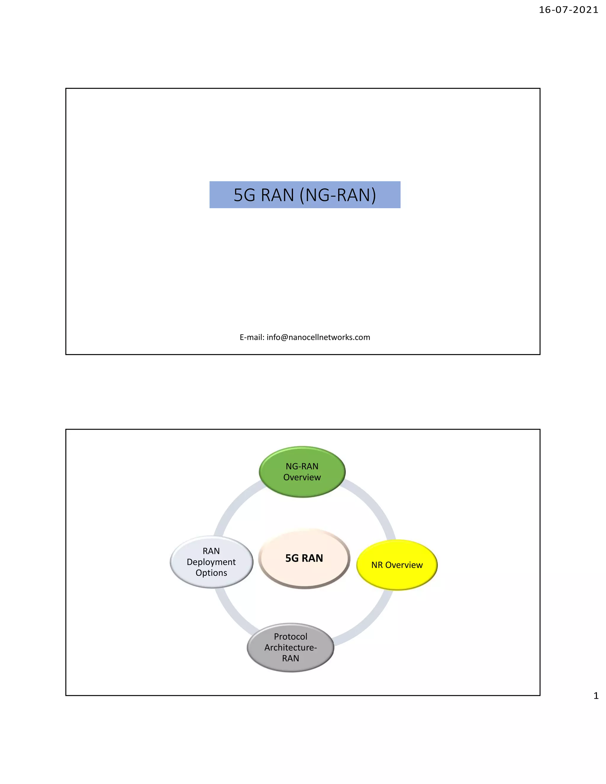
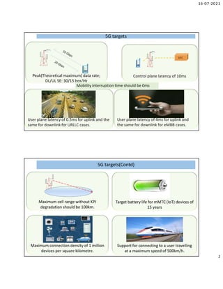
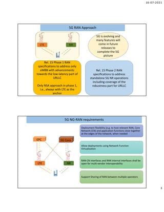
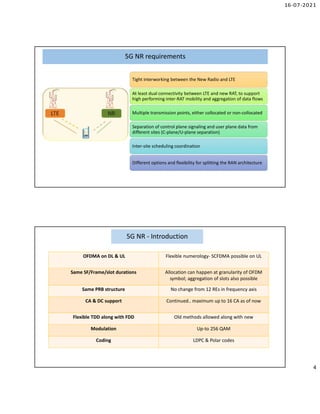
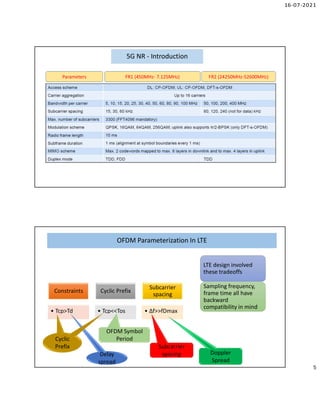
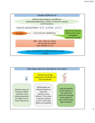
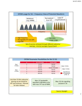
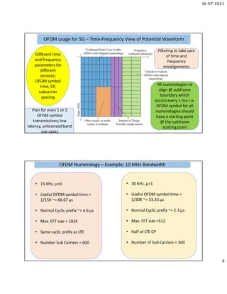
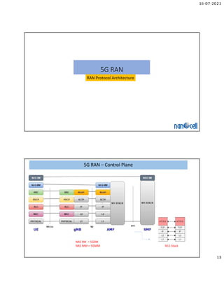
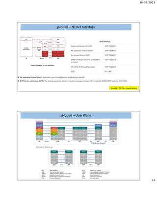
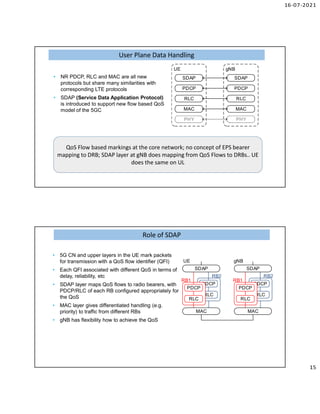
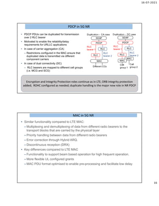
16-07-2021
1
5G RAN (NG-RAN)
E-mail: info@nanocellnetworks.com
5G RAN
NG-RAN
Overview
NR Overview
Protocol
Architecture-
RAN
RAN
Deployment
Options
16-07-2021
2
5G targets
5G targets
Peak(Theoretical maximum) data rate;
DL/UL SE: 30/15 bps/Hz
EPC
Control plane latency of 10ms
User plane latency of 0.5ms for uplink and the
same for downlink for URLLC cases.
User plane latency of 4ms for uplink and
the same for downlink for eMBB cases.
Mobility interruption time should be 0ms
5G targets(Contd)
5G targets(Contd)
Maximum cell range without KPI
degradation should be 100km.
Target battery life for mMTC (IoT) devices of
15 years
Maximum connection density of 1 million
devices per square kilometre.
Support for connecting to a user travelling
at a maximum speed of 500km/h.
16-07-2021
3
5G RAN Approach
5G RAN Approach
LTE NR
Rel. 15 Phase 1 RAN
specifications to address only
eMBB with advancements
towards the low-latency part of
URLLC
Only NSA approach in phase 1,
i.e., always with LTE as the
anchor
Rel. 15 Phase 2 RAN
specifications to address
standalone 5G NR operations
including coverage of the
robustness part for URLLC
5G is evolving and
many features will
come in future
releases to
complete the 5G
picture
5G NG-RAN requirements
LTE NR
EPC 5G Core
Deployment flexibility (e.g. to host relevant RAN, Core
Network (CN) and application functions close together
at the edges of the network, when needed
Allow deployments using Network Function
Virtualization
RAN-CN interfaces and RAN internal interfaces shall be
open for multi-vendor interoperability
Support Sharing of RAN between multiple operators
16-07-2021
4
5G NR requirements
5G NR requirements
LTE NR
Tight interworking between the New Radio and LTE
At least dual connectivity between LTE and new RAT, to support
high performing inter-RAT mobility and aggregation of data flows
Multiple transmission points, either collocated or non-collocated
Separation of control plane signaling and user plane data from
different sites (C-plane/U-plane separation)
Inter-site scheduling coordination
Different options and flexibility for splitting the RAN architecture
5G NR - Introduction
OFDMA on DL & UL Flexible numerology- SCFDMA possible on UL
Same SF/Frame/slot durations Allocation can happen at granularity of OFDM
symbol; aggregation of slots also possible
Same PRB structure No change from 12 REs in frequency axis
CA & DC support Continued.. maximum up to 16 CA as of now
Flexible TDD along with FDD Old methods allowed along with new
Modulation Up-to 256 QAM
Coding LDPC & Polar codes
16-07-2021
5
5G NR - Introduction
Parameters FR1 (450MHz- 7.125MHz) FR2 (24250MHz-52600MHz)
OFDM Parameterization In LTE
Constraints
• Tcp>Td
Cyclic Prefix
• Tcp<<Tos
Subcarrier
spacing
• ∆f>>fDmax
LTE design involved
these tradeoffs
Sampling frequency,
frame time all have
backward
compatibility in mind
Delay
spread
Cyclic
Prefix
OFDM Symbol
Period
Subcarrier
spacing Doppler
Spread
16-07-2021
6
Flexible OFDM for 5G
Subcarrier spacing (Flexible) = f0* 2µ, f0=15 kHz, µ=-2,…5
3.75k (15K) ≤∆f< (240)480 kHz
BWs: Min: 5 MHz for f<6GHz
Min 50 MHz for f>6GHz
Max. 400 MHz in R 15
IoT cases
Used in mm wave for
higher phase noise;
manageable
subcarrier spacings
Why is this flexibility in OFDM parameters needed
for 5G?
Different Numerology to suit different
bandwidths/applications; Combo. of subcarrier spacing
and CP durations
Why large subcarrier spacings for mm-wave?
Potential use of high
frequencies; 26-28 GHz, 39
GHz,and beyond
Absolute values of
frequency offsets
and phase noise
related parameters
are higher than in
lower frequencies
OFDM signals are
affected relative to
subcarrier
spacing..in freq.
domain.. If the same
subcarrier spacing
as LTE is used, then
effects are amplified
Large bandwidths
are the big plus in
mm-wave; low
subcarrier spacings
means large FFT
sizes; which implies
high complexity
16-07-2021
7
OFDM usage for 5G – Frequency View of Potential Waveform
Frequency
Wideband
(e.g. eMBB)
Narrowband
(e.g. IoT)
Large CP
(e.g.Broadcast)
• High frequency
• Manageable FFT size with
large BW
• Sub 1GHz
• Longer range
Mix of services achieved through different subcarrier
spacings; minimal wastage of guard band
OFDM Parameter Possibilities for Rel 15 5G
Less than 15 KHz subcarrier
spacing can be handy for
IOT and multicast.. Planned
for later releases
Max. CC bandwidth
specified is 400 MHz so far
with max. FFT size of 4096
Max. CCs for signalling
purpose is 16
Source: Keysight
16-07-2021
8
OFDM usage for 5G – Time-Frequency View of Potential Waveform
Different time
and frequency
parameters for
different
services;
OFDM symbol
time, CP,
subcarrier
spacing
Filtering to take care
of time and
frequency
misalignments
All numerologies to
align @ subframe
boundary which
occurs every 1 ms; i.e.
OFDM symbol for all
numerologies should
have a starting point
@ the subframe
starting point
Plan for even 1 or 2
OFDM symbol
transmissions; low
latency, unlicensed band
use cases
OFDM Numerology – Example; 10 MHz Bandwidth
• 15 KHz, µ=0
• Useful OFDM symbol time =
1/15K ~= 66.67 µs
• Normal Cyclic prefix ~= 4.6 µs
• Max. FFT size = 1024
• Same cyclic prefix as LTE
• Number Sub Carriers = 600
• 30 KHz, µ=1
• Useful OFDM symbol time =
1/30K ~= 33.33 µs
• Normal Cyclic prefix ~= 2.3 µs
• Max. FFT size =512
• Half of LTE CP
• Number of Sub Carriers = 300
16-07-2021
9
OFDM Numerology in visual form
Alignment of OFDM
symbol boundaries at
1 ms
Except for the first
OFDM symbol, the
rest have the same
length
This example has considered a
4096 FFT in different
bandwidths
OFDM Numerology – Numerology points
• µ gives the subcarrier spacing used; useful OFDM symbol time and cyclic prefix
fixed (option to have extended CP in some cases)
• FFT size depends on the bandwidth; sampling rate for calculation is fixed with
bandwidth; max. FFT sizes and bandwidths are specified in the standard
• Same bandwidth can have different subcarrier spacings; OFDM symbol duration
and CP duration are different; implications for handling delay spread
• Integer relationships between the OFDM symbol periods of different numerologies;
easier coexistence even in the same time interval
• Multiple numerologies give choices for handling different application; Different
parts of a larger channel bandwidth could have different numerologies
16-07-2021
10
5G NR- Better spectral utilization than LTE
Source : Nokia
5G PRBs and different numerology
# of PRBs in a given
bandwidth
depends on the
numerology
chosen
• 15 KHz -16 PRBs
• 30 KHz – 8 PRBs
• 60 KHz – 4 PRBs
• 120 KHz- 2 PRBs
gNB can mix
numerologies
in a DL
transmission
and schedule
in an UL
transmission
16-07-2021
11
5G NR Frame Structure
Slot is the more
important time unit
from a scheduling
perspective; smaller
slots useful for
handling low latency
applications
Source: 5G Book
5G NR Frame Structure
Source: Keysight
Same frame structure irrespective of FDD or
TDD or unlicensed operation
16-07-2021
12
5G Numerology Implications on various parameters
UE is not expected to be
able to receive in
different numerologies
at the same time in R 15
gNB can use different
numerologies to
different users in the
same slot
Inter user interference
due to different
numerologies has to be
taken care of
5G NR Flexibility ..in numbers
http://niviuk.free.fr/store_nr.php
16-07-2021
13
5G RAN
RAN Protocol Architecture
5G RAN – Control Plane
N11 Stack
NAS SM = 5GSM
NAS MM = 5GMM
16-07-2021
14
gNodeB – N1/N2 Interface
Source: GL Communications
gNodeB – User Plane
gNodeB – User Plane
16-07-2021
15
• NR PDCP, RLC and MAC are all new
protocols but share many similarities with
corresponding LTE protocols
• SDAP (Service Data Application Protocol)
is introduced to support new flow based QoS
model of the 5GC
gNB
PHY
UE
PHY
MAC
RLC
MAC
PDCP
PDCP
RLC
SDAP
SDAP
User Plane Data Handling
QoS Flow based markings at the core network; no concept of EPS bearer
mapping to DRB; SDAP layer at gNB does mapping from QoS Flows to DRBs.. UE
does the same on UL
• 5G CN and upper layers in the UE mark packets
for transmission with a QoS flow identifier (QFI)
• Each QFI associated with different QoS in terms of
delay, reliability, etc
• SDAP layer maps QoS flows to radio bearers, with
PDCP/RLC of each RB configured appropriately for
the QoS
• MAC layer gives differentiated handling (e.g.
priority) to traffic from different RBs
• gNB has flexibility how to achieve the QoS
RLC
PDCP
UE
MAC
SDAP
PDCP
RB1
RB2
RLC
PDCP
gNB
MAC
SDAP
PDCP
RB1
RB2
RLC RLC
Role of SDAP
Role of SDAP
16-07-2021
16
• PDCP PDUs can be duplicated for transmission
over 2 RLC bearer
• Motivated to enable the reliability/delay
requirements for URLLC applications
• In case of carrier aggregation (CA)
– Restrictions configured in the MAC ensure that
duplicated data is transmitted via different
component carriers
• In case of dual connectivity (DC)
– RLC bearers are mapped to different cell groups
(i.e. MCG and SCG)
RLC
MAC
SDAP
PDCP
RLC
bearer 2
RLC
RLC
bearer 1 RLC
SDAP
PDCP
RLC
bearer 2
RLC
RLC
bearer 1
MAC
MAC
Different CCs
Cell
group 1
Cell
group 2
Duplication - CA case Duplication - DC case
PDCP in 5G NR
PDCP in 5G NR
Encryption and Integrity Protection roles continue as in LTE; DRB integrity protection
added; ROHC configured as needed; duplicate handling is the major new role in NR PDCP
MAC in 5G NR
MAC in 5G NR
• Similar functionality compared to LTE MAC:
– Multiplexing and demultiplexing of data from different radio bearers to the
transport blocks that are carried by the physical layer
– Priority handling between data from different radio bearers
– Error correction through Hybrid ARQ.
– Discontinuous reception (DRX)
• Key differences compared to LTE MAC
– Functionality to support beam based operation for high frequent operation.
– More flexible UL configured grants
– MAC PDU format optimised to enable pre-processing and facilitate low delay
16-07-2021
17
• Beam failure detection and recovery
– UE Phy layer monitors beam failure detection (BFD) reference signals to
determine a beam failure
– On beam failure detection the UE MAC layer initiates beam failure recovery
– Selects a suitable beam on which to attempt recovery
– Performs random access procedure
• Beam management
– Mobility between beams is performed by a combination of Phy and MAC
signalling
– RRC signalling involved only to provide a measurement configuration (e.g.
configuration of the reference signals to be measured, etc)
MAC in 5G NR – Support for beamforming
gNodeB – C/U Plane
gNodeB – C/U Plane
Source: rcf-wireless
16-07-2021
18
E1
gNB-DU
gNB-CU-CP
F1-C F1-U
gNB
gNB-CU-UP
gNB-DU
gNB Control and User plane Split – Multi DU-CU
Flexibility in handling
control and user plane;
more flexibility in building
a small cell
Each gNB-DU can in turn
support multiple cells
Can mixing and matching
products in the RAN work?..
Can virtualized software implementation
of some RAN functions meet
performance requirements?
5G RAN
RAN Deployment Options
16-07-2021
19
5G Architecture Options
EPC Next Gen Core
LTE
NR
Many options
for integrating
LTE and 5G
system being
discussed
Non-standalone 5G
i.e., using LTE control
plane is likely to be
the first version
EUTRAN-NR Dual
Connectivity (EN-DC)
likely to be popular in
the initial deployments
5G Deployment Options
• There are mainly six
deployment options in
both SA and NSA
modes.
• Option-5 using 5GC
and LTE ng-eNB access
• Option-3 using EPC
and LTE eNB acting as
master and NR en-
gNB acting as
secondary;
• Option-4 using 5GC
and an NR gNB acting
as master and LTE ng-
eNB acting as
secondary
Source: GSMA
SA
NSA
• Option-7 using 5GC and an LTE ng-eNB acting as master
and an NR gNB acting as secondary.
16-07-2021
20
5G Architecture – First Deployments .. Some options
Source: GTI
Big load on LTE eNB
to handle all 5G
traffic along with
demands on X2
Can split traffic
between 5G and LTE
depending on
coverage.. Lighter
effect on X2
Master Cell
Group (MCG)
and Secondary
Cell Group
(SCG) Bearers
5G Architecture – EN-DC
Source: Rohde and Schwarz
MN is LTE eNB responsible for NAS connection,
handover etc.
16-07-2021
21
Operator Evolution Path – Option 1 (NSA Based)
Source: Nokia
Bring in 5G core network and
use 5G NR to offer the full
power of 5G to verticals while
keeping NSA option for legacy
devices
Upgrade to option 4 would
allow full fledged 5G offerings
with eLTE as an secondary
node; important to have good
5G coverage for this
Delays need for eLTE
Operator Evolution Path – Option 2 (NSA Based)
Source: Nokia
Upgrade to option 5 would allow 5G core
network services for eLTE; option 7x becomes
useful when LTE spectrum has wide coverage
Can get low-band NR carrier later in
the deployment; LTE/eLTE can
maintain coverage
16-07-2021
22
Operator Evolution Path – Option 3 (NSA based)
Source: Nokia
Relying on LTE/eLTE to remain the anchor; this might be due to
spectrum issues with NR and till low-band NR spectrum is
obtained; safer to keep LTE operating in lower band as the master;
offering true 5G experience will take time with this option
Early on eLTE support
needed; NR master
carrier can come later
Operator Evolution Path – Option for an SA approach
Source: Nokia
Focus on getting to a
true 5G solution without
upgrading LTE
Initial peak bit-rate will
be lower than NSA
solutions; but with NR-
NR CA, it will get higher
16-07-2021
23
What should an operator do?
5G
Spectrum
Can operator get low-band 5G NR
spectrum to get good coverage?
5G CN Business and technical considerations
for rolling out a 5G CN?
eLTE
Does it make sense to upgrade to
eLTE? Will devices be available?
SA support Will there be devices ?
Spectrum
refarming
When can 2G/3G be retired and
spectrum be used for 5G?
Comparisons between NSA and SA Options
Source: Nokia
16-07-2021
24
5G – 3GPP Specification
Title
Spec
Series Link
Spec
Number
System Architecture for the 5G system 23 Series https://www.3gpp.org/DynaReport/23-series.htm 23.501
Procedures for the 5G System 23 Series https://www.3gpp.org/DynaReport/23-series.htm 23.502
Service requirements for next generation new
services and markets 22 Series https://www.3gpp.org/DynaReport/22-series.htm 22.261
Technical Specifications and Technical Reports for a
5G based 3GPP system 21 Series https://www.3gpp.org/DynaReport/21-series.htm 21.205
Radio related specifications addressing only NR 38 Series https://www.3gpp.org/DynaReport/38-series.htm
Radio related specifications addressing aspects
affecting both LTE and NR 37 Series https://www.3gpp.org/DynaReport/37-series.htm
NR; NR and NG-RAN Overall Description 38 Series https://www.3gpp.org/DynaReport/38-series.htm 38.300
NR; Multi-connectivity; Overall description 37 Series https://www.3gpp.org/DynaReport/37-series.htm 38.340
NG-RAN; Architecture description 38 Series https://www.3gpp.org/DynaReport/38-series.htm 38.401
Thank You
E-mail: devadas.pai@nanocellnetworks.com

5 g ran_jnn_atal_fdp

  • 1.
    16-07-2021 1 5G RAN (NG-RAN) E-mail:info@nanocellnetworks.com 5G RAN NG-RAN Overview NR Overview Protocol Architecture- RAN RAN Deployment Options
  • 2.
    16-07-2021 2 5G targets 5G targets Peak(Theoreticalmaximum) data rate; DL/UL SE: 30/15 bps/Hz EPC Control plane latency of 10ms User plane latency of 0.5ms for uplink and the same for downlink for URLLC cases. User plane latency of 4ms for uplink and the same for downlink for eMBB cases. Mobility interruption time should be 0ms 5G targets(Contd) 5G targets(Contd) Maximum cell range without KPI degradation should be 100km. Target battery life for mMTC (IoT) devices of 15 years Maximum connection density of 1 million devices per square kilometre. Support for connecting to a user travelling at a maximum speed of 500km/h.
  • 3.
    16-07-2021 3 5G RAN Approach 5GRAN Approach LTE NR Rel. 15 Phase 1 RAN specifications to address only eMBB with advancements towards the low-latency part of URLLC Only NSA approach in phase 1, i.e., always with LTE as the anchor Rel. 15 Phase 2 RAN specifications to address standalone 5G NR operations including coverage of the robustness part for URLLC 5G is evolving and many features will come in future releases to complete the 5G picture 5G NG-RAN requirements 5G NG-RAN requirements LTE NR EPC 5G Core Deployment flexibility (e.g. to host relevant RAN, Core Network (CN) and application functions close together at the edges of the network, when needed Allow deployments using Network Function Virtualization RAN-CN interfaces and RAN internal interfaces shall be open for multi-vendor interoperability Support Sharing of RAN between multiple operators
  • 4.
    16-07-2021 4 5G NR requirements 5GNR requirements LTE NR Tight interworking between the New Radio and LTE At least dual connectivity between LTE and new RAT, to support high performing inter-RAT mobility and aggregation of data flows Multiple transmission points, either collocated or non-collocated Separation of control plane signaling and user plane data from different sites (C-plane/U-plane separation) Inter-site scheduling coordination Different options and flexibility for splitting the RAN architecture 5G NR - Introduction OFDMA on DL & UL Flexible numerology- SCFDMA possible on UL Same SF/Frame/slot durations Allocation can happen at granularity of OFDM symbol; aggregation of slots also possible Same PRB structure No change from 12 REs in frequency axis CA & DC support Continued.. maximum up to 16 CA as of now Flexible TDD along with FDD Old methods allowed along with new Modulation Up-to 256 QAM Coding LDPC & Polar codes
  • 5.
    16-07-2021 5 5G NR -Introduction Parameters FR1 (450MHz- 7.125MHz) FR2 (24250MHz-52600MHz) OFDM Parameterization In LTE OFDM Parameterization In LTE Constraints • Tcp>Td Cyclic Prefix • Tcp<<Tos Subcarrier spacing • ∆f>>fDmax LTE design involved these tradeoffs Sampling frequency, frame time all have backward compatibility in mind Delay spread Cyclic Prefix OFDM Symbol Period Subcarrier spacing Doppler Spread
  • 6.
    16-07-2021 6 Flexible OFDM for5G Flexible OFDM for 5G Subcarrier spacing (Flexible) = f0* 2µ, f0=15 kHz, µ=-2,…5 3.75k (15K) ≤∆f< (240)480 kHz BWs: Min: 5 MHz for f<6GHz Min 50 MHz for f>6GHz Max. 400 MHz in R 15 IoT cases Used in mm wave for higher phase noise; manageable subcarrier spacings Why is this flexibility in OFDM parameters needed for 5G? Different Numerology to suit different bandwidths/applications; Combo. of subcarrier spacing and CP durations Why large subcarrier spacings for mm-wave? Why large subcarrier spacings for mm-wave? Potential use of high frequencies; 26-28 GHz, 39 GHz,and beyond Absolute values of frequency offsets and phase noise related parameters are higher than in lower frequencies OFDM signals are affected relative to subcarrier spacing..in freq. domain.. If the same subcarrier spacing as LTE is used, then effects are amplified Large bandwidths are the big plus in mm-wave; low subcarrier spacings means large FFT sizes; which implies high complexity
  • 7.
    16-07-2021 7 OFDM usage for5G – Frequency View of Potential Waveform OFDM usage for 5G – Frequency View of Potential Waveform Frequency Wideband (e.g. eMBB) Narrowband (e.g. IoT) Large CP (e.g.Broadcast) • High frequency • Manageable FFT size with large BW • Sub 1GHz • Longer range Mix of services achieved through different subcarrier spacings; minimal wastage of guard band OFDM Parameter Possibilities for Rel 15 5G OFDM Parameter Possibilities for Rel 15 5G Less than 15 KHz subcarrier spacing can be handy for IOT and multicast.. Planned for later releases Max. CC bandwidth specified is 400 MHz so far with max. FFT size of 4096 Max. CCs for signalling purpose is 16 Source: Keysight
  • 8.
    16-07-2021 8 OFDM usage for5G – Time-Frequency View of Potential Waveform OFDM usage for 5G – Time-Frequency View of Potential Waveform Different time and frequency parameters for different services; OFDM symbol time, CP, subcarrier spacing Filtering to take care of time and frequency misalignments All numerologies to align @ subframe boundary which occurs every 1 ms; i.e. OFDM symbol for all numerologies should have a starting point @ the subframe starting point Plan for even 1 or 2 OFDM symbol transmissions; low latency, unlicensed band use cases OFDM Numerology – Example; 10 MHz Bandwidth OFDM Numerology – Example; 10 MHz Bandwidth • 15 KHz, µ=0 • Useful OFDM symbol time = 1/15K ~= 66.67 µs • Normal Cyclic prefix ~= 4.6 µs • Max. FFT size = 1024 • Same cyclic prefix as LTE • Number Sub Carriers = 600 • 30 KHz, µ=1 • Useful OFDM symbol time = 1/30K ~= 33.33 µs • Normal Cyclic prefix ~= 2.3 µs • Max. FFT size =512 • Half of LTE CP • Number of Sub Carriers = 300
  • 9.
    16-07-2021 9 OFDM Numerology invisual form OFDM Numerology in visual form Alignment of OFDM symbol boundaries at 1 ms Except for the first OFDM symbol, the rest have the same length This example has considered a 4096 FFT in different bandwidths OFDM Numerology – Numerology points OFDM Numerology – Numerology points • µ gives the subcarrier spacing used; useful OFDM symbol time and cyclic prefix fixed (option to have extended CP in some cases) • FFT size depends on the bandwidth; sampling rate for calculation is fixed with bandwidth; max. FFT sizes and bandwidths are specified in the standard • Same bandwidth can have different subcarrier spacings; OFDM symbol duration and CP duration are different; implications for handling delay spread • Integer relationships between the OFDM symbol periods of different numerologies; easier coexistence even in the same time interval • Multiple numerologies give choices for handling different application; Different parts of a larger channel bandwidth could have different numerologies
  • 10.
    16-07-2021 10 5G NR- Betterspectral utilization than LTE 5G NR- Better spectral utilization than LTE Source : Nokia 5G PRBs and different numerology 5G PRBs and different numerology # of PRBs in a given bandwidth depends on the numerology chosen • 15 KHz -16 PRBs • 30 KHz – 8 PRBs • 60 KHz – 4 PRBs • 120 KHz- 2 PRBs gNB can mix numerologies in a DL transmission and schedule in an UL transmission
  • 11.
    16-07-2021 11 5G NR FrameStructure 5G NR Frame Structure Slot is the more important time unit from a scheduling perspective; smaller slots useful for handling low latency applications Source: 5G Book 5G NR Frame Structure 5G NR Frame Structure Source: Keysight Same frame structure irrespective of FDD or TDD or unlicensed operation
  • 12.
    16-07-2021 12 5G Numerology Implicationson various parameters 5G Numerology Implications on various parameters UE is not expected to be able to receive in different numerologies at the same time in R 15 gNB can use different numerologies to different users in the same slot Inter user interference due to different numerologies has to be taken care of 5G NR Flexibility ..in numbers 5G NR Flexibility ..in numbers http://niviuk.free.fr/store_nr.php
  • 13.
    16-07-2021 13 5G RAN RAN ProtocolArchitecture 5G RAN – Control Plane 5G RAN – Control Plane N11 Stack NAS SM = 5GSM NAS MM = 5GMM
  • 14.
    16-07-2021 14 gNodeB – N1/N2Interface gNodeB – N1/N2 Interface Source: GL Communications gNodeB – User Plane gNodeB – User Plane
  • 15.
    16-07-2021 15 • NR PDCP,RLC and MAC are all new protocols but share many similarities with corresponding LTE protocols • SDAP (Service Data Application Protocol) is introduced to support new flow based QoS model of the 5GC gNB PHY UE PHY MAC RLC MAC PDCP PDCP RLC SDAP SDAP User Plane Data Handling User Plane Data Handling QoS Flow based markings at the core network; no concept of EPS bearer mapping to DRB; SDAP layer at gNB does mapping from QoS Flows to DRBs.. UE does the same on UL • 5G CN and upper layers in the UE mark packets for transmission with a QoS flow identifier (QFI) • Each QFI associated with different QoS in terms of delay, reliability, etc • SDAP layer maps QoS flows to radio bearers, with PDCP/RLC of each RB configured appropriately for the QoS • MAC layer gives differentiated handling (e.g. priority) to traffic from different RBs • gNB has flexibility how to achieve the QoS RLC PDCP UE MAC SDAP PDCP RB1 RB2 RLC PDCP gNB MAC SDAP PDCP RB1 RB2 RLC RLC Role of SDAP Role of SDAP
  • 16.
    16-07-2021 16 • PDCP PDUscan be duplicated for transmission over 2 RLC bearer • Motivated to enable the reliability/delay requirements for URLLC applications • In case of carrier aggregation (CA) – Restrictions configured in the MAC ensure that duplicated data is transmitted via different component carriers • In case of dual connectivity (DC) – RLC bearers are mapped to different cell groups (i.e. MCG and SCG) RLC MAC SDAP PDCP RLC bearer 2 RLC RLC bearer 1 RLC SDAP PDCP RLC bearer 2 RLC RLC bearer 1 MAC MAC Different CCs Cell group 1 Cell group 2 Duplication - CA case Duplication - DC case PDCP in 5G NR PDCP in 5G NR Encryption and Integrity Protection roles continue as in LTE; DRB integrity protection added; ROHC configured as needed; duplicate handling is the major new role in NR PDCP MAC in 5G NR MAC in 5G NR • Similar functionality compared to LTE MAC: – Multiplexing and demultiplexing of data from different radio bearers to the transport blocks that are carried by the physical layer – Priority handling between data from different radio bearers – Error correction through Hybrid ARQ. – Discontinuous reception (DRX) • Key differences compared to LTE MAC – Functionality to support beam based operation for high frequent operation. – More flexible UL configured grants – MAC PDU format optimised to enable pre-processing and facilitate low delay
  • 17.
    16-07-2021 17 • Beam failuredetection and recovery – UE Phy layer monitors beam failure detection (BFD) reference signals to determine a beam failure – On beam failure detection the UE MAC layer initiates beam failure recovery – Selects a suitable beam on which to attempt recovery – Performs random access procedure • Beam management – Mobility between beams is performed by a combination of Phy and MAC signalling – RRC signalling involved only to provide a measurement configuration (e.g. configuration of the reference signals to be measured, etc) MAC in 5G NR – Support for beamforming MAC in 5G NR – Support for beamforming gNodeB – C/U Plane gNodeB – C/U Plane Source: rcf-wireless
  • 18.
    16-07-2021 18 E1 gNB-DU gNB-CU-CP F1-C F1-U gNB gNB-CU-UP gNB-DU gNB Controland User plane Split – Multi DU-CU Flexibility in handling control and user plane; more flexibility in building a small cell Each gNB-DU can in turn support multiple cells Can mixing and matching products in the RAN work?.. Can virtualized software implementation of some RAN functions meet performance requirements? 5G RAN RAN Deployment Options
  • 19.
    16-07-2021 19 5G Architecture Options 5GArchitecture Options EPC Next Gen Core LTE NR Many options for integrating LTE and 5G system being discussed Non-standalone 5G i.e., using LTE control plane is likely to be the first version EUTRAN-NR Dual Connectivity (EN-DC) likely to be popular in the initial deployments 5G Deployment Options 5G Deployment Options • There are mainly six deployment options in both SA and NSA modes. • Option-5 using 5GC and LTE ng-eNB access • Option-3 using EPC and LTE eNB acting as master and NR en- gNB acting as secondary; • Option-4 using 5GC and an NR gNB acting as master and LTE ng- eNB acting as secondary Source: GSMA SA NSA • Option-7 using 5GC and an LTE ng-eNB acting as master and an NR gNB acting as secondary.
  • 20.
    16-07-2021 20 5G Architecture –First Deployments .. Some options 5G Architecture – First Deployments .. Some options Source: GTI Big load on LTE eNB to handle all 5G traffic along with demands on X2 Can split traffic between 5G and LTE depending on coverage.. Lighter effect on X2 Master Cell Group (MCG) and Secondary Cell Group (SCG) Bearers 5G Architecture – EN-DC 5G Architecture – EN-DC Source: Rohde and Schwarz MN is LTE eNB responsible for NAS connection, handover etc.
  • 21.
    16-07-2021 21 Operator Evolution Path– Option 1 (NSA Based) Operator Evolution Path – Option 1 (NSA Based) Source: Nokia Bring in 5G core network and use 5G NR to offer the full power of 5G to verticals while keeping NSA option for legacy devices Upgrade to option 4 would allow full fledged 5G offerings with eLTE as an secondary node; important to have good 5G coverage for this Delays need for eLTE Operator Evolution Path – Option 2 (NSA Based) Operator Evolution Path – Option 2 (NSA Based) Source: Nokia Upgrade to option 5 would allow 5G core network services for eLTE; option 7x becomes useful when LTE spectrum has wide coverage Can get low-band NR carrier later in the deployment; LTE/eLTE can maintain coverage
  • 22.
    16-07-2021 22 Operator Evolution Path– Option 3 (NSA based) Operator Evolution Path – Option 3 (NSA based) Source: Nokia Relying on LTE/eLTE to remain the anchor; this might be due to spectrum issues with NR and till low-band NR spectrum is obtained; safer to keep LTE operating in lower band as the master; offering true 5G experience will take time with this option Early on eLTE support needed; NR master carrier can come later Operator Evolution Path – Option for an SA approach Operator Evolution Path – Option for an SA approach Source: Nokia Focus on getting to a true 5G solution without upgrading LTE Initial peak bit-rate will be lower than NSA solutions; but with NR- NR CA, it will get higher
  • 23.
    16-07-2021 23 What should anoperator do? What should an operator do? 5G Spectrum Can operator get low-band 5G NR spectrum to get good coverage? 5G CN Business and technical considerations for rolling out a 5G CN? eLTE Does it make sense to upgrade to eLTE? Will devices be available? SA support Will there be devices ? Spectrum refarming When can 2G/3G be retired and spectrum be used for 5G? Comparisons between NSA and SA Options Comparisons between NSA and SA Options Source: Nokia
  • 24.
    16-07-2021 24 5G – 3GPPSpecification 5G – 3GPP Specification Title Spec Series Link Spec Number System Architecture for the 5G system 23 Series https://www.3gpp.org/DynaReport/23-series.htm 23.501 Procedures for the 5G System 23 Series https://www.3gpp.org/DynaReport/23-series.htm 23.502 Service requirements for next generation new services and markets 22 Series https://www.3gpp.org/DynaReport/22-series.htm 22.261 Technical Specifications and Technical Reports for a 5G based 3GPP system 21 Series https://www.3gpp.org/DynaReport/21-series.htm 21.205 Radio related specifications addressing only NR 38 Series https://www.3gpp.org/DynaReport/38-series.htm Radio related specifications addressing aspects affecting both LTE and NR 37 Series https://www.3gpp.org/DynaReport/37-series.htm NR; NR and NG-RAN Overall Description 38 Series https://www.3gpp.org/DynaReport/38-series.htm 38.300 NR; Multi-connectivity; Overall description 37 Series https://www.3gpp.org/DynaReport/37-series.htm 38.340 NG-RAN; Architecture description 38 Series https://www.3gpp.org/DynaReport/38-series.htm 38.401 Thank You E-mail: devadas.pai@nanocellnetworks.com