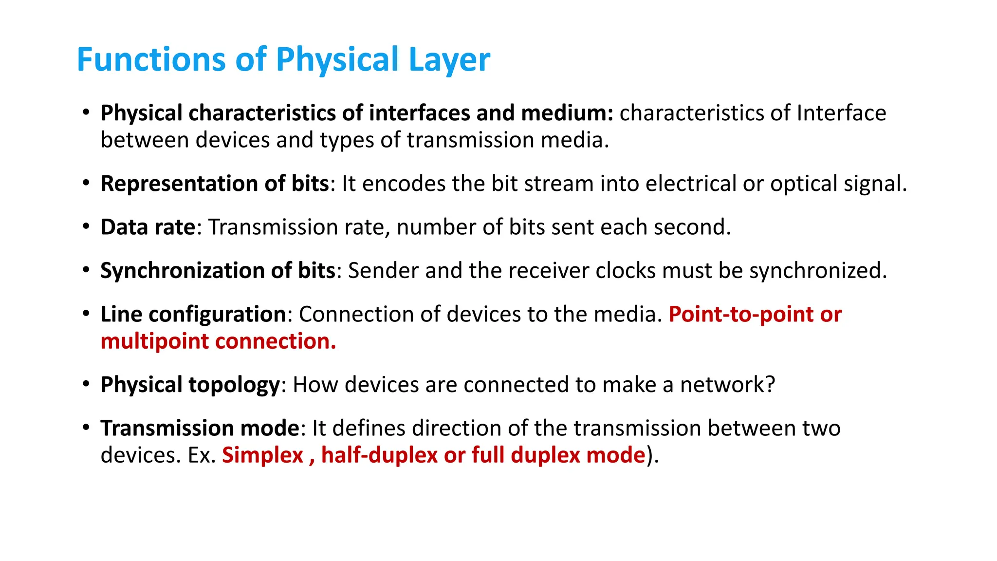
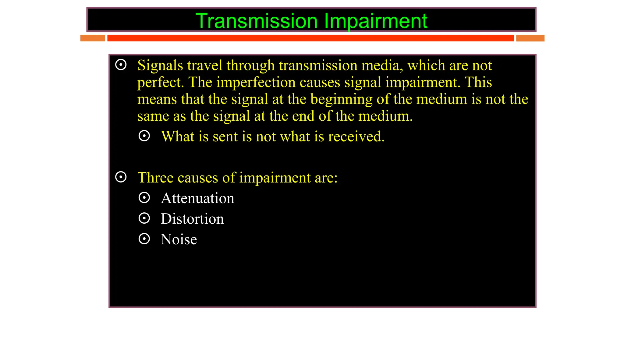
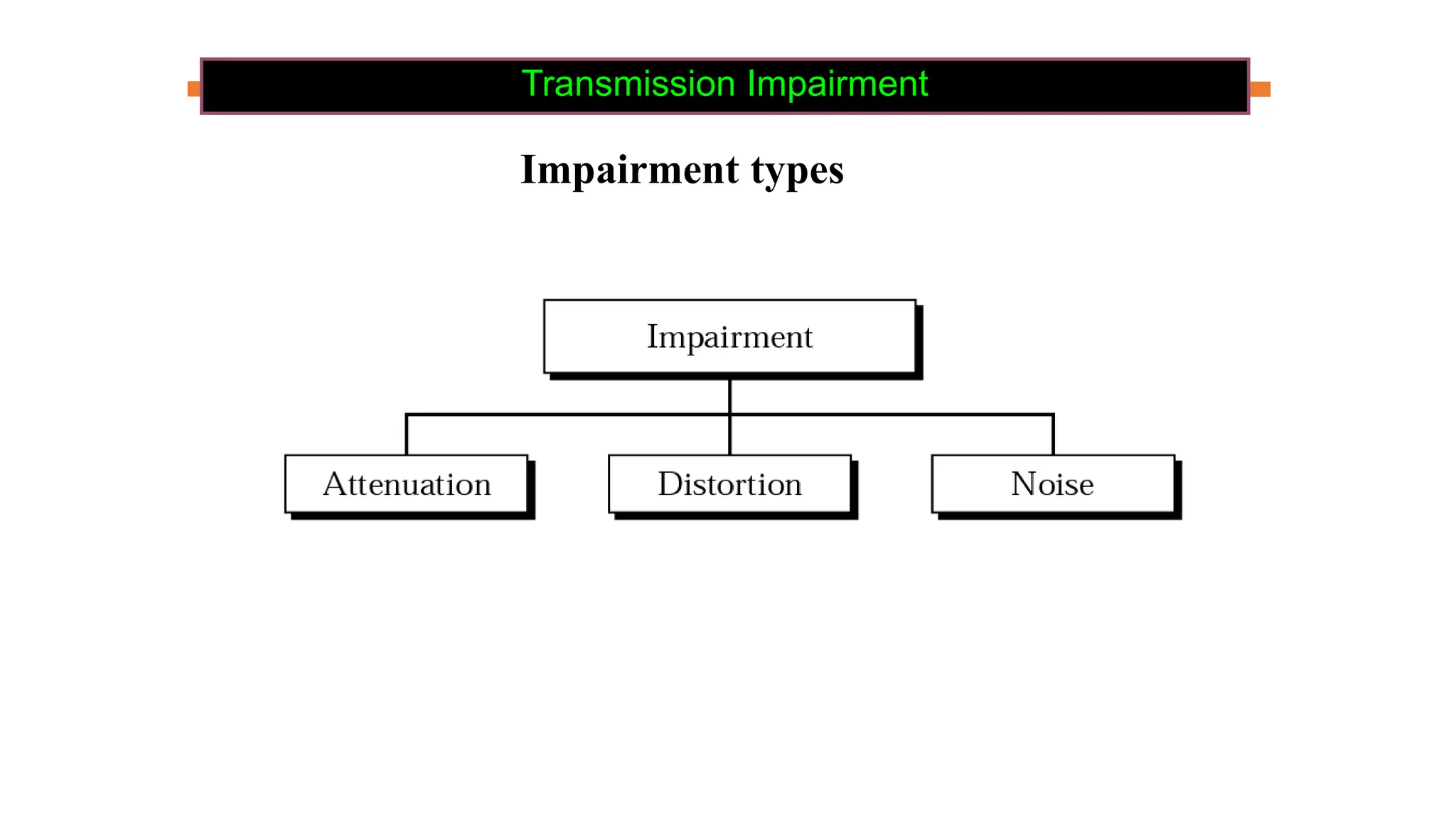
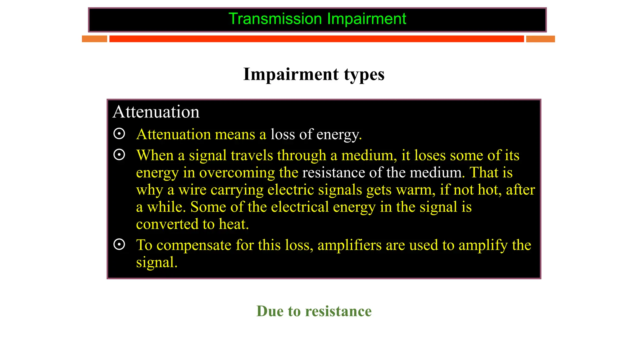
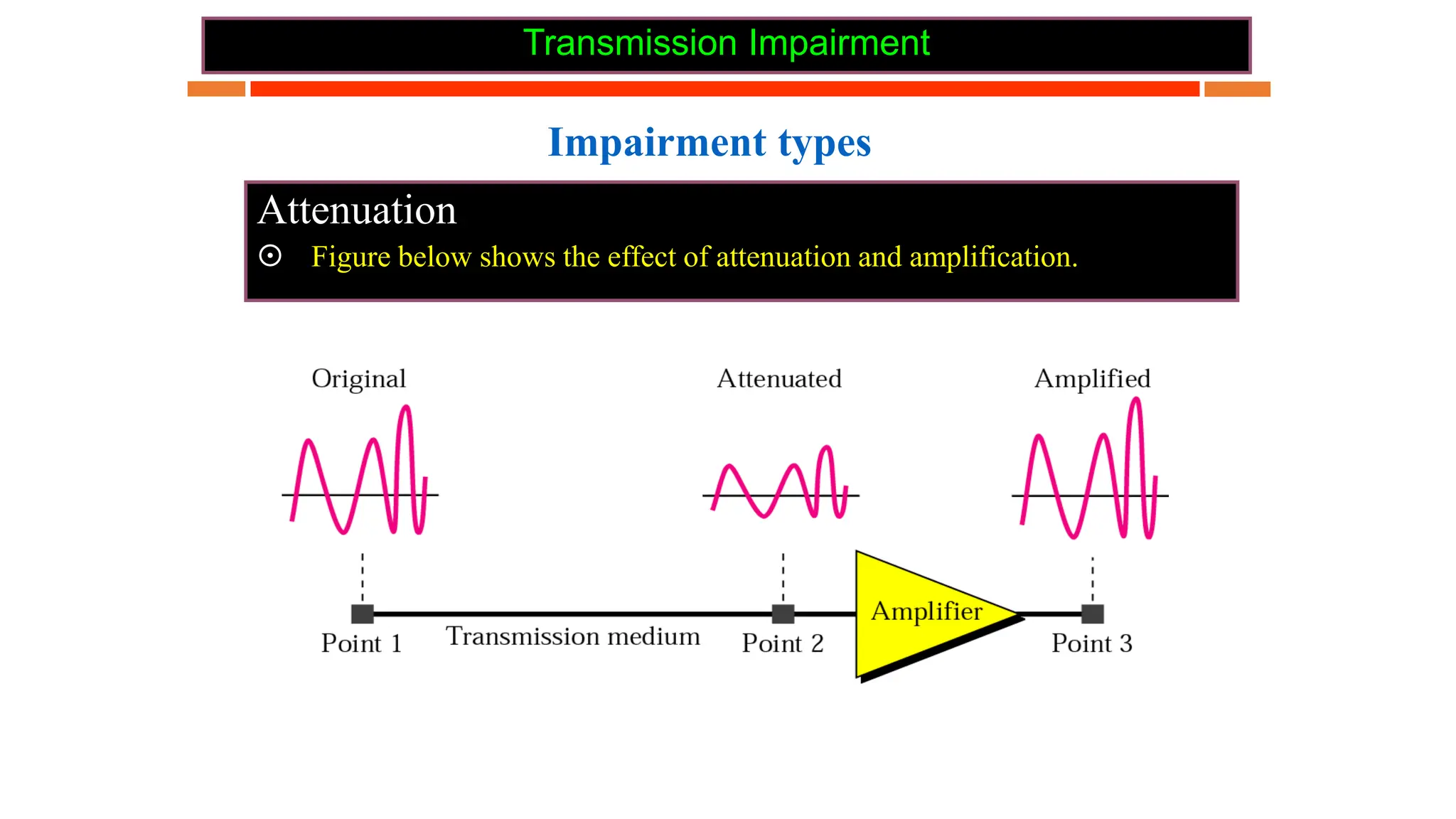
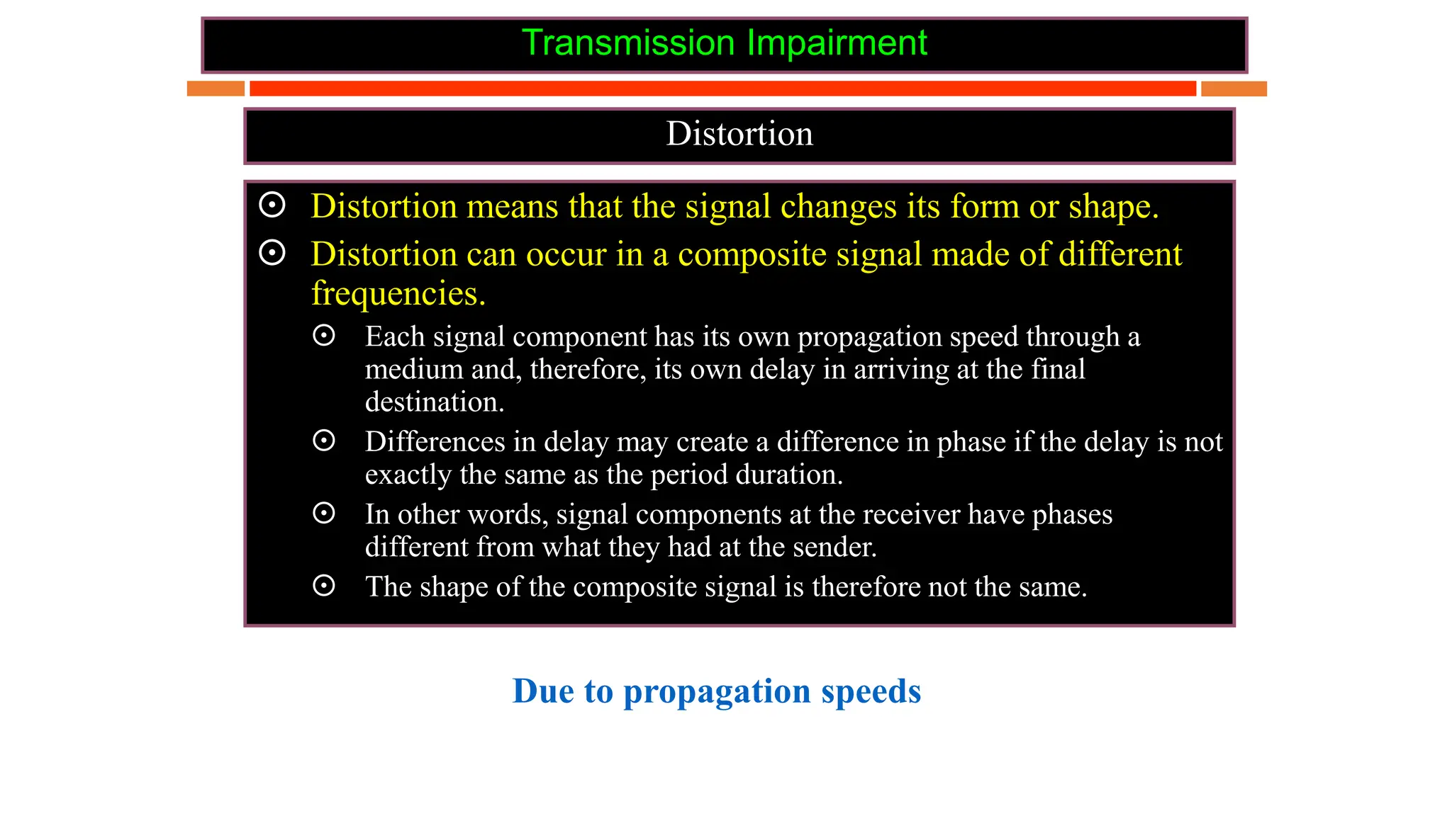
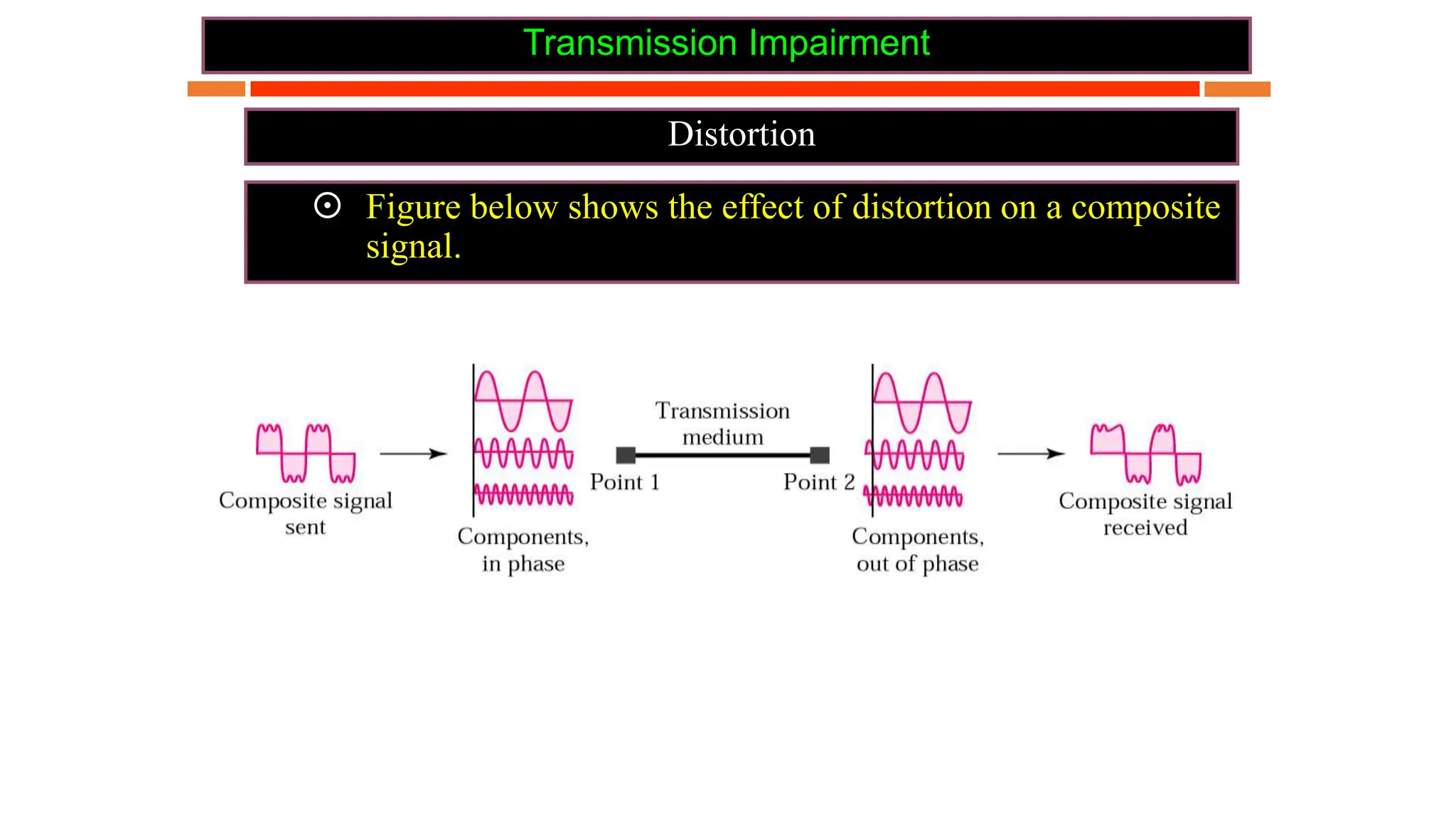
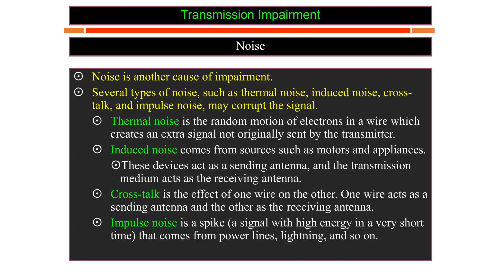
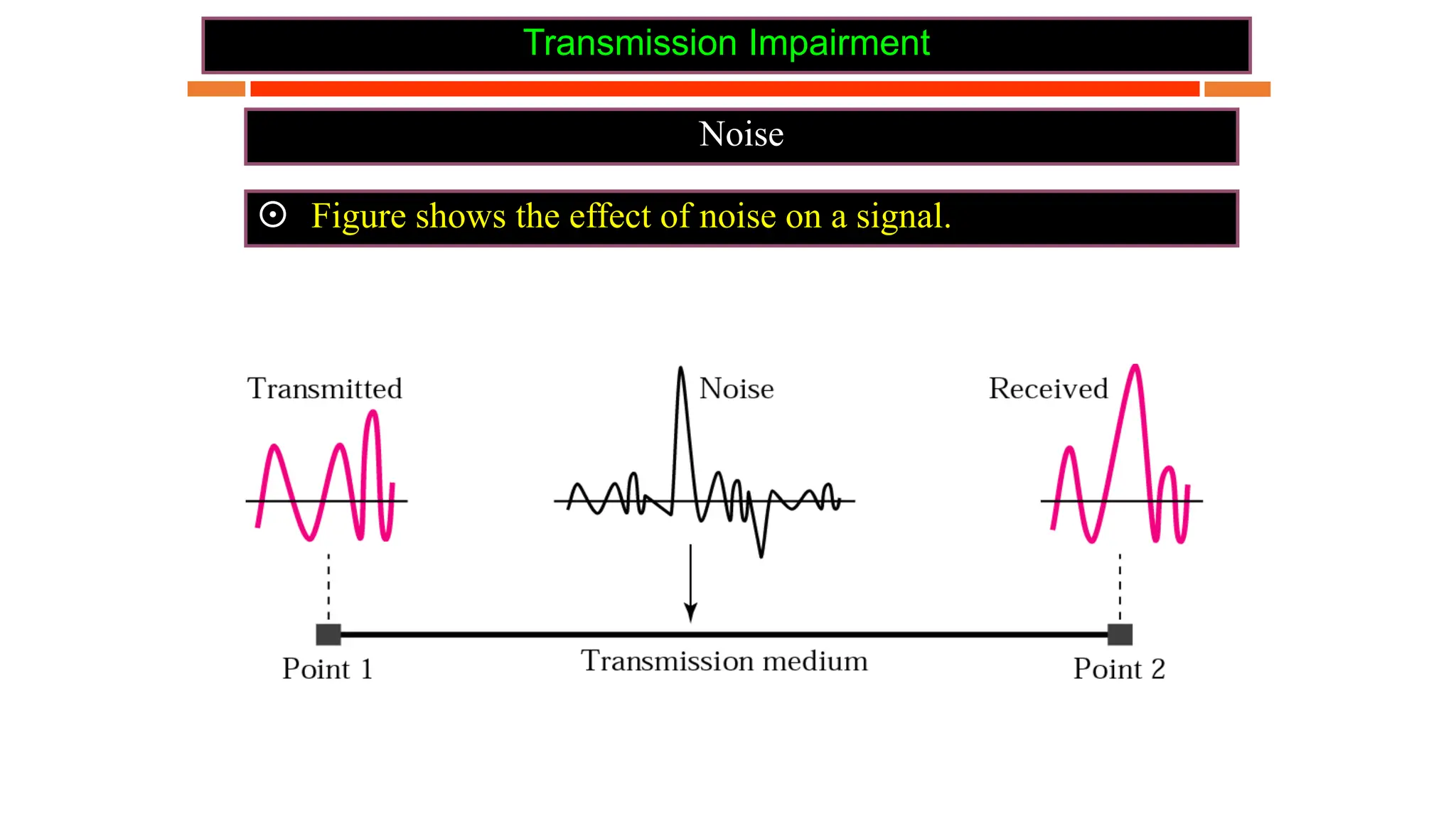
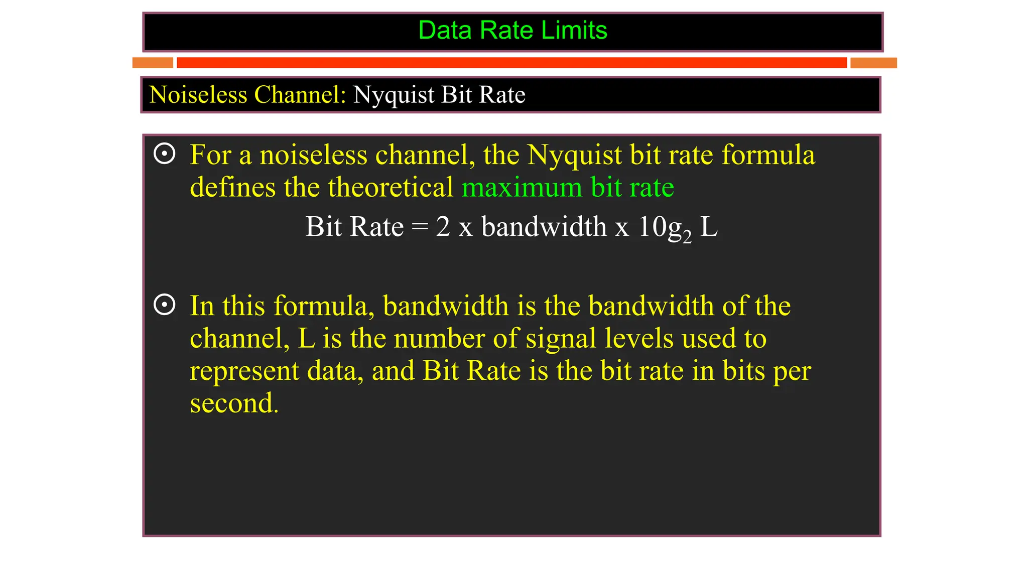
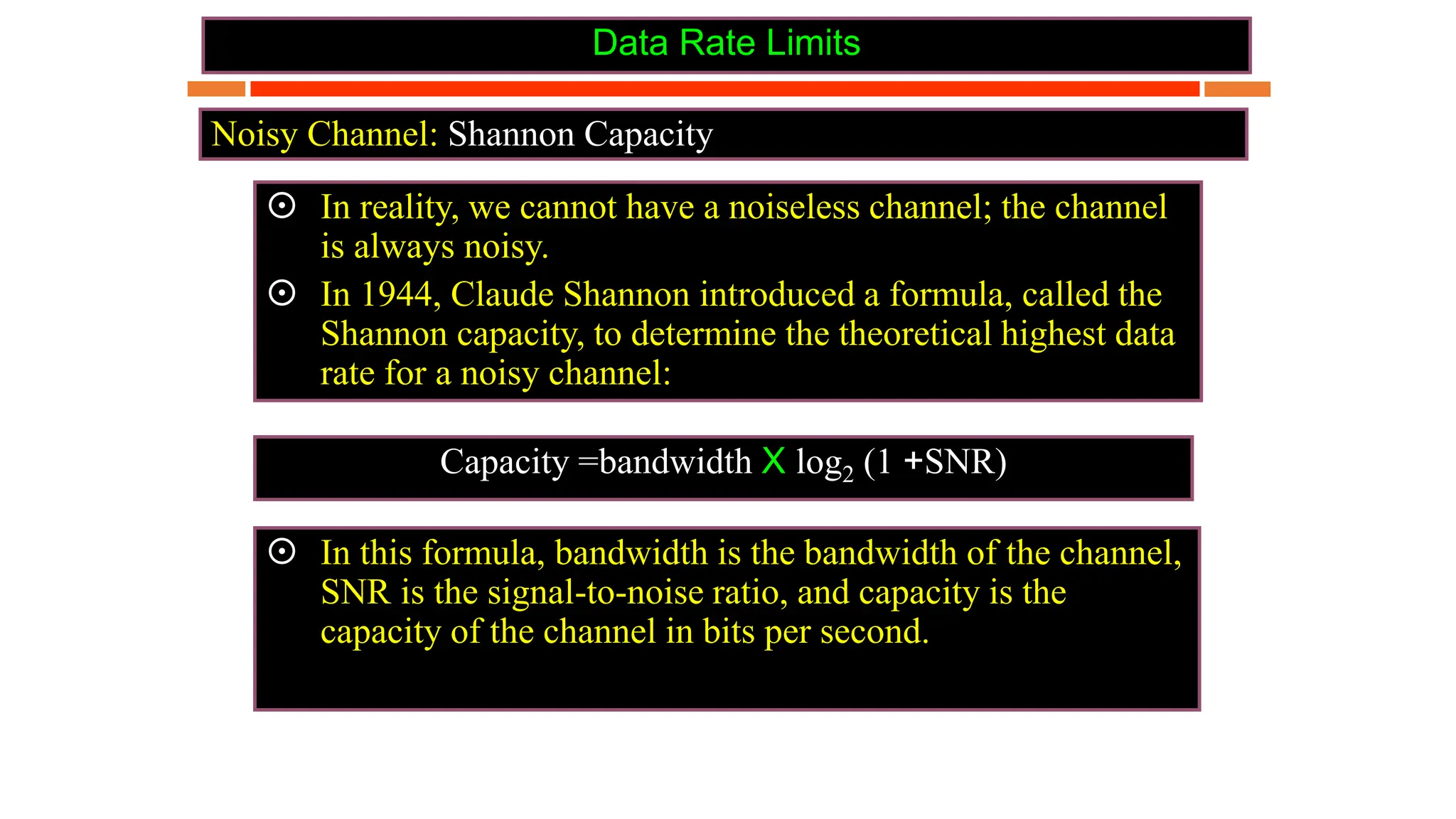
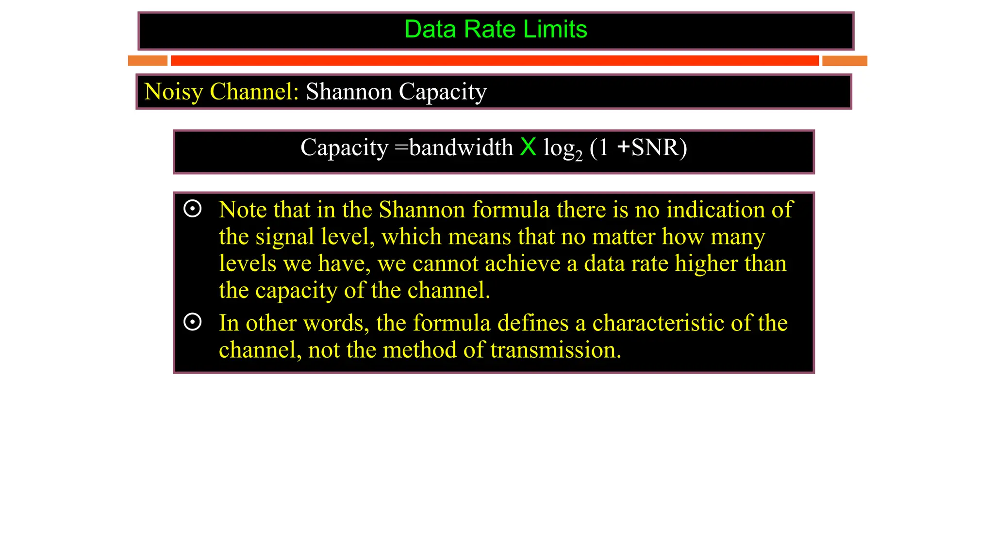
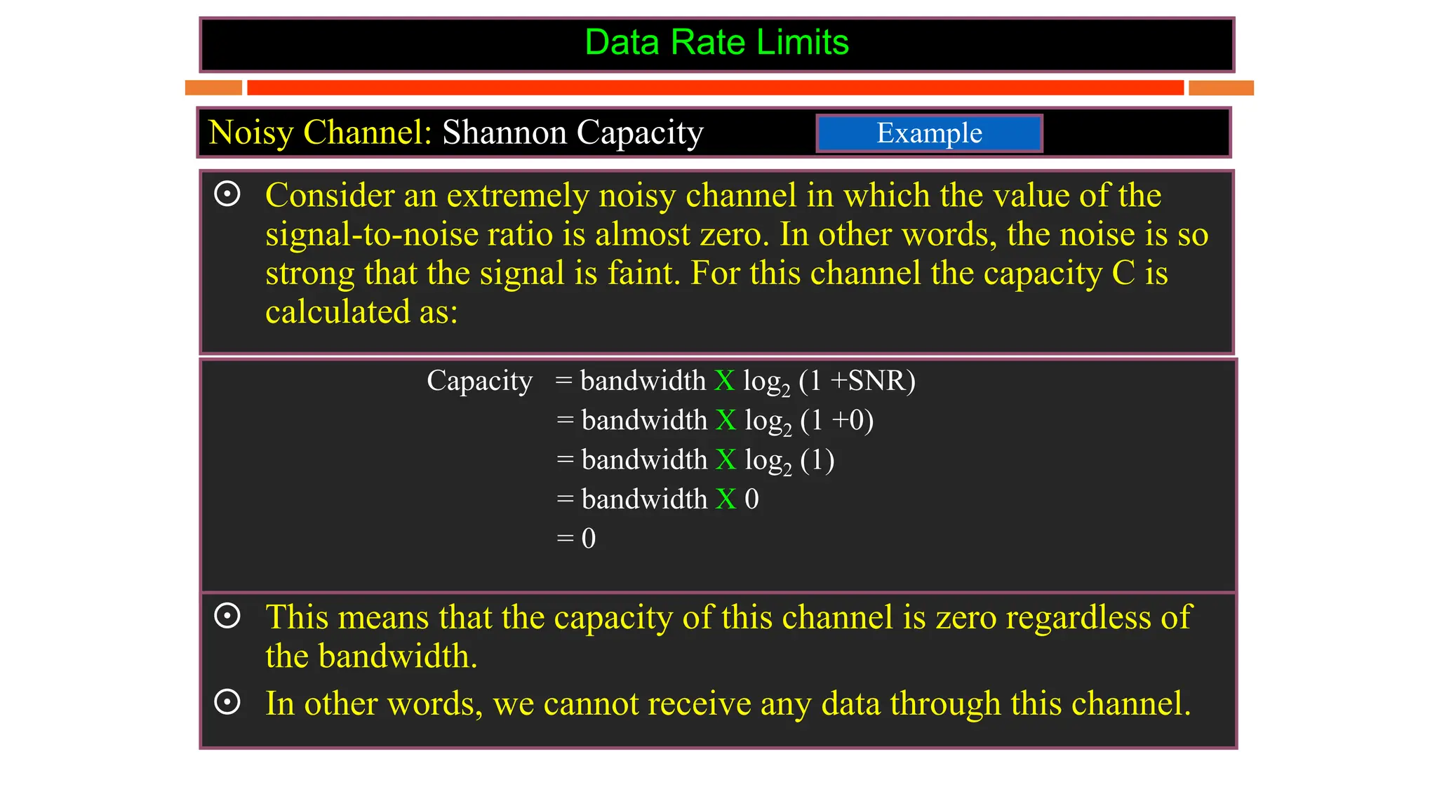
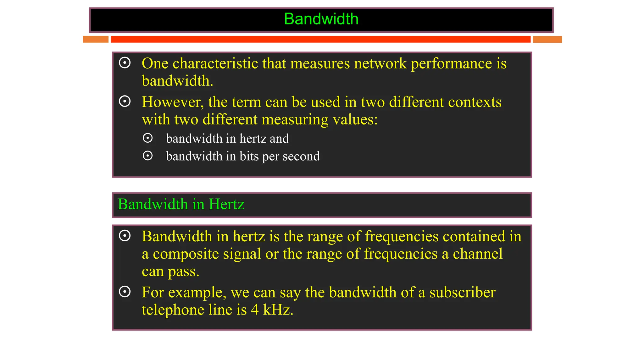
UNIT - II
Physical Layer
©Sandhya Kiran Govt Arts and Science College, Karwar
Syllabus
• Functions of Physical Layer
• Analog / Digital signals
• Transmission Impairment
• Data Rate Limits and performance
• Data Transmission Media
• Digital Modulation and Multiplexing
• Switching
Functions of Physical Layer
• Physical characteristics of interfaces and medium: characteristics of Interface
between devices and types of transmission media.
• Representation of bits: It encodes the bit stream into electrical or optical signal.
• Data rate: Transmission rate, number of bits sent each second.
• Synchronization of bits: Sender and the receiver clocks must be synchronized.
• Line configuration: Connection of devices to the media. Point-to-point or
multipoint connection.
• Physical topology: How devices are connected to make a network?
• Transmission mode: It defines direction of the transmission between two
devices. Ex. Simplex , half-duplex or full duplex mode).
Transmission Medium
In data communication,
• Transmission media is a pathway that carries the
information from sender to receiver.
• We use different types of cables or waves to transmit
data.
• Data is transmitted normally through electrical or
electromagnetic signals.
Characteristics
• A good transmission medium should provide
communication with good quality at long distance.
• For voice communication, quality of communication is
determined by the voice quality.
• For data communication, however, the quality of
communication is mainly determined by the effective
data rate of communication.
5
Factors Affecting Data Communication
of a Medium
• Communication bandwidth of the medium
• Interference
• The transmission impairments
6
• The bandwidth of a medium determines the signal
frequencies that can be carried in the medium.
• A wide bandwidth, or broadband, usually allows
communication at a higher data rate.
7
Reasons For Transmission Impairement
• Attenuation
• Distortion during signal propagation
• Noises
8
Transmission Impairment
 Signals travel through transmission media, which are not
perfect. The imperfection causes signal impairment. This
means that the signal at the beginning of the medium is not the
same as the signal at the end of the medium.
 What is sent is not what is received.
 Three causes of impairment are:
 Attenuation
 Distortion
 Noise
Transmission Impairment
Impairment types
Transmission Impairment
Impairment types
Attenuation
 Attenuation means a loss of energy.
 When a signal travels through a medium, it loses some of its
energy in overcoming the resistance of the medium. That is
why a wire carrying electric signals gets warm, if not hot, after
a while. Some of the electrical energy in the signal is
converted to heat.
 To compensate for this loss, amplifiers are used to amplify the
signal.
Due to resistance
Transmission Impairment
Impairment types
Attenuation
 Figure below shows the effect of attenuation and amplification.
Transmission Impairment
Attenuation
Decibel
 To show that a signal has lost or gained strength, we use the
unit of the decibel.
 The decibel (dB) measures the relative strengths of two
signals or one signal at two different points.
 Note that the decibel is:
 Negative if a signal is attenuated and
 Positive if a signal is amplified.
 PI and P2 are the powers of a signal at points 1 and 2, respectively.
Transmission Impairment
Attenuation
Decibel
 Note that some books define the decibel in terms of voltage
instead of power.
 In this case, because power is proportional to the square of the
voltage, the formula is:
dB = 20 log 10 (V2 / V1)
Transmission Impairment
Attenuation
Decibel
 Note that some books define the decibel in terms of voltage
instead of power.
 In this case, because power is proportional to the square of the
voltage, the formula is:
dB = 20 log 10 (V2 / V1)
Transmission Impairment
Attenuation
Example
 Suppose a signal travels through a transmission medium and
its power is reduced to one-half. This means that P2 = ½ P1.
 In this case, the attenuation (loss of power) can be calculated
as:
dB = 10 log10 (P2 / P1)
= 10 log10 (1/2 P1 / P1)
= 10 log10 (0.5))
= 10 (-0.3)
dB = -3
Other Numerical Examples from book
Transmission Impairment
Distortion
 Distortion means that the signal changes its form or shape.
 Distortion can occur in a composite signal made of different
frequencies.
 Each signal component has its own propagation speed through a
medium and, therefore, its own delay in arriving at the final
destination.
 Differences in delay may create a difference in phase if the delay is not
exactly the same as the period duration.
 In other words, signal components at the receiver have phases
different from what they had at the sender.
 The shape of the composite signal is therefore not the same.
Due to propagation speeds
Transmission Impairment
Distortion
 Figure below shows the effect of distortion on a composite
signal.
Transmission Impairment
Noise
 Noise is another cause of impairment.
 Several types of noise, such as thermal noise, induced noise, cross-
talk, and impulse noise, may corrupt the signal.
 Thermal noise is the random motion of electrons in a wire which
creates an extra signal not originally sent by the transmitter.
 Induced noise comes from sources such as motors and appliances.
These devices act as a sending antenna, and the transmission
medium acts as the receiving antenna.
 Cross-talk is the effect of one wire on the other. One wire acts as a
sending antenna and the other as the receiving antenna.
 Impulse noise is a spike (a signal with high energy in a very short
time) that comes from power lines, lightning, and so on.
Transmission Impairment
Noise
 Figure shows the effect of noise on a signal.
Transmission Impairment
Noise
 Signal-to-Noise Ratio (SNR)
 To find the theoretical bit rate limit, we need to know
the ratio of the signal power to the noise power.
 The signal-to-noise ratio is defined as:
SNR = average signal power / average noise power
 We need to consider the average signal power and the
average noise power because these may change with
time.
Transmission Impairment
Noise
 Figure shows the idea of SNR
Transmission Impairment
Noise
 Signal-to-Noise Ratio (SNR)
 SNR is actually the ratio of what is wanted (signal) to
what is not wanted (noise).
 A high SNR means the signal is less corrupted by noise;
 A low SNR means the signal is more corrupted by noise.
 Because SNR is the ratio of two powers, it is often
described in decibel units, SNRdB, defined as:
SNRdB = 10 log10 SNR
Data Rate Limits
 A very important consideration in data communications is
how fast we can send data, in bits per second. over a
channel.
 Data rate depends on three factors:
 The bandwidth available
 The level of the signals we use
 The quality of the channel (the level of noise)
 Two theoretical formulas were developed to calculate the
data rate:
 By Nyquist: For a noiseless channel
 By Shannon: For a noisy channel.
Data Rate Limits
 For a noiseless channel, the Nyquist bit rate formula
defines the theoretical maximum bit rate
Bit Rate = 2 x bandwidth x 10g2 L
 In this formula, bandwidth is the bandwidth of the
channel, L is the number of signal levels used to
represent data, and Bit Rate is the bit rate in bits per
second.
Noiseless Channel: Nyquist Bit Rate
Data Rate Limits
Bit Rate = 2 x bandwidth x 10g2 L
 According to the formula, we might think that, given a
specific bandwidth, we can have any bit rate we want by
increasing the number of signa1 leve1s.
 Although the idea is theoretically correct, practically there
is a limit. When we increase the number of signal 1eve1s,
we impose a burden on the receiver.
 If the number of levels in a signal is just 2, the receiver can
easily distinguish between a 0 and a 1.
 If the level of a signal is 64, the receiver must be very
sophisticated to distinguish between 64 different levels.
 In other words, increasing the levels of a signal reduces
the reliability of the system.
Noiseless Channel: Nyquist Bit Rate
Data Rate Limits
Example
Noiseless Channel: Nyquist Bit Rate
 Consider a noiseless channel with a bandwidth of 3000 Hz
transmitting a signal with two signal levels. What is the
maximum bit rate?
 Bit Rate =2 x 3000 x log2 2 =6000 bps
Bit Rate = 2 x bandwidth x 10g2 L
Data Rate Limits
Example
Noiseless Channel: Nyquist Bit Rate
 Consider the same noiseless channel transmitting a signal
with four signal levels (for each level, we send 2 bits).
What is the maximum bit rate?
Bit Rate =2 x 3000 x log2 4 =12, 000 bps
Bit Rate = 2 x bandwidth x 10g2 L
Data Rate Limits
Noisy Channel: Shannon Capacity
Capacity =bandwidth X log2 (1 +SNR)
 In reality, we cannot have a noiseless channel; the channel
is always noisy.
 In 1944, Claude Shannon introduced a formula, called the
Shannon capacity, to determine the theoretical highest data
rate for a noisy channel:
 In this formula, bandwidth is the bandwidth of the channel,
SNR is the signal-to-noise ratio, and capacity is the
capacity of the channel in bits per second.
Data Rate Limits
Noisy Channel: Shannon Capacity
Capacity =bandwidth X log2 (1 +SNR)
 Note that in the Shannon formula there is no indication of
the signal level, which means that no matter how many
levels we have, we cannot achieve a data rate higher than
the capacity of the channel.
 In other words, the formula defines a characteristic of the
channel, not the method of transmission.
Data Rate Limits
Noisy Channel: Shannon Capacity
Capacity = bandwidth X log2 (1 +SNR)
= bandwidth X log2 (1 +0)
= bandwidth X log2 (1)
= bandwidth X 0
= 0
 Consider an extremely noisy channel in which the value of the
signal-to-noise ratio is almost zero. In other words, the noise is so
strong that the signal is faint. For this channel the capacity C is
calculated as:
Example
 This means that the capacity of this channel is zero regardless of
the bandwidth.
 In other words, we cannot receive any data through this channel.
Bandwidth
 One characteristic that measures network performance is
bandwidth.
 However, the term can be used in two different contexts
with two different measuring values:
 bandwidth in hertz and
 bandwidth in bits per second
 Bandwidth in hertz is the range of frequencies contained in
a composite signal or the range of frequencies a channel
can pass.
 For example, we can say the bandwidth of a subscriber
telephone line is 4 kHz.
Bandwidth in Hertz
Bandwidth
 The term bandwidth can also refer to the number of bits
per second that a channel, a link, or even a network can
transmit.
 For example, one can say the bandwidth of a Fast
Ethernet network (or the links in this network) is a
maximum of 100 Mbps. This means that this network
can send 100 Mbps.
Bandwidth in Bits per Seconds
nTYPES
of
TRANSMISSION MEDIA 34
Transmission
Media
Guided
Media
Twisted
Pair
Cable
Coaxial
Cable
Fiber-Optic
Cable
Unguided
Media
Radio Microwave Satellite
35
Twisted-pair cable
 A twisted pair consists of two conductors
 Basically copper based
 With its own plastic insulation, twisted together.
36
Twisted Pair Description
• Provide protection against cross talk or interference(noise)
• One wire use to carry signals to the receiver
• Second wire used as a ground reference
• For twisting, after receiving the signal remains same.
• Therefore number of twists per unit length, determines the
quality of cable.
37
Twisted Pair
Advantages:
• Cheap
• Easy to work with
Disadvantages:
• Low data rate
• Short range
38
Twisted Pair - Applications
• Very common medium
• Can be use in telephone network
• Connection Within the buildings
• For local area networks (LAN)
39
Twisted Pair Cables
Twisted Pair cables
Unshielded
Twisted Pair
(UTP)
Shielded
Twisted pair
(STP)
40
Unshielded Twisted Pair (UTP):
Description
• Pair of unshielded wires
wound around each
other
• Easiest to install
41
Applications
UTP :
 Telephone subscribers connect to the central
telephone office
 DSL lines
 LAN – 10Mbps or 100Mbps
42
UTP Cable Types
Cat 7
Cat 6
Cat 5e
Cat 5
Cat 4
Cat 3
Cat 2
Cat 1
UTP
Cat means category according to IEEE standards.
43
Advantages of UTP:
 Affordable
 Most compatible cabling
 Major networking system
Disadvantages of UTP:
• Suffers from external Electromagnetic interference
44
Shielded Twisted Pair (STP)
• Pair of wires wound
around each other
placed inside a
protective foil wrap
• Metal braid or sheath
foil that reduces
interference
• Harder to handle (thick,
heavy)
45
STP Application
• STP is used in IBM token ring networks.
• Higher transmission rates over longer distances.
46
Advantages of STP:
 Shielded
 Faster than UTP
Disadvantages of STP:
 More expensive than UTP
 High attenuation rate
47
Co-axial cable carries signal of higher frequency ranges than twisted pair cable
Co-axial Cable
• Inner conductor is a solid wire
• Outer conductor serves as a shield against noise and a second conductor
48
Coaxial Cable Applications
• Most versatile medium
• Television distribution
• Long distance telephone transmission
• Can carry 10,000 voice calls simultaneously
• Short distance computer systems links
• Local area networks
49
ADVANTAGES
 Easy to wire
 Easy to expand
 Moderate level of Electro Magnetic Interference
DISADVANTAGE
 Single cable failure can take down an entire network
 Cost of installation of a coaxial cable is high due to its thickness and
stiffness
 Cost of maintenance is also high
COAXIAL CABLE
50
Fiber-Optic Cable
A fiber optic cable is made of glass or plastic and transmit signals in the
form of light.
Nature of light:
 Light travels in a straight line
 If light goes from one substance to another then the ray of light changes direction
 Ray of light changes direction when goes from more dense to a less dence
substance
51
Optical fiber
• Uses reflection to guide
light through a channel
• Core is of glass or plastic
surrounded by Cladding
• Cladding is of less dense
glass or plastic
An optical fiber cable has a cylindrical shape
and consists of three concentric sections:
the core, the cladding, and the jacket(outer
part of the cable).
Jacket
52
Fiber Construction
53
Fiber – Optic cable Connectors
54
Subscriber Channel (SC) Connecter
Straight-Tip (ST) Connecter
Same szie as RJ45 connector
Areas of Application
 Telecommunications
 Local Area Networks
 Cable TV
 CCTV
 Medical Education
55
Optical Fiber Advantages
 Greater capacity
Example: Data rates at 100 Gbps
 Smaller size & light weight
 Lower attenuation
 Electromagnetic isolation
 More resistance to corrosive materials
 Greater repeater spacing facility
Example: After every 10s of km at least
56
Optical Fiber Disadvantages
• Installation and maintenance need expertise
• Only Unidirectional light propagation
• Much more expensive
57
Unguided Media
Wireless transmission waves
58
 Omnidirectional Antenna
 Frequencies between 3 KHz and
1 GHz.
 Used for multicasts(multiple
way) communications, such as
radio and television, and paging
system.
 Radio waves can penetrate
buildings easily, so that widely
use for indoors & outdoors
communication.
Unguided Media – Radio Waves
59
An Antenna is a structure that is generally a metallic object may be a wire or group
of wires, used to convert high frequency current into electromagnetic waves.
Antenna are two types:
• Transmission antenna
 Transmit radio frequency from transmitter
 Radio frequency then Convert to electromagnetic energy
by antenna
 Then, radiate into surrounding environment
• Reception antenna
 Electromagnetic energy get in antenna
 Then Antenna convert radio frequency to electrical energy
 Then, Goes to receiver
same antenna can be used for both purposes
Antennas
60
Microwaves are ideal when large areas need to be covered
and there are no obstacles in the path
61
Microwaves
Micro waves Transmission
• Microwaves are unidirectional
• Micro waves electromagnetic waves having frequency
between 1 GHZ and 300 GHZ.
• There are two types of micro waves data communication
system : terrestrial and satellite
• Micro waves are widely used for one to one communication
between sender and receiver,
example: cellular phone, satellite networks and in wireless
LANs(wifi), WiMAX,GPS
62
Infrared
 Frequencies between 300 GHz to 400 THz.
 Used for short-range communication
 Example: Night Vision Camera, Remote control, File
sharing between two phones,
Communication between a PC and peripheral device,
63
Multiplexing
• Method of dividing physical channels into many logical channels so
that a number of independent signals may be simultaneously
transmitted
• Electronic device that performs multiplexing is known as a
multiplexer.
• Multiplexing enables a single transmission medium to concurrently
transmit data between several transmitters and receivers.
Multiplexing
T1 T2 T3 T4
Multiplexer
Modem
Modem
Multiplexer
computer
Types of multiplexing
• Frequency division multiplexing(FDM) is a networking technique in
which multiple data signals are combined for simultaneous
transmission via a shared communication medium.
• Time division multiplexing(TDM) is a technique used for transmitting
several message signals over a single communication channel by
dividing the time slots, one slot for message channel.
Frequency Division Multiplexing
Time Division Multiplexing
•
Network switching techniques
• Data is always transmitted from source to destination through a
network of intermediate nodes.
• Switching techniques deal with the methods of establishing
communication links between the sender and receiver in a
communication network.
• Three commonly used switching techniques are
• Circuit switching: Dedicated physical path is established between sending and
receiving stations through nodes of the network for the duration of
communication.
Network switching techniques
Message switching:
Sender appends receivers destination address to the message
and it is transmitted from source to destination either by
• Store-and-forward method and
• Broadcast method.
Message switching
D
C
5
4
2
1
B
A
Store- and - forward is a telecommunications technique in
which information is sent to an intermediate station where it is
kept and sent at a later time to the final destination or to
another intermediate station
Message Switching
• Broadcast Method– A method of sending information over a network.
• Data comes from one source and goes to all other connected sources.
• This has the side effect of congesting a medium or large network segment
very quickly.
Message
1 2 3 n
Broadcast channel
Nodes
Packet Switching
• Packet Switching refers to technologies in which messages are divided
into packets before they are sent.
• Each packet is then transmitted individually and can even follow
different routes to its destination.
• Once all the packets forming a message arrive at the destination,
they are recompiled into their original form.
• Either store-and-forward or broadcast method is used for
transmitting the packets.
Packet Switching

OSI model - physical layer,Transmission medium, switching mechanisms, multiplexing

  • 1.
    UNIT - II PhysicalLayer ©Sandhya Kiran Govt Arts and Science College, Karwar
  • 2.
    Syllabus • Functions ofPhysical Layer • Analog / Digital signals • Transmission Impairment • Data Rate Limits and performance • Data Transmission Media • Digital Modulation and Multiplexing • Switching
  • 3.
    Functions of PhysicalLayer • Physical characteristics of interfaces and medium: characteristics of Interface between devices and types of transmission media. • Representation of bits: It encodes the bit stream into electrical or optical signal. • Data rate: Transmission rate, number of bits sent each second. • Synchronization of bits: Sender and the receiver clocks must be synchronized. • Line configuration: Connection of devices to the media. Point-to-point or multipoint connection. • Physical topology: How devices are connected to make a network? • Transmission mode: It defines direction of the transmission between two devices. Ex. Simplex , half-duplex or full duplex mode).
  • 4.
    Transmission Medium In datacommunication, • Transmission media is a pathway that carries the information from sender to receiver. • We use different types of cables or waves to transmit data. • Data is transmitted normally through electrical or electromagnetic signals.
  • 5.
    Characteristics • A goodtransmission medium should provide communication with good quality at long distance. • For voice communication, quality of communication is determined by the voice quality. • For data communication, however, the quality of communication is mainly determined by the effective data rate of communication. 5
  • 6.
    Factors Affecting DataCommunication of a Medium • Communication bandwidth of the medium • Interference • The transmission impairments 6
  • 7.
    • The bandwidthof a medium determines the signal frequencies that can be carried in the medium. • A wide bandwidth, or broadband, usually allows communication at a higher data rate. 7
  • 8.
    Reasons For TransmissionImpairement • Attenuation • Distortion during signal propagation • Noises 8
  • 9.
    Transmission Impairment  Signalstravel through transmission media, which are not perfect. The imperfection causes signal impairment. This means that the signal at the beginning of the medium is not the same as the signal at the end of the medium.  What is sent is not what is received.  Three causes of impairment are:  Attenuation  Distortion  Noise
  • 10.
  • 11.
    Transmission Impairment Impairment types Attenuation Attenuation means a loss of energy.  When a signal travels through a medium, it loses some of its energy in overcoming the resistance of the medium. That is why a wire carrying electric signals gets warm, if not hot, after a while. Some of the electrical energy in the signal is converted to heat.  To compensate for this loss, amplifiers are used to amplify the signal. Due to resistance
  • 12.
    Transmission Impairment Impairment types Attenuation Figure below shows the effect of attenuation and amplification.
  • 13.
    Transmission Impairment Attenuation Decibel  Toshow that a signal has lost or gained strength, we use the unit of the decibel.  The decibel (dB) measures the relative strengths of two signals or one signal at two different points.  Note that the decibel is:  Negative if a signal is attenuated and  Positive if a signal is amplified.  PI and P2 are the powers of a signal at points 1 and 2, respectively.
  • 14.
    Transmission Impairment Attenuation Decibel  Notethat some books define the decibel in terms of voltage instead of power.  In this case, because power is proportional to the square of the voltage, the formula is: dB = 20 log 10 (V2 / V1)
  • 15.
    Transmission Impairment Attenuation Decibel  Notethat some books define the decibel in terms of voltage instead of power.  In this case, because power is proportional to the square of the voltage, the formula is: dB = 20 log 10 (V2 / V1)
  • 16.
    Transmission Impairment Attenuation Example  Supposea signal travels through a transmission medium and its power is reduced to one-half. This means that P2 = ½ P1.  In this case, the attenuation (loss of power) can be calculated as: dB = 10 log10 (P2 / P1) = 10 log10 (1/2 P1 / P1) = 10 log10 (0.5)) = 10 (-0.3) dB = -3 Other Numerical Examples from book
  • 17.
    Transmission Impairment Distortion  Distortionmeans that the signal changes its form or shape.  Distortion can occur in a composite signal made of different frequencies.  Each signal component has its own propagation speed through a medium and, therefore, its own delay in arriving at the final destination.  Differences in delay may create a difference in phase if the delay is not exactly the same as the period duration.  In other words, signal components at the receiver have phases different from what they had at the sender.  The shape of the composite signal is therefore not the same. Due to propagation speeds
  • 18.
    Transmission Impairment Distortion  Figurebelow shows the effect of distortion on a composite signal.
  • 19.
    Transmission Impairment Noise  Noiseis another cause of impairment.  Several types of noise, such as thermal noise, induced noise, cross- talk, and impulse noise, may corrupt the signal.  Thermal noise is the random motion of electrons in a wire which creates an extra signal not originally sent by the transmitter.  Induced noise comes from sources such as motors and appliances. These devices act as a sending antenna, and the transmission medium acts as the receiving antenna.  Cross-talk is the effect of one wire on the other. One wire acts as a sending antenna and the other as the receiving antenna.  Impulse noise is a spike (a signal with high energy in a very short time) that comes from power lines, lightning, and so on.
  • 20.
    Transmission Impairment Noise  Figureshows the effect of noise on a signal.
  • 21.
    Transmission Impairment Noise  Signal-to-NoiseRatio (SNR)  To find the theoretical bit rate limit, we need to know the ratio of the signal power to the noise power.  The signal-to-noise ratio is defined as: SNR = average signal power / average noise power  We need to consider the average signal power and the average noise power because these may change with time.
  • 22.
  • 23.
    Transmission Impairment Noise  Signal-to-NoiseRatio (SNR)  SNR is actually the ratio of what is wanted (signal) to what is not wanted (noise).  A high SNR means the signal is less corrupted by noise;  A low SNR means the signal is more corrupted by noise.  Because SNR is the ratio of two powers, it is often described in decibel units, SNRdB, defined as: SNRdB = 10 log10 SNR
  • 24.
    Data Rate Limits A very important consideration in data communications is how fast we can send data, in bits per second. over a channel.  Data rate depends on three factors:  The bandwidth available  The level of the signals we use  The quality of the channel (the level of noise)  Two theoretical formulas were developed to calculate the data rate:  By Nyquist: For a noiseless channel  By Shannon: For a noisy channel.
  • 25.
    Data Rate Limits For a noiseless channel, the Nyquist bit rate formula defines the theoretical maximum bit rate Bit Rate = 2 x bandwidth x 10g2 L  In this formula, bandwidth is the bandwidth of the channel, L is the number of signal levels used to represent data, and Bit Rate is the bit rate in bits per second. Noiseless Channel: Nyquist Bit Rate
  • 26.
    Data Rate Limits BitRate = 2 x bandwidth x 10g2 L  According to the formula, we might think that, given a specific bandwidth, we can have any bit rate we want by increasing the number of signa1 leve1s.  Although the idea is theoretically correct, practically there is a limit. When we increase the number of signal 1eve1s, we impose a burden on the receiver.  If the number of levels in a signal is just 2, the receiver can easily distinguish between a 0 and a 1.  If the level of a signal is 64, the receiver must be very sophisticated to distinguish between 64 different levels.  In other words, increasing the levels of a signal reduces the reliability of the system. Noiseless Channel: Nyquist Bit Rate
  • 27.
    Data Rate Limits Example NoiselessChannel: Nyquist Bit Rate  Consider a noiseless channel with a bandwidth of 3000 Hz transmitting a signal with two signal levels. What is the maximum bit rate?  Bit Rate =2 x 3000 x log2 2 =6000 bps Bit Rate = 2 x bandwidth x 10g2 L
  • 28.
    Data Rate Limits Example NoiselessChannel: Nyquist Bit Rate  Consider the same noiseless channel transmitting a signal with four signal levels (for each level, we send 2 bits). What is the maximum bit rate? Bit Rate =2 x 3000 x log2 4 =12, 000 bps Bit Rate = 2 x bandwidth x 10g2 L
  • 29.
    Data Rate Limits NoisyChannel: Shannon Capacity Capacity =bandwidth X log2 (1 +SNR)  In reality, we cannot have a noiseless channel; the channel is always noisy.  In 1944, Claude Shannon introduced a formula, called the Shannon capacity, to determine the theoretical highest data rate for a noisy channel:  In this formula, bandwidth is the bandwidth of the channel, SNR is the signal-to-noise ratio, and capacity is the capacity of the channel in bits per second.
  • 30.
    Data Rate Limits NoisyChannel: Shannon Capacity Capacity =bandwidth X log2 (1 +SNR)  Note that in the Shannon formula there is no indication of the signal level, which means that no matter how many levels we have, we cannot achieve a data rate higher than the capacity of the channel.  In other words, the formula defines a characteristic of the channel, not the method of transmission.
  • 31.
    Data Rate Limits NoisyChannel: Shannon Capacity Capacity = bandwidth X log2 (1 +SNR) = bandwidth X log2 (1 +0) = bandwidth X log2 (1) = bandwidth X 0 = 0  Consider an extremely noisy channel in which the value of the signal-to-noise ratio is almost zero. In other words, the noise is so strong that the signal is faint. For this channel the capacity C is calculated as: Example  This means that the capacity of this channel is zero regardless of the bandwidth.  In other words, we cannot receive any data through this channel.
  • 32.
    Bandwidth  One characteristicthat measures network performance is bandwidth.  However, the term can be used in two different contexts with two different measuring values:  bandwidth in hertz and  bandwidth in bits per second  Bandwidth in hertz is the range of frequencies contained in a composite signal or the range of frequencies a channel can pass.  For example, we can say the bandwidth of a subscriber telephone line is 4 kHz. Bandwidth in Hertz
  • 33.
    Bandwidth  The termbandwidth can also refer to the number of bits per second that a channel, a link, or even a network can transmit.  For example, one can say the bandwidth of a Fast Ethernet network (or the links in this network) is a maximum of 100 Mbps. This means that this network can send 100 Mbps. Bandwidth in Bits per Seconds
  • 34.
  • 35.
  • 36.
    Twisted-pair cable  Atwisted pair consists of two conductors  Basically copper based  With its own plastic insulation, twisted together. 36
  • 37.
    Twisted Pair Description •Provide protection against cross talk or interference(noise) • One wire use to carry signals to the receiver • Second wire used as a ground reference • For twisting, after receiving the signal remains same. • Therefore number of twists per unit length, determines the quality of cable. 37
  • 38.
    Twisted Pair Advantages: • Cheap •Easy to work with Disadvantages: • Low data rate • Short range 38
  • 39.
    Twisted Pair -Applications • Very common medium • Can be use in telephone network • Connection Within the buildings • For local area networks (LAN) 39
  • 40.
    Twisted Pair Cables TwistedPair cables Unshielded Twisted Pair (UTP) Shielded Twisted pair (STP) 40
  • 41.
    Unshielded Twisted Pair(UTP): Description • Pair of unshielded wires wound around each other • Easiest to install 41
  • 42.
    Applications UTP :  Telephonesubscribers connect to the central telephone office  DSL lines  LAN – 10Mbps or 100Mbps 42
  • 43.
    UTP Cable Types Cat7 Cat 6 Cat 5e Cat 5 Cat 4 Cat 3 Cat 2 Cat 1 UTP Cat means category according to IEEE standards. 43
  • 44.
    Advantages of UTP: Affordable  Most compatible cabling  Major networking system Disadvantages of UTP: • Suffers from external Electromagnetic interference 44
  • 45.
    Shielded Twisted Pair(STP) • Pair of wires wound around each other placed inside a protective foil wrap • Metal braid or sheath foil that reduces interference • Harder to handle (thick, heavy) 45
  • 46.
    STP Application • STPis used in IBM token ring networks. • Higher transmission rates over longer distances. 46
  • 47.
    Advantages of STP: Shielded  Faster than UTP Disadvantages of STP:  More expensive than UTP  High attenuation rate 47
  • 48.
    Co-axial cable carriessignal of higher frequency ranges than twisted pair cable Co-axial Cable • Inner conductor is a solid wire • Outer conductor serves as a shield against noise and a second conductor 48
  • 49.
    Coaxial Cable Applications •Most versatile medium • Television distribution • Long distance telephone transmission • Can carry 10,000 voice calls simultaneously • Short distance computer systems links • Local area networks 49
  • 50.
    ADVANTAGES  Easy towire  Easy to expand  Moderate level of Electro Magnetic Interference DISADVANTAGE  Single cable failure can take down an entire network  Cost of installation of a coaxial cable is high due to its thickness and stiffness  Cost of maintenance is also high COAXIAL CABLE 50
  • 51.
    Fiber-Optic Cable A fiberoptic cable is made of glass or plastic and transmit signals in the form of light. Nature of light:  Light travels in a straight line  If light goes from one substance to another then the ray of light changes direction  Ray of light changes direction when goes from more dense to a less dence substance 51
  • 52.
    Optical fiber • Usesreflection to guide light through a channel • Core is of glass or plastic surrounded by Cladding • Cladding is of less dense glass or plastic An optical fiber cable has a cylindrical shape and consists of three concentric sections: the core, the cladding, and the jacket(outer part of the cable). Jacket 52
  • 53.
  • 54.
    Fiber – Opticcable Connectors 54 Subscriber Channel (SC) Connecter Straight-Tip (ST) Connecter Same szie as RJ45 connector
  • 55.
    Areas of Application Telecommunications  Local Area Networks  Cable TV  CCTV  Medical Education 55
  • 56.
    Optical Fiber Advantages Greater capacity Example: Data rates at 100 Gbps  Smaller size & light weight  Lower attenuation  Electromagnetic isolation  More resistance to corrosive materials  Greater repeater spacing facility Example: After every 10s of km at least 56
  • 57.
    Optical Fiber Disadvantages •Installation and maintenance need expertise • Only Unidirectional light propagation • Much more expensive 57
  • 58.
  • 59.
     Omnidirectional Antenna Frequencies between 3 KHz and 1 GHz.  Used for multicasts(multiple way) communications, such as radio and television, and paging system.  Radio waves can penetrate buildings easily, so that widely use for indoors & outdoors communication. Unguided Media – Radio Waves 59
  • 60.
    An Antenna isa structure that is generally a metallic object may be a wire or group of wires, used to convert high frequency current into electromagnetic waves. Antenna are two types: • Transmission antenna  Transmit radio frequency from transmitter  Radio frequency then Convert to electromagnetic energy by antenna  Then, radiate into surrounding environment • Reception antenna  Electromagnetic energy get in antenna  Then Antenna convert radio frequency to electrical energy  Then, Goes to receiver same antenna can be used for both purposes Antennas 60
  • 61.
    Microwaves are idealwhen large areas need to be covered and there are no obstacles in the path 61 Microwaves
  • 62.
    Micro waves Transmission •Microwaves are unidirectional • Micro waves electromagnetic waves having frequency between 1 GHZ and 300 GHZ. • There are two types of micro waves data communication system : terrestrial and satellite • Micro waves are widely used for one to one communication between sender and receiver, example: cellular phone, satellite networks and in wireless LANs(wifi), WiMAX,GPS 62
  • 63.
    Infrared  Frequencies between300 GHz to 400 THz.  Used for short-range communication  Example: Night Vision Camera, Remote control, File sharing between two phones, Communication between a PC and peripheral device, 63
  • 65.
    Multiplexing • Method ofdividing physical channels into many logical channels so that a number of independent signals may be simultaneously transmitted • Electronic device that performs multiplexing is known as a multiplexer. • Multiplexing enables a single transmission medium to concurrently transmit data between several transmitters and receivers.
  • 66.
    Multiplexing T1 T2 T3T4 Multiplexer Modem Modem Multiplexer computer
  • 67.
    Types of multiplexing •Frequency division multiplexing(FDM) is a networking technique in which multiple data signals are combined for simultaneous transmission via a shared communication medium. • Time division multiplexing(TDM) is a technique used for transmitting several message signals over a single communication channel by dividing the time slots, one slot for message channel.
  • 68.
  • 69.
  • 70.
    Network switching techniques •Data is always transmitted from source to destination through a network of intermediate nodes. • Switching techniques deal with the methods of establishing communication links between the sender and receiver in a communication network. • Three commonly used switching techniques are • Circuit switching: Dedicated physical path is established between sending and receiving stations through nodes of the network for the duration of communication.
  • 71.
    Network switching techniques Messageswitching: Sender appends receivers destination address to the message and it is transmitted from source to destination either by • Store-and-forward method and • Broadcast method.
  • 72.
    Message switching D C 5 4 2 1 B A Store- and- forward is a telecommunications technique in which information is sent to an intermediate station where it is kept and sent at a later time to the final destination or to another intermediate station
  • 73.
    Message Switching • BroadcastMethod– A method of sending information over a network. • Data comes from one source and goes to all other connected sources. • This has the side effect of congesting a medium or large network segment very quickly. Message 1 2 3 n Broadcast channel Nodes
  • 74.
    Packet Switching • PacketSwitching refers to technologies in which messages are divided into packets before they are sent. • Each packet is then transmitted individually and can even follow different routes to its destination. • Once all the packets forming a message arrive at the destination, they are recompiled into their original form. • Either store-and-forward or broadcast method is used for transmitting the packets.
  • 75.