Optimised and balanced structural of offshore wind turbines
1. Risø-R-1420(EN)
Optimised and Balanced
Structural and System Reliability
of Offshore Wind Turbines
An account
Niels Jacob Tarp-Johansen, Risø National Laboratory
Igor Kozine, Risø National Laboratory
Luc Rademarkers, Netherlands Energy Research Foundation
John Dalsgaard Sørensen, Aalborg University
Knut Ronold, Det Norske Veritas
Risø National Laboratory, Roskilde
April 2005
2. Abstract
This report gives the results of the research project “Optimised and Uniform
Safety and Reliability of Offshore Wind Turbines (an account)”. The main sub-
ject of the project has been the account of the state-of-the art of knowledge
about, and/or attempts to, harmonisation of the structural reliability of wind tur-
bines, on the one hand, and the reliability of the wind turbine’s control/safety
system, on the other hand. Within the project some research pointing ahead has
also been conducted.
ISBN 87-550-3240-0; 87-550-3241-9 (Internet)
ISSN 0106-2840
Print: Danka Services International A/S, 2005
3. Contents
Preface 5
Introduction 7
1 State-of-the-Art 9
1.1 Safety Philosophy of Wind Turbines System Reliability 9
1.2 Structural Reliability 11
1.2.1 Blade Design 12
1.2.2 Support Structure 13
1.3 Risk Analysis 14
2 Framework 15
2.1 General Framework 15
2.2 Refined and Feasible Framework 17
2.3 Compatibility of the Methods of System Reliability and Structural
Reliability 20
3 System Reliability 23
3.1 Factors that influence the system reliability 23
3.2 Analysis of major wind turbine failures taking place in 1984-2000 in
Denmark 26
3.2.1 Introduction to the analysis 26
3.2.2 Failure Data Analysis 27
3.2.3 Detailed conclusions drawn from the failure data analysis 27
3.3 Forecasting system reliabilities 30
3.4 Gaining more insight from the data analysis and developed approach 31
4 Structural Reliability 35
4.1 Structural Reliability – Aerodynamic Loads 35
4.1.1 Typical Reliability Levels 37
4.1.2 IEC Reliability levels 38
4.2 Structural Reliability – Hydrodynamic Loads 39
4.3 Cost-Optimal Structural Reliability of Offshore turbines 44
4.3.1 An example 45
4.4 Comparing the Results of Structural Reliability and System Reliability
Assessments 49
5 Conclusions 50
5.1 Project contents 50
5.2 Main conclusions 50
5.3 Some detailed conclusions 51
5.4 Recommendation for future research 52
References 54
Appendix A: Failure data and their classification 56
Appendix B: Model Uncertainties for Wave Loads on Wind Turbine
Foundations 78
3 Risø-R-1420(EN)
5. Preface
This report constitutes the main report of the project “Optimised and Uniform
Safety and Reliability of Offshore Wind Turbines (an account)” under the Dan-
ish Public Service Obligation (PSO) research programme financed by the Dan-
ish power supply companies ELKRAFT system and ELSAM. This project has
been supported by ELKRAFT system under contract no. BRO-91.058 (PSO no.
FU1101).
Other reports, which support the conclusions drawn herein, have been prepared
during the course of the project. These are
• Background document for Partial Safety Factors for Extreme Load Ef-
fects, Proposal for the 3rd Ed. of IEC 61400: Wind Turbine Generator
Systems - Part 1: Safety Requirements
• Examples of application of Bayesian probabilistic networks
• Reliability-based optimization of wind turbines
Out of these reports the first report has, in approximately equal shares, been co-
supported by another PSO-project, namely “Offshoremøller, kombinerede las-
ter” (contract no. BRO-91.007, PSO no. FU0013 (ELKRAFT system)), and by
the EU project “Recommendations For Design Of Offshore Wind Turbines”
project no. ENK5-CT-2000-00322.
5 Risø-R-1420(EN)
7. Introduction
The reliability of wind turbines against wind loads does not depend on the
strength of the load carrying components of the turbine structure and the wind
climate alone. A wind turbine is equipped with a control/safety system that,
among many other things, is supposed to bring the turbine into a load-reducing
mode if the wind speed rises above some predefined level, typically known as
the cut-out wind speed. The control/safety system is also supposed to bring the
turbine to calm in case of accidental events like over-speed. Thus the reliability
of a turbine against wind loads clearly depends also on the reliability of the con-
trol/safety system.
In current design practise the implicit basic assumption is that the control/safety
system should never fail, which is ensured through redundancy. If this holds
true in reality the reliability of wind turbines against wind loads will of course
not depend on the control/safety system. (That is, the reliability will not depend
on the control/safety system to the extent that it has been designed to cover all
possible events that would reasonably require its activation, but this has nothing
to do with its reliability.)
There is no reason to believe that control/safety systems, even if they are prop-
erly maintained, will never fail in practise. This is completely analogous to the
fact that one expects the structure of wind turbines to collapse now and then. If
a certain level of reliability of wind turbines against wind loads is wanted a suit-
able balance between the structural reliability and the system reliability must
therefore be found.
In the preceding paragraph, and in the remainder of this report, structural reli-
ability is used as abbreviation for “the reliability of the wind turbine structure”
and system reliability is an abbreviation for “the reliability of the control/safety
system”. The authors realise this is not necessarily the same meaning of the
terms as is usually used in the specific field of structural reliability methods and
in the general field of reliability analysis. The abbreviations are however used
for the sake of brevity and readability.
In the present report there is made no distinction between the control system
and the safety system. This distinction is avoided because long discussions that
are not directly relevant to the conclusions of this report can arise. For instance
some may argue that the shut down at the cut-out wind speed is a feature of the
control system, whereas others may consider it an intervention of the safety sys-
tem because it is a prevention against wind loads that may compromise the reli-
ability of the turbine. In any case the bottom line is that the same computer gov-
erns both the control and the safety systems, which implies that an error in the
computer may affect both systems. So, independent of how one distinguishes
between the control and the safety system the outcome is the same, namely: the
reliability of the mechanisms of the control/safety system affects the over-all
reliability of the turbine against wind loads.
The project was motivated by the suspicion that there is an unfavourable unbal-
ance between the structural reliability and the system reliability of wind tur-
bines. To get an account of this subject with focus on offshore turbines has been
7 Risø-R-1420(EN)
8. the prime aim of the project. In the project it has been documented that for older
onshore turbines such an unfavourable unbalance exists. The question is if this
is true for newer turbines onshore or offshore as well. It is expected to be much
less pronounced, however this has been hard to document, as one of the main
obstacles of research in this field has turned out to be the access to both recent
and unambiguous failure data for turbine structures or structural components
and/or reliable failure data for sub-systems of the control/safety system. Exam-
ining structural failure data the unbalance manifests itself as relatively more
structural failures initiated by malfunctioning of the control/safety system than
by extreme wind loads exceeding the design loads or by material strengths be-
low the design strength. Because the control/safety system is considerably
cheaper than the turbine structure this unbalance seems unfavourable. One
would expect the opposite to be cost-optimal. From the observation of the un-
balance the following question emerges:
• Is the unbalance notable?
• Is the over-all reliability (i.e. the combined structural and system reli-
ability) acceptable anyways?
• If yes to both the above questions, then perhaps the structural reliability
may be reduced and the system reliability slightly increased?
• If a higher level of over-all reliability is wanted, would it suffice to in-
crease the system reliability?
• Could an even lower level of over-all reliability be accepted?
Bearing these questions in mind, but also realising that they are hard to answer
within the current project, the project partners have been looking into the possi-
bilities of aiming at possibly lower, i.e. optimised, structural reliability levels
for future offshore turbines and of ways to ensure proper balance between struc-
tural reliability and system reliability in future wind turbines. The proper bal-
ance is not necessarily obtained by uniform reliabilities as implied by the pro-
ject title. The project has therefore contained the following tasks
• An account of the state-of-the-art within the areas of structural reliability
analysis and system reliability analysis in wind turbine engineering,
• Data analysis on empirical failure data reported for existing wind tur-
bines,
• Theoretical assessment of the structural reliability
• Theoretical assessment of cost-optimal structural reliability
Though present days data in general cannot support a reliable outcome of the
tasks listed the formulation of methodologies for the calibration of structural
reliability (which typically leads to assessment of partial safety factors) includ-
ing the system reliability is also regarded in the present report. Two cases are
considered: 1) the system reliability has a fixed value and the structural reliabil-
ity is adjusted so that a given over-all target reliability is reached, and 2) the
system reliability and the structural reliability levels are two out of more vari-
ables in an optimisation problem leading to cost-optimal over-all reliability.
The structure of the report reflects the above task list and its ordering.
8 Risø-R-1420(EN)
9. 1 State-of-the-Art
As a first step in the project, it is necessary to make a historical overview of
work that has been carried out up to now and to summarise the main conclu-
sions in order to determine the white gaps and future R&D needs.
Since the beginning of the nineties, ECN, Risø and others have been carrying
out projects that aimed at implementing probabilistic design and analysis tech-
niques in wind turbine engineering. A list of projects is given in Appendix C,
and references [1] through [15] gives a list of documents concerning the subject.
1.1 Safety Philosophy of Wind Turbines System
Reliability
In case probabilistic design techniques are being used, safety is defined as:
Safety: the probability that a system will perform satisfactorily and without
occurrence of accidents, when used under stated conditions.
In case of wind turbines this could be interpreted as the probability that a wind
turbine will fail and loose structural parts. Worthwhile mentioning in the gen-
eral definition of safety is the phrase “under stated conditions”. In case of wind
turbines, the stated conditions are to be considered as the external conditions to
which the turbine is designed for. The “stated conditions” correspond to a large
extent to the load situations as defined for instance in the national or interna-
tional safety standards (e.g. IEC 61400-1). “Stated conditions” are for instance
maximum wind speed, maximum turbulence levels, annual frequency of grid
loss, etc.
When applying the general safety definition to wind turbines, there is a prob-
ability that a wind turbine can fail in four situations.
1. if the turbine operates within its operational limits, and the external condi-
tions are within the design values;
2. if the turbine operates outside its operational limits (e.g. overspeed), and the
external conditions are within the design values;
3. if the turbine operates within its operational limits, and the external condi-
tions are more severe than the design conditions (e.g. wind speeds above 1
per 50 year storms);
4. if the turbine operates outside its operational limits (e.g. overspeed), and the
external conditions are more severe than the design conditions (e.g. wind
speeds above 1 per 50 year storms).
Situation 1: If the turbine fails as long as it is within its operational limits and
the external conditions are within the design values, it is very likely that the
failure mechanism is a structural failure, e.g.:
• insufficient strength due to corrosion, “optimistic” design procedures and
underestimation of loads, unforeseen degradation of material, poor manu-
facturing process;
• insufficient pre-tensioning of bolts (bad maintenance?).
9 Risø-R-1420(EN)
10. Structural reliability analyses (not only very advanced methods but also the use
of partial safety factors), seems the best method to deal with such failures.
FMECA’s (Failure Mode and Effects and Consequences Analysis, i.e. system
reliability) may assist in identifying weak spots in the design and maintenance
procedures.
Situation 2: If the turbine fails if it is outside its operational limits and the ex-
ternal conditions are within the design values, it is very likely that the failure
mechanism has to do with failure of the safety system. Normally, the safety sys-
tems should prevent the turbine from exceeding its operational limits (over-
speed, yaw-misalignment, etc.). Traditionally, and in accordance, with most
safety standards (IEC 61400-1, NEN 11400, Danish Codes, GL criteria, ???) a
turbine should be equipped with two safety systems that operate independently
and are activated diversely. In fact, the safety codes do not give target values for
the probability of failure of both safety systems.
A detailed qualitative reliability analysis of the safety and control systems could
reveal which failure modes are to be considered as “within the operational lim-
its” or as “outside the operational limits”. In accordance with safety codes, most
single failures are to be considered as normal design situations. As soon as the
single failures and the resulting load situations have been identified, one can
decide on how to proceed. (1) Further evaluating the load situation and assess
the structural integrity (structural reliability) or (2) modifying the design (re-
dundancy) and reducing the occurrence frequency of the load situation (system
reliability).
Example: A turbine is equipped with two safety systems.
During the start-up procedure, the turbine is not grid con-
nected. The controller makes use of the rotor speed signal. If
the speed sensor fails, it generates “zero speed” and the con-
troller allows the rotor to speed up until overspeed is detected
by the second overspeed sensor. The turbine will stop by
means of an emergency shut down. This situation only reveals
from a detailed system analysis. If the reliability of the speed
sensing system is high, one can decide to analyse this load
situation (structural reliability) as an “ultimate load situation”.
If it is expected that the situation will occur frequently, and
will lead to unacceptably high fatigue loads, one can decide to
improve the reliability of the speed sensing system (system re-
liability).
Experiences up to now have learned that situations as given in the example,
only reveal if a detailed systems analysis is performed. An event tree analysis is
very helpful. Usually, designers focus on failures during normal operation but
neglect (component) failures during e.g. start-up and shutdown situations.
The design of safety systems of new and large turbines differs from the safety
systems of smaller turbines. In the past, turbines were usually equipped with an
aerodynamic brake (pitching, tip brakes) and a mechanical brake on the high-
speed shaft. In the new turbines, very often three pitch motors are being used. In
case of an emergency, they operate independently, however, their activation is
not divers. The turbines are not equipped anymore with a second safety system;
the brake on the high-speed shaft is usually designed as a parking brake. The
reliability of the “old” safety systems and of the “new” safety systems has never
been compared up to now in a quantitative way.
10 Risø-R-1420(EN)
11. Situation 3: If the turbine operates within its operational limits, and the external
conditions are more severe than the design conditions (e.g. wind speeds above 1
per 50 year storms), it should be accepted that the load carrying structure of the
turbine (blades, tower) would fail. The probability of failure should be derived
from meteorological data in combination with the structural integrity of the tur-
bine.
Situation 4: The situation that the turbine operates outside its operational limits
(e.g. overspeed), and the external conditions are more severe than the design
conditions (e.g. wind speeds above 1 per 50 year storms) is not a realistic situa-
tion. It is very likely that e.g. an overspeed situation is caused by the extreme
external conditions. Failure of the turbine is accepted.
It is the conclusion that system reliability and structural reliability can be com-
plementary to each other if used as follows.
• A qualitative system reliability analysis is a useful to identify “rare” load
situations. Quantitative analyses should be used to determine their occur-
rence frequency and to decide on how to deal with these situations: (1) as-
sessing the structural integrity or (2) improving the system reliability.
• Structural reliability (in its broad sense) is the means to assess the structural
integrity of the turbines under all load situations.
• There will always remain a small probability that the turbine will be de-
stroyed by extreme external conditions.
From a designer point of view, system and structural reliability will probably
not be combined since the disciplines are so very different. We aware from the
fact that some designers use qualitative system reliability methods in there de-
sign reviews. However we not know a designer that makes use of structural reli-
ability methods in the daily design procedures (apart from partial safety fac-
tors!).
1.2 Structural Reliability
Although it appears to be a deterministic approach, a first start to introduce
structural reliability methods in the design process has been made in design co-
des by prescribing partial safety factors, which have been calibrated by means
of structural reliability analyses. Such a calibration is by no means a trivial task
and structural reliability methods form the formal and rational basis for this.
The application of probabilistic methods for partial safety factor calibration is
fairly new within the wind industry, but the support for this approach is grow-
ing.
Probabilistic techniques are used in the latest version of IEC 61400-1. To fur-
ther introduce structural reliability methods in the design procedures of wind
turbines, two separate, but closely related routes should be developed. Probabil-
istic design methods possibly with accompanying computer programs should be
made available for manufacturers of wind turbines and suppliers of wind turbine
components, such as blades and support structures. At the same time design
codes should be adjusted in the way that target values for reliability should be
included (along with associated standard probabilistic models covering inherent,
statistical and epistemic uncertainties) as well as the conventional partial safety
factors for a traditional deterministic design approach. In this way a designer
11 Risø-R-1420(EN)
12. can consider to apply the sophisticated approach by using probabilistic methods,
with the intention to manufacture his components more economically.
To support this process some of the project partners have been involved in a
number of projects dealing with structural reliability. Up to now the main topic
of research was the design of the blades. In the Joule III project Prodeto [?,?]
the fatigue loading of wind turbine blades was considered and a method for the
calibration of the safety factors was developed and demonstrated. In the Joule
III project Profar [?,?,?] the scatter in fatigue strength of blades was considered.
As outlined below it appeared from these projects that it is very difficult to de-
velop at this moment probabilistic design methods for blade manufacturers. For
this reason the new initiatives that aim at the support structure of offshore wind
turbines have been imitated at ECN.
1.2.1 Blade Design
In the period 1996 – 1998 ECN Wind Energy has co-ordinated and participated
in the JOULE III project Prodeto that also included Risø and DNV. One of the
main objectives of this project was the development of a computer code for
wind turbine manufacturers and certifying bodies to be used partly as a tool for
structural reliability analyses of wind turbine components and partly as safety
factors calibration tool. The implementation of the computer code was mainly
based on the procedures developed within Joule II project: EWTS I, subproject
‘Calibration of Safety factors’ [?]. The code can be applied to analyse the fa-
tigue failure of blades only and is able to handle both measured and calculated
10-minutes time series. With this program a case study has been carried out for
two Micon M1500-60/150 kW turbines, one located in The Netherlands and one
located in Denmark. Both measured and calculated 10-minute time series have
been considered, and a first order reliability analysis of the blade against failure
in flapwise bending was carried out. It was demonstrated that the calibration of
partial safety factors can be done on the basis of structural reliability methods,
although the following problems were foreseen at the end of the project:
• Only a suitable model for fatigue failure of rotor blades in flapwise direc-
tion was available for the Prodeto project. Models for fatigue in edgewise
direction and other failure modes should be developed and verified.
• Design codes are valid for different wind turbines located at several loca-
tions, so the wind climate can be different. This implies that the partial
safety factors to be used in a design code should comprise a great variety of
situations. So the calibration of the partial safety factors should be based on
a large amount of time-series for different turbines at several locations.
• Besides uncertainty in the observed loads and the inherent scatter in the ma-
terial fatigue properties, the following effects are covered by partial safety
factors in existing codes and should be taken into account:
- wear of materials;
- variability in fabrication methods;
- size effects;
- uncertainty in load measurements;
- uncertainty in wind climate determination/site parameters.
Nevertheless the calibration of partial safety factors by means of structural reli-
ability methods is seen as an extremely suitable method to be used for the de-
termination of the partial safety coefficients in design codes. However, due to
the enormous amount of data, which should be evaluated for this purpose, an
international co-operation is required.
The results of the Prodeto project show that the calibaration of partial safety
factors can be handled, and is expected to be of significant benefit for the wind
12 Risø-R-1420(EN)
13. turbine industry and for certifying bodies. However, the project did not succeed
in developing a design tool. Based on the experience obtained in the Prodeto
project it is expected that the objective to develop a probabilistic design code,
which can be used by blade manufacturers in the regular design process is too
ambitious at this moment, among others for the following reasons:
• The loading of the blades has to be characterised by the local stresses,
which is complex due to the non-linear aero-elastic behaviour.
• The various limit state functions are complex due to multi-axial stress states
and the different failure mechanisms (fatigue in the parent material, debond-
ing, delamination, buckling, etc.)
• Composite materials show a very complex material behaviour;
• Application of structural reliability methods requires specific knowledge,
which is not in general available in the industry.
At that time no relation between coupon test data and the actual failure of the
blade was available. For the case study material properties obtained from cou-
pon test were used straightforward to characterise the strength of the blades. It
appeared that inherent variability in the material data is the most important
source of uncertainty. So the strength in the structural reliability model need
more attention. Both the inherent scatter in fatigue strength and the relation with
coupon data need to be considered in more detail, which has been done in the
Joule III project Profar. The project has shown that the strength distribution of
the parent blade material can be well described by coupon tests. Remarkable is
the agreement between coupon data and blade data for the root section, as in the
root section different failure mechanism were observed (fatigue of parent mate-
rial, failure of the bonding line and failure of the spar). As it is not clear whether
this agreement is accidental more research into failures of the root section is
required. Unfortunately this could not be done within the Profar project.
1.2.2 Support Structure
Contrary to blade design it is expected that probabilistic design methods can be
introduced for the support structure of offshore wind turbines more easily for
two reasons.
1. The need for probabilistic design techniques is more urgent. The investment
costs of the support structure are significant, while these costs are more or
less directly related to the structural design. The design has to deal with the
simultaneous action of the loads induced by wind, waves and current, which
all have a random nature. In a conventional deterministic design approach
these loads would be treated independently and combined in a conservative
way, for instance by adding the severest loads due to wind, waves and cur-
rent linearly. So it is assumed that the severest loads due to wind, waves and
current do occur at the same time and work in the same direction. Applying
structural reliability methods take into account the correlation between the
external loads, which generally will result in much lower design loads and
consequently the investment costs can be reduced significantly.
2. The application of probabilistic design methods is well known in offshore
engineering, and the offshore companies will also be involved in the design
and manufacturing of the support structures for wind turbines. Furthermore
a number of problems experienced in the probabilistic approach for the de-
sign of blades are less pronounced for the support structure, such as:
• The modelling of the structural behaviour of the support structure as com-
pared to the high non-linear aero-elastic models for blades, as the loads
have to be characterised in terms of local stresses or strains;
13 Risø-R-1420(EN)
14. The strength is determined by the material behaviour and the failure modes,
which are much better understood for steel than for composites. Furthermore
both for steel and for concrete a lot of knowledge and information is probably
available from the offshore industry.
1.3 Risk Analysis
Wind turbines may cause a risk for the environment in case of failure of a blade
or any other loss of components. I.e. a structural failure of a component, caused
by overload, insufficient strength, failure of the control system, extreme exter-
nal conditions, etc. Experiences in the Netherlands have led to a commonly ac-
cepted approach on how to determine the risks for the environment in case of a
new wind project. A handbook [11] has been prepared in which the methods for
carrying out the risk analysis is documented, together with safety criteria that
have to be met. ECN has collected data of severe incidents that are relevant for
safety. The data is derived from Denmark (Energi- of Miljødata), Germany
(ISET WMEP database) and ECN. The data is listed in Table 1 in this report to
have some ideas of the figures.
Failure prob- Failure prob- Recom- Maximum
Part ability (Den- ability (Ger- mended distance
mark) [1/yr] many) [1/yr] value [1/yr] [m]
Blade fracture 6,69⋅10-4 5,38⋅10-4 6,3⋅10-4 150
Rated speed 3,2⋅10 -4
During mechanical
braking (~1,25*rated 3,2⋅10-4
speed)
Overspeed 5,0⋅10-6
Fracture of tip brake 1,25⋅10-4 - 1,3⋅10-4 500
Hub height
Fracture of tower (base) 8,35⋅10-5 < 7,69⋅10-5 8,2⋅10-5 + ½ diame-
ter
Falling down of nacelle Hub height
and/or rotor 1,51⋅10-4 3,08⋅10-4 2,0⋅10-4 + ½ diame-
ter
Small parts (bolts, etc.) 1,20⋅10-3 - 1,2⋅10-3 ½ diameter
Table 1: Failure frequencies and throwing distances
14 Risø-R-1420(EN)
15. 2 Framework
This chapter sets up the framework of the analysis carried out in the project. In
the succeeding chapters one finds the analysis and results.
2.1 General Framework
The problem of balancing the reliability among the subsystems or components
in a system is not new and is referred to as the problem of reliability allocation
or reliability design. Usually this kind of problems is stated as an optimisation
problem, in which the objective function is the system reliability (to be maxi-
mised) subject to a set of constraints, among which monetary constraints play
the major role. Another way is to minimise the cost of the system subject to
providing the permissible level of the system reliability. In practice, for a more
or less complex technical system it is often not feasible to solve the task
mathematically due to a very high dimensionality and a large number of aspects
that are difficult to formalise mathematically. To overcome this difficulty and
still have a systemic approach to bringing the system reliability and safety to the
desired level, simpler methodologies have been developed. For systems with a
high potential risk for human beings and the environment the principle of elimi-
nating weak points among the subsystems and components is employed. Reli-
ability and risk analyses are used to identify weak points, and then proper meas-
ures (technical and organisational) are worked out to bring the performance of
subsystems/components to the level attained by the other subsys-
tems/components with higher levels of performance. That is, this approach is
aimed at having a uniform reliability/risk among subsystems/components given
the permissible level of reliability/risk is fulfilled. Sometimes this approach is
referred to as the principle of the maximum of entropy with respect to the reli-
ability among the subsystems/components. This is because the maximum of
entropy is attained when the reliability is uniformly distributed over subsys-
tems/components in a system.
Wind turbines (WTBs) are technical systems that do not expose high risks to
human beings and the environment, and therefore one may argue that their de-
sign could be governed basically by economic considerations. As explained in
Section 4.3 this argument is especially relevant for offshore wind turbines. This
means that the harmonisation of the structural reliability and the reliability of
the control and safety system may be sought taking into consideration the eco-
nomic aspects of WTB’s design and operation. Furthermore, the specific inter-
relation of the two kinds of reliability in the WTB introduces certain particulari-
ties that make this problem atypical. This problem is considered in more detail
in the following.
Let us introduce the following notation: CS stands for the control and safety
system, SF denotes the event “a structural failure in the WTB”, CS is the
event “the CS works successfully on demand”, CS is the event “the CS fails on
demand”, Pr(⋅) is a probability, and Pr( A | B ) is a conditional probability of an
event A happening given an event B has occurred.
15 Risø-R-1420(EN)
16. A particularity of the work carried out is that a structural failure of the WTB is
conditional on the performance of the SS. Thus, it can be written
Pr( SF ) = Pr( SF | CS ) Pr(CS ) + Pr( SF | CS ) Pr(CS ) (1)
In this formula the terms Pr( SF | CS ) and Pr( SF | CS ) characterise the struc-
tural reliability, which is dependent on the performance the CS, and the terms
Pr(CS ) and Pr(CS ) characterise the reliability/unreliability of the CS.
The principle of the uniform reliability allocation among the structural reliabil-
ity, Pr( SF | CS ) , and the reliability of the CS, Pr(CS ) , does not make much
sense here due to several reasons. (1) These probabilities may differ to a great
extent while providing a sufficient combined level of the structural reliability.
(2) The events SF | CS and CS are different in nature. Thus, we have to seek
for another approach to allocating the reliabilities.
An aid in search for an approach could be the existence of some accepted per-
missible reliability values for WTBs. The Danish document “Rekommandation
til Teknisk Grundlag” [16] (Recommendation for Technical Basis) contains
such a value that could be made use of. The document states “The reliability of
the safety system should be that high that the probability of failure of the safety
system combined with the probability of a critical failure that requires the inter-
vention of the safety system result in a probability of collapse which does not
exceed a value of 0.0002 per WTB year.” To mathematically implement this
recommendation, one or more events have to be introduced, i.e. the event that
“a critical failure takes place.” Denoting the event by D , the annual probability
of which is determined with unit [yr-1]=[1/year] and using the notation intro-
duced, the recommendation can be formalised as follows:
Pr( SF and D and CS ) = Pr( SF | CS and D ) Pr(CS | D ) Pr( D) ≤ 0.0002 yr −1 (2)
To be fully consistent with the recommendation, the control system has to be
separated from the safety system in this inequality, as the recommendation con-
cerns only the safety system. Nevertheless, we will keep the inequality as it is,
as some functions of the control system can be regarded as safety functions. A
more refined analysis is possible if needed.
Wind turbines should be designed at minimum costs. In mathematical terms
min(WTB costs) (3)
Ω
subject to a set of constraints, one of which could be (2) and in addition a re-
quirement on the over-all reliability, namely Pr( SF ) ≤ P ∗ where P∗ is some
predefined target value. The minimum of the objective function “WTB costs” is
sought over the set of all possible design solutions, Ω, which includes possible
design solutions for the structural parts of the WTB and the control and safety
system. Furthermore, “WTB costs” can be thought of as including operational
costs that in turn are dependent on maintenance schedule, or more generally, on
the WTB’s availability. The number “0.0002 yr-1” should not be regarded as
“unshakeable” and could be subject to revision. An analysis of failure data col-
lected on WTBs may suggest another permissible value for the probability of
concern. The analysis described in Chapter 3 of this report will provide some
16 Risø-R-1420(EN)
17. evidence of the attained level of reliability. Alternatively one may even include
Pr( SF ) in the objective function “WTB costs” and make the values of
Pr( SF | CS ) and Pr( SF | CS ) that comes out of the optimisation (3) become
proposals for recommended values. The total “WTB construction costs” relative
to Pr( SF ) and Pr(CS ) – all as function of design, gives the over-all level of
reliability. The relative costs of the structure and the control/safety system and
maintenance will then define the proper balance. This approach is pursued in
Chapter 4.
It is obvious that optimisation problem (3) can hardly be solved purely mathe-
matically because of the existence of a large number of aspects to be taken into
account. Nevertheless, understanding the issue of optimal design in this way
will systematise the following investigation and give perspectives of getting
deeper insights.
2.2 Refined and Feasible Framework
Formula (1) is a starting point to formalise the general framework of the ap-
proach, but it is not complete and need to be further developed. The intervention
of the safety system is needed when there is a demand to trigger it. Thus, the
probability of having a demand must be a constituent of formula (1). Let
D={Di}, i = 1,…, n, denote a set of possible demands to bring the WTB to a
safe condition, Di the event “there is demand Di to bring the WTB to a safe
condition“, and Di the event “there is no demand Di to bring the WTB to a safe
condition.“ In general, we can consider that the set of possible demands D con-
sists of 6 events [15]:
1. grid loss,
2. generator failure,
3. drive-line failure,
4. gearbox failure,
5. the mean wind speed up-crosses the cut-out speed, e.g. 25 m/s, and
6. failure of any other component monitored by the microprocessor.
The situation is shown in the event tree on page 18 where the 5th demand is con-
sidered. The set of all possible conditioning events can be stated
Θ = {D and CS , D and CS , D and CS , D and CS}
The elements of the set Θ are to be interpreted as follows. “ D and CS ” means
that there is a demand to stop the WTB and that the CS operates successfully,
“ D and CS ” means that there is a demand to stop the WTB and the CS fails,
etc. By taking this into account formula (1) expands to formula (4). Formula (4)
gives the total probability that any of the situations 1 through 4 shown in the
event tree occurs for any of the initiating demands.
Pr( SF ) = Pr( SF | CS and D) Pr(CS | D) Pr( D)
+ Pr( SF | CS and D) Pr(CS | D) Pr( D )
(4)
+ Pr( SF | CS and D) Pr(CS | D) Pr( D)
+ Pr( SF | CS and D) Pr(CS | D) Pr( D )
17 Risø-R-1420(EN)
18. Initiating Event Control/safety system Structural failure End State
(or: Demand D) works successfully
Demand [yr-1] Yes: Pr( D5 ) ⋅ P(CS D5 ) ⋅ Pr( SF CS and D5 )
Situation 1
D1 = grid loss
D2 = generator failure Yes: Pr( D5 ) ⋅ Pr(CS D5 )
D3 = drive train failure
D4 = gearbox failure
Successfully parked
D5 = up-crossning of
the cut-out speed No: Pr( D5 ) ⋅ P (CS D5 ) ⋅ Pr( SF CS and D5 )
D6 = component failure
Yes: D5
Yes: Pr( D5 ) ⋅ P(CS D5 ) ⋅ Pr( SF CS and D5 )
Situation 3 ≤ 0.0002 yr-1
No: Pr( D5 ) ⋅ Pr(CS D 5 )
Hazardous situation, but no failure
No: Pr( D5 ) ⋅ P(CS D5 ) ⋅ Pr( SF CS and D5 )
Yes: Pr( D5 ) ⋅ P (CS D5 ) ⋅ Pr( SF CS and D5 )
Yes: Pr( D5 ) ⋅ Pr(CS D5 ) Situation 2
Normal operation
No: Pr( D5 ) ⋅ P (CS D5 ) ⋅ Pr( SF CS and D5 )
No: D5
Yes: Pr( D5 ) ⋅ P (CS D5 ) ⋅ Pr( SF CS and D5 )
Situation 4
No: Pr( D5 ) ⋅ Pr(CS D5 )
Normal operation, but hazardous
No: Pr( D5 ) ⋅ P (CS D5 ) ⋅ Pr( SF CS and D5 )
Risø-R-1420(EN)
19. It is noted that because D = ∪ i Di and D = ∩ i Di (the sign “ ∪ • ” is the opera-
tor of conjunction or simply logical “or” and “ ∩ • ” is the opposite), one can
see that all WTB subsystems are explicitly included in formula (4). The formula
could be further developed up to the level of having the probabilities of the de-
mands separately. If we had complete statistics on the occurrences of all the
demands (generator failure, drive-line failure, gear box failure, etc.) and if we
could acquire statistics on failure occurrences of the CS as a response to these
demands, then the probability of structural failure could be assessed with a more
or less great confidence given the models for the assessment of the conditional
probabilities Pr( SF | •) exist.
As explained model (4) is in principle detailed enough to cover many aspects of
the WTB design, there are however a few obstacles to trying to apply it in the
current project. Therefore, in the following a framework feasible for the current
project is developed. First, it is recognised that it is a very voluminous task to
apply (4), which cannot be afforded in the current project. Second, as it will be
demonstrated in the Chapter 3 on failure data analysis, failure records reported
in the existing databases are not informative enough and often too ambiguous to
extract the needed information. Being driven by these considerations and want-
ing also to be able to compare the outcome of a failure data analysis with theo-
retical estimations of structural reliabilities for extreme wind conditions, which
are more penetrable than theoretical estimations of structural reliabilities under
operating conditions, and further anticipating that the unbalance between system
reliability and structural reliability to be more pronounced at extreme wind con-
ditions, it was decided to focus primarily on the initiating event, that the 10-
minute mean wind speed crosses up the cut-out wind speed level. Thus the ex-
treme wind condition, in the following denoted Dstorm in stead of D5 , was taken
as the only initiating event whereas all other initiating events plus the case of
normal operation was grouped and denoted Dstorm . Consequently (4) reduces to
Pr( SF ) = Pr( SF | CS and Dstorm ) Pr(CS | Dstorm ) Pr( Dstorm ) (Situation 1)
+ Pr( SF | CS and Dstorm ) Pr(CS | Dstorm ) Pr( Dstorm ) (Situation 2)
(5)
+ Pr( SF | CS and Dstorm ) Pr(CS | Dstorm ) Pr( Dstorm ) (Situation 3)
+ Pr( SF | CS and Dstorm ) Pr(CS | Dstorm ) Pr( Dstorm ) (Situation 4)
It is emphasised that in this formula the event Dstorm is to be interpreted as an
occasion of surpassing the cut-out wind speed. The probability Pr( Dstorm ) is the
probability per year of having a storm with mean wind speeds above the cut-out
wind speed, which generally differs among types of turbines but often is 25 m/s.
All the terms in formula (5) can be assessed in different ways. One way would
be to use existing reliability models. To assess the structural failure probabilities
Pr( SF | •) given the different conditioning events, the models described and
applied in Chapter 4 can be used. Then, to assess the probabilities
Pr(CS | Dstorm ) = 1 − Pr(CS | Dstorm ) and Pr(CS | Dstorm ) = 1 − Pr(CS | Dstorm ) one
can employ the models described in [15]. The models in [15] exemplify their
use for the Danish wind turbines NEG Micon 600/44, 600/48, 750/44, and
750/48, which have similar safety systems. The probability Pr( Dstorm ) can be
assessed from the weather statistics.
19 Risø-R-1420(EN)
20. Another way would be straightforward and direct collection of statistics on all
the terms without the use of the models developed. The data needed can be re-
trieved from the existing failure records. An attempt to carry out such an analy-
sis is made in Chapter 3. Results from this analysis are compared to those re-
ported in Chapter 4.
The framework presented in the previous section and elaborated on in this sec-
tion is not the only possible framework. The presented framework allows for
determining balanced structural and system reliabilities. A similar framework
based on Bayesian Probability Networks (BPN) could have been formulated.
The advantage of BPNs is their structure that allows for easy use in decision-
making. Although this advantageous feature has not been needed in the current
project the application of BPNs on wind turbines is demonstrated in [20], one of
the reports of the project.
2.3 Compatibility of the Methods of System Reli-
ability and Structural Reliability
There is a principal difference in the typical application of Structural Reliability
Analysis (SRA) and Quantitative Risk Analysis (QRA). SRA is typically con-
cerned with event of very low probability of occurrence like the collapse of
residential property, stadiums, bridges etc. This implies collecting failure statis-
tics on collapses is difficult why engineering societies often build up a consen-
sus on the acceptable probability distribution models for loads and material
strengths. Utilising these distribution models, the tails of which can be hard to
fully verify, in combination with a mechanical model with uncertainties of its
own an assessment of the reliability of a structure can be made. On the other
hand QRA is often concerned with events of more frequent occurrences and
with more complex physical aspects. Therefore building up a physical model
and inputting to it distribution models is seldom a feasible approach. Instead it
is in principle possible to collect empirical data such as MTBF (Mean Time Be-
tween Failures) that are based on experiments with relevant components. QRA
could be a feasible approach to investigating the system reliability of wind tur-
bines because the control/safety system comes into action quite often, whereas
SRA would be a typical approach to the structural reliability of wind turbines,
which should only seldom be violated. In reality it turns out that QRA is not
practicable for control/safety systems of wind turbines. Only qualitative ap-
proaches are tractable for the time being. The only applicable approach seems to
be collecting failure data for the entire control/safety system and not its compo-
nents.
Due to the principle difference, namely the distribution models as applied in the
SRA method on the one hand, and the empirical data applied in the QRA meth-
ods on the other hand, it is natural to reflect upon the compatibility of the results
obtained by the different methods. In this connection it must be appreciated that
the reliabilities obtained in by SRA methods are to be understood as notional.
That is, the reliabilities do not reflect failure rates like those that in principle
could be derived from failure statistics gathered over sufficiently long periods
of time. The key point is that the uncertainty model will include so-called mod-
elling (epistemic or type II) uncertainties and statistical uncertainties in addition
to physical uncertainties that cover the inherent variability in climate and mate-
rial strength. Because the obtained reliabilities are not directly interpretable as
failure rates the reliabilities will preferably be given in terms of reliability indi-
ces, denoted β, which, per definition, relates to the reliability via β = −Φ−1(pf),
20 Risø-R-1420(EN)
21. where pf is the probability of failure and the reliability consequently is 1–pf.
(The relation is tabled in Table 7 found later in Chapter 4). Though the notional
structural reliabilities cannot be given a strict frequentistic interpretation they
can however still be compared as they will be in the present report. The validity
of such a comparison rests on the assumption that the uncertainty models, i.e.
the distribution models, are comparable – i.e. equally good (or bad). Because of
the model uncertainties involved that are typically assessed by expert judgment
the theoretical result can be conservative as well as non-conservative.
21 Risø-R-1420(EN)
23. 3 System Reliability
The general framework presented in Chapter 2 requires, in its most general
form, methods that for a given turbine design can evaluate the system reliability.
As explained in Chapter 1 there is currently no solid way to quantify the system
reliability from MTBF values of the individual components, as the suppliers
seldom know them. As mentioned in Chapter 2, one may conduct design under
the constraint that the system reliability has a certain value, that is, one can op-
timise the structural reliability for a given level of system reliability aiming at a
certain target level of over-all reliability. This value of the system reliability
could be taken as the value that is implied by current design practise. Thus the
present chapter deals with the quantitative analysis of system reliability based
on reported failures, mainly in Denmark, under some specific conditions. If a
trustworthy, i.e. reliable, value comes out of the analysis this value could be
stated as reference value for those that may want to optimise design with respect
to structural reliability, given that they, as a minimum, obey the rules of current
design practise for control/safety systems.
Because one may imagine many possible reasons why the system reliability is
compromised the first section of this chapter is spent on a discussion of the fac-
tors that may influence the system reliability
3.1 Factors that influence the system reliability
This section gives an overview of the considerations that have been made dur-
ing the initial phase of the project regarding the possible contributions to the
system reliability and the possibilities to quantify these. The considerations re-
flect that the project set out to investigate offshore turbines, but that not much
experience in this field exists. Only useful reported data for older onshore tur-
bines exists. Therefore the possibilities of forecasting the failure rates for off-
shore turbines on the basis of the existing data were discussed.
Various statements, more or less substantiated in evaluation of failure data for
older turbines in Denmark, were made. Some of these are given below:
• If the safety/control system fails to work in older turbines it is due to the
malfunctioning of the mechanical parts - very seldom the electronic
parts.
• Lack of O&M of older turbines is one main source to malfunctioning.
• Another main source to malfunctioning is too weak or unfortunate de-
sign that may require more maintenance than prescribed.
• Malfunctioning of the control /safety system is by far the main reason to
collapse.
• The experience is based on older turbines (because, since some years
ago, the manufactures are no longer obliged to report failures to Risø).
• During the 1999 hurricane in Denmark no turbines from after 1990 col-
lapsed.
• Either very little or ambiguous information about collapses exists.
• Failure rates of individual components of the control/safety system are
almost unavailable.
23 Risø-R-1420(EN)
24. • The control/safety system in modern turbines is expected to be more re-
liable than those in old machines, because of the experience gained over
the years. However the effect that the offshore environment will have on
degradation, and the consequences of the brake systems in modern tur-
bines not being fully independent is hard to say. However an inquiry
made to people involved in the operation of the Vindeby offshore farm
showed that in the about twelve years of operation of Vindeby the safety
systems have not yet failed on any of the turbines at any of the half-year
tests.
• ECN's experiences with 8 years of system reliability show that malfunc-
tioning of the control system sometimes leads to total collapse of the tur-
bine. It seems that most of these situations are caused by bad mainte-
nance or can be considered as prototype failures. Once such situation has
occurred, the manufacturer takes a closer look at the design and proce-
dures and tries to fix it in order to avoid problems in the future.
Based on these statements one may set up the hypothesis that the main cause to
malfunctioning of the safety/control system is unfortunate design. It is impor-
tant to distinguish between unfortunate design and careless design. By unfortu-
nate design is meant design that has been made in good faith but eventually, due
to lack of knowledge at the time of design, turns out to be disadvantageous
causing break down or collapse. One can easily imagine that, to a large extend,
the lack of O&M is linked to the same too limited knowledge that causes the
unfortunate design. The reason that unfortunate design may be the main con-
tributor to the unreliability of the control/safety system is the following. Like
for instance the car industry, and unlike the building industry, the wind turbine
industry is an industry in which new concepts and developments are often in-
troduced. The introduction of new concepts implies that previous experience is
not directly applicable why the rate of making unfortunate design is higher than
e.g. in the traditional building industry, i.e. not extraordinary building projects
like large suspension bridges. Clearly, as the wind turbine industry is getting
older the rate of occurrence of unfortunate design decreases because the jumps
in development of technologies become smaller. However, one may expect that
there is a lower limit to the rate of unfortunate design because the development
of new technologies in the field of wind turbines seems never to stop, but rather
move on at a great pace, especially so with the recent advance in offshore wind
turbine engineering.
An advantage of considering the rate of unfortunate design is that the many
questions that are raised when consulting people about the reliability of wind
turbines are covered by the assessment of the rate. This is so because the es-
sence of these questions has been concerned with the impact of introducing new
technologies, and they have all had a touch of guessing about the unknown. In
addition, in this project we are trying to deal with offshore turbines about which
we don't have much information, so extrapolation of known failure rates for on-
shore turbines to offshore turbines should ideally be treated. This question could
be answered – at least roughly – by considering the time development of rates
of unfortunate design experienced in other fields of engineering, and then try to
scale it appropriately to fit with the wind turbine industry.
It is, admittedly, difficult to quantify the rate of unfortunate design. An ap-
proach would be to look at other industries, for instance the car and airplane
industries. However, these industries are older than the wind turbine industry,
and because the consequences connected to collapses are more severe than in
the wind turbine industry, the rates of unfortunate design and there development
24 Risø-R-1420(EN)
25. in time will differ from what is the case for wind turbines. Some inquiries fol-
lowing this line of thinking has been made within the project, but they have
turned out to be fruitless. Another source to information about rates of unfortu-
nate design could be the insurance companies that offer insurances to consulting
engineers. Also investigations in this direction has been made, however it
turned out that either the companies are not that willing to share their knowl-
edge or they base their assessments on consultants who have access to about the
same data material as the partners of this project. Therefore this possibility was
given up too.
Though one may expect that unfortunate design would be a main contributor to
the malfunctioning of the control/safety system, also other factors contribute:
lack of O&M, design errors, production errors, errors introduced at erection of
the turbine, etc., and simply generally unavoidable random failures due to in-
herent uncertainties. Ambiguity of the failure records available to the project
makes it impossible to distinguish the different potential causes of malfunction-
ing. Further the data is so limited, that the few cases, which allow a clear dis-
tinction, are so few, that statistically reliable estimates of the rates of occurrence
of the different contributors to malfunction are not obtainable. Therefore esti-
mating the rate of unfortunate design for successive use in estimation of the fu-
ture importance of the system reliability for the over-all reliability of offshore
turbines has been given up. In stead it has been decided not to distinguish be-
tween factors but assume that the total of all factors exhibits a development in
time in line with that of unfortunate design. Such a consideration can be justi-
fied by the point of view that not only does the knowledge about matters that
should govern design improve over time, but likewise does the knowledge
about proper production and installation procedures improve. It should be em-
phasised that the kind of failure rates that are considered are by no means con-
nected to the standard use of MTBFs. Since the failure rates are derived from
incidents with turbines, it is very likely that they have to do with a failure on the
increasing or decreasing part of the bathtub curve, which reflects that we are
dealing with learning curve related incidents.
Further reductions in the degree of detail of classification of the sparse data
were decided. As already presented in section 2.2 in connection to formula (5),
a simplification regarding initiating events is introduced where one distin-
guishes only between storm events and non-storm events because it is antici-
pated that the unbalance between system reliability and structural reliability to
be more pronounced at extreme wind conditions. Finally it was decided to con-
sider only two classes of failure, namely failure of tower and/or foundation, i.e.
total collapse of the turbine, and failure of blades. As it turns out the influence
of system reliability is actually of much higher importance for total collapses
than for collapses of the blades. All other types of failure were skipped. It was
the hope that a limited number of categories would make it possible to obtain
reliable estimates of failure rates, however the data is even too limited for the
considered purpose. Nevertheless an attempt is made draw some conclusions
though they are not highly reliable.
As already discussed in Section 2.2 in relation to formula (5) the chosen catego-
ries for classification opens for the possibility of comparing collected failure
data with theoretically obtained estimates of structural reliability. Thus in [21]
models are developed for the probability of collapse of the entire turbine in
storm events. This model is presented in Section 4.1 of this report. Furthermore
the extreme storm load case is considered one of representative and central load
cases in wind turbine design.
25 Risø-R-1420(EN)
26. 3.2 Analysis of major wind turbine failures taking
place in 1984-2000 in Denmark
In the following section an analysis of existing failure data is carried out and
possible conclusions related to the subject of interest are drawn.
3.2.1 Introduction to the analysis
The current analysis of structural failures of wind turbines (WTBs) installed in
Denmark is based on failure data acquired from EMD’s (Energi- og Miljødata)
database for the period 1984-2000. In fact, there were two databases, one cover-
ing the period 1984-1992, and the other 1993-2000. The data were comple-
mented by an internal Risø’s source, which is a collection of major WTB fail-
ures not reported in EMD’s database. The databases are listed in Appendix A.
The objective of the data analysis was first to classify the structural failures into
the four groups corresponding to the four situations in the event tree on page 18,
which in turn corresponds to the four terms in formula (5). Then, the second
task of the data analysis was to assess the rates/probabilities of the four types of
accidents. In assessing the failure rates stationarity of the rates were implicitly
assumed. The amount of data is simply too limited to allow for a deduction time
varying rates.
In addition to the four groups, each failure was sorted as taking place in the
blades or the tower-foundation, i.e. it was judged whether a partial or a full col-
lapse took place.
A particularity of the failure data reported in the databases was that the causes,
consequences and conditions of the failures were poorly described, which en-
tailed ambiguity in the classification of the failures into the four groups. It was
decided not to introduce any additional assumptions and make a “soft” classifi-
cation of the failures in order to preserve the degree of uncertainty present in the
descriptions. This is needed to make reliable decisions based on the parameters
assessed. The failures ambiguously described were classified into more than one
group as likely belonging to any of them. In some cases the ambiguity was be-
tween two groups, while in some cases we were not certain at all which of the
four groups was a better choice. In the latter case a failure could be classified
according to our judgement to any of the four groups. The most probable group
for the failure was also judged.
The soft classification was implemented in the tables in the following way.
Black cells mean that due to the ambiguity the failure could be classified into
this cell. If a cell is not marked as black and “1” is written in it, this means that
the failure belongs most likely to this cell. In unambiguous cases “1” is also
written in the cells indicating the crisp classification.
Such approach will bring us to interval-valued numbers of failure occasions be-
longing to each of the four groups, and the most probable number of occasions.
For example, the true number of wind turbine collapses for the period 1984-
2000 classified into situation 1 lies in the range [0,21] (see Table 3), while the
most probable number judged is 1. This will result then in the calculation of the
lower and upper bounds for the average rate of having situation 1, and the cal-
culation of the point (most probable) value of the rate.
26 Risø-R-1420(EN)
27. 3.2.2 Failure Data Analysis
The results obtained according to the method described in the previous section
are presented in Table 2 and Table 3, as intervals as well as point values that are
to be interpreted as most probable values according to the expert judgement.
The data on the structural failures of blades are presented in Table 2, and the
data on WTB collapses are gathered in Table 3. Figures following Tables 1 and
2 visualise the results presented in these tables. Main characteristics of the
analysis are
• The analysis covers the experience of 29862 WTB years.
• The total number of failures screened from the databases was 258.
• 44 failures were caused by lightning and were left out of the analysis.
• 110 failures were classified as not applicable for the current analysis.
• 36 (out of 104) failures were related (or possibly related) to structural
failures of the tower and foundation and will be referred to as collapses,
and 28 out of 36 were judged as most probably related to collapses.
• 68 (out of 104) failures were related (or possibly related) to structural
failures of blades, and 52 out of 68 were judged as most probably related
to structural failures of blades.
3.2.3 Detailed conclusions drawn from the failure data analysis
Structural failures of blades
The prevailing majority of structural failures of blades have happened under
normal wind conditions: 46 failures for normal wind conditions against 6 for
extreme wind conditions for most probable number of failures (Table 2, period
1984-2000). The cause is generally considered to be fatigue in the texture of the
blades, which might have been enhanced relative to the design conditions by a
possibly dysfunction of the control system. A possibility that is not captured by
the method in Chapter 2.
The prevailing majority of structural failures of blades have happened while the
control/safety system was properly operating (Table 2): 48 against 4 for most
probable values. This fact obviously correlates with the major identified cause
of failures, which is fatigue. It should also be noted that the fact of independ-
ence of the blade failures of the state of the control/safety system makes it un-
justifiable to pool the structural failures of blades together with structural fail-
ures of the tower-foundation, as it is clear that the rate of the latter occurrences
depends heavily on the state of the control/safety system.
The interval-valued rate of structural failures of blades irrespectively of the
situations is [1.37E-03, 3.88E-03] (1/year), and the most probable rate is 1.74E-
03 (1/year). The failure rate of blades in the period 1984-1992 was higher than
in the period 1993-2000, which may indicate a higher quality of the blades put
into operation starting from 1993.
Collapses of WTBs
In general, uncertainty in the failure classification of WTB collapses is very
high to make reliable conclusions. Therefore, the conclusions below are not to
be considered highly confident, but as most likely possible.
The number of WTB collapses under extreme and normal wind conditions are
approximately equal if the most probable numbers are taking into account
(Table 3): 12 against 16.
27 Risø-R-1420(EN)
28. Number of structural failures of blades
Period 1984-1992 Period 1993-2000 Period 1984-2000
Sit.1 Sit.2 Sit.3 Sit.4 Sit.1 Sit.2 Sit.3 Sit.4 Sit.1 Sit.2 Sit.3 Sit.4
Operational 12437 17425 29862
time (wind turbine years) (wind turbine years) (wind turbine years)
Range of
[1,19] [22,41] [1,13] [1,14] [1,4] [14,18] [1,4] [0,2] [2,23] [36,59] [2,17] [1,16]
uncertainty
Most
2 29 1 2 2 15 1 0 4 44 2 2
probable
Rate of structural failures for blades (1/year)
Upper bound 1,53E-03 3,30E-03 1,05E-03 1,13E-03 2,30E-04 1,03E-03 2,30E-04 1,15E-04 7,70E-04 1,98E-03 5,69E-04 5,36E-04
Lower bound 8,04E-05 1,77E-03 8,04E-05 8,04E-05 5,74E-05 8,03E-04 5,74E-05 0,00E+00 6,70E-05 1,21E-03 6,70E-05 3,35E-05
Most
1,61E-04 2,33E-03 8,04E-05 1,61E-04 1,15E-04 8,61E-04 5,74E-05 0,00E+00 1,34E-04 1,47E-03 6,70E-05 6,70E-05
probable
Upper bound 7,00E-03 1,61E-03 3,85E-03
Lower bound 2,01E-03 9,18E-04 1,37E-03
Most
2,73E-03 1,03E-03 1,74E-03
probable
Table 2: statistics for blade failures
1,27E-03
2,75E-03
1984 - 2000
1,00E-04 1,11E-03
8,61E-04 1,26E-03
1993 - 2000
5,74E-05 3,44E-04
1,85E-03 4,82E-03
1984 - 1992
1,61E-04 2,17E-03
The red arches stand for Sit.1 + Sit.2, i.e. the SS was properly working
The blue arches stand for Sit.3 + Sit.4, i.e. the SS was failed
Figure 1:graphical representation of interval-valued rates of structural failures
for blades
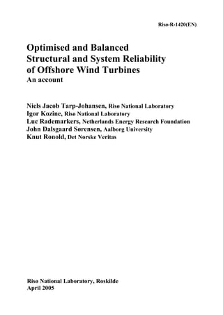
The most probable number of collapses given the control/safety system fails is
as much as three times higher than the number given the control/safety system
work properly: 21 against 7. Thus there is an indication that an unbalance be-
tween system reliability and structural reliability for older turbines. If one takes
the most probable number of collapses the unbalance is remarkably higher in
the storm case, namely an order of magnitude (11 against 1), than in all other
cases pooled together. This seems to support the anticipation that the unbalance
would be more pronounced at extreme wind speeds.
28 Risø-R-1420(EN)
29. Number of wind turbine collapses
Period 1984-1992 Period 1993-2000 Period 1984-2000
Sit.1 Sit.2 Sit.3 Sit.4 Sit.1 Sit.2 Sit.3 Sit.4 Sit.1 Sit.2 Sit.3 Sit.4
Operational 12437 17425 29862
time (years) (wind turbine years) (wind turbine years) (wind turbine years)
Range of
[0,8] [1,6] [3,12] [5,15] [0,13] [2,7] [2,12] [0,7] [0,21] [3,13] [5,24] [5,22]
uncertainty
Most
1 3 4 7 0 3 7 3 1 6 11 10
probable
Rate of wind turbine collapses (1/year)
Upper bound 6,43E-04 4,82E-04 9,65E-04 1,21E-03 7,46E-04 4,02E-04 6,89E-04 4,02E-04 7,03E-04 4,35E-04 8,04E-04 7,37E-04
Lower bound 0,00E+00 8,04E-05 2,41E-04 4,02E-04 0,00E+00 1,15E-04 1,15E-04 0,00E+00 0,00E+00 1,00E-04 1,67E-04 1,67E-04
Most
8,04E-05 2,41E-04 3,22E-04 5,63E-04 0,00E+00 1,72E-04 4,02E-04 1,72E-04 3,35E-05 2,01E-04 3,68E-04 3,35E-04
probable
Upper bound 3,30E-03 2,24E-03 2,68E-03
Lower bound 7,24E-04 2,30E-04 4,35E-04
Most
1,21E-03 7,46E-04 9,38E-04
probable
Table 3: statistics for wind turbine collapses
1,00E-04 1,14E-03
1984 - 2000
3,35E-04 1,54E-03
1,15E-03
1993 - 2000
1,15E-04 1,15E-04 1,09E-03
1,13E-03
1984 - 1992
8,04E-05 5,63E-04 2,17E-03
The red arches stand for Sit.1 + Sit.2, i.e. the SS was properly working
The blue arches stand for Sit.3 + Sit.4, i.e. the SS was failed
Figure 2: graphical representation of interval-valued rates of structural col-
lapses of wind turbines
The interval-valued rate of collapses irrespective of the conditioning events is
[4.35E-04, 2.68E-03] (1/year), and the most probable rate is 9.38E-04 (1/year).
Remarkably a slightly different analysis performed on a data set provided by
ISET [17] supports, by and large, the conclusions reached above. However, it is
notable that especially in the EMD data set 1984 – 1992 many failures are re-
ported that have to do with “unfortunate design, manufacturing, and operation”.
Other data sets show less of such failures. It should be noted that all four situa-
tions in fact give rise to conditional failure rates. If we assume that wind speeds
above say 25 m/s (10-min. averages) occur only less than 0.5 times a year, the
29 Risø-R-1420(EN)
30. failure rates given the high wind speeds are higher than what we conclude here.
The failure records did however not give information on climate, why the con-
ditional failure rates have not been assessed. Furthermore reporting failure oc-
casions to the database administrated by the EMD company is voluntary and we
may expect that not all failures are recorded in the database. For example, data
on failure occasions collected at Risø are complementary to EMD’s database.
Thus, despite the additional source of failure data, one can truly conclude that
the reliability assessments exhibited in the current report have to be considered
optimistic.
3.3 Forecasting system reliabilities
The analysis in the previous section was based on older onshore turbines. They
indicated that an unbalance between system reliability and structural reliability
is present for the older turbines. To move from the results of this analysis to an
investigation of the possible existence of an unbalance between system reliabil-
ity and structural reliability for offshore wind turbines is quite a delicate matter.
There is no doubt that the wind turbine engineering community has learned
from previous experience. On the other hand new technical challenges con-
stantly emerge, especially as one moves offshore.
As discussed already in section 3.2.1 it is difficult to give guidance on how to
forecast the balance between system and structural reliability. The simplest way
would be to estimate from the observed data, which span approximately 15
years, the failure rates in the first 7 years and the last 7 years to see if a trend
may be observed. If a trend is observed then one may simply extrapolate line-
arly ahead from these results to present time and then possibly correct for the
expectable jump-like increase in failure rates as one moves offshore. Baring in
mind the ambiguity of the data, the data is insufficient to draw solid conclusions
on trends, why estimates based on observed possible trend would have to be
‘taken with a grain of salt’. Thus trying to make a correction for the jump in
failure rates that one may expect as wind turbines are moved offshore does not
make much sense as a quantification of this jump is itself quite difficult.
Though it is strictly not meaningful to make a forecast an estimate is anyways
produced in order to have some idea about the possible development. Due to the
observed fact of independence of the blade failures of the state of the con-
trol/safety system the forecast will be based solely on observed WTB collapses,
i.e. Table 3. From this table it follows that the most probable failure rate given
the control/safety system fails is 11/12437 ≈ 8.8 ⋅ 10−4 yr −1 for the period 1984-
1992 and 10 /17425 ≈ 5.7 ⋅ 10−4 yr −1 for the period 1993-2000, when regarding
both normal and extreme weather conditions. Thus trend in these data is
8.8 / 5.7 ≈ 1.5 in the direction of increased system reliability. This is not a strong
trend, however it leads to a forecasted failure rate given the control/safety sys-
tem fails, which is 5.7 ⋅ 10−4 yr −1 /1.5 ≈ 3.8 ⋅ 10−4 yr -1 in the time period 2000-
2007. This forecast should be compared to the failure rate given that the con-
trol/safety system works properly. Assuming that this rate should be more or
less constant in time an estimate is obtained by considering the entire period
1984-2000, for which the most probable failure rate given that the control/safety
system works properly is 7 / 29862 ≈ 2.3 ⋅ 10−4 yr −1 . If one believes in the fore-
cast, it shows that an unbalance between system and structural reliability will
prevail, even if one neglects the, admittedly, possibly small jump-like increase
in failure rate due to the change from onshore to offshore environment. On the
other hand there is among the project participants anticipation that the im-
30 Risø-R-1420(EN)
31. provement of the wind turbine technology has not followed a linear trend but
more likely a more rapidly growing trend. Thus it is expected, but not docu-
mented, that the balance will not be as pronounced as the simple forecast pre-
dicts, not to say that there will not be an unbalance at all. Further control/safety
system failures will probably predominantly be due to random failures rather
than unfortunate design.
From the investigations ECN made during the project “Handbook Determining
Risk Zones for Wind Turbines” [11] in the Netherlands they concluded, as is
done in this report too, that the EMD and ISET data are insufficiently detailed
to draw conclusions on trends. However, the failure rate “loss of blades” deter-
mined in the beginning of the nineties was approximately 2,6⋅10-3 per year. The
failure rate used now (based on the EMD and ISET data until 2000) shows a
95% upper limit of 8,4⋅10-4 per year. Thus an improvement of 3,1 seems to be
realised. Though “loss of blades” is “another business” than control/safety sys-
tem the apparent improvement of “loss of blades” also gives an indication of the
wind turbine industry’s capability of improving design.
If one accepts that there is at present days still an unbalance between system and
structural reliability and if one expects that there is little to do about improving
system reliability, one may turn the situation around and ask if the over-all reli-
ability is acceptable? If yes, there will then be room for reductions of the struc-
tural reliability without compromising the overall reliability significantly, espe-
cially in the storm situation. This is a question to be answered by society and
not by the authors of this report. One may say that society implicitly has ac-
cepted the present level of over-all reliability as it accepts to continuous erection
of wind turbines. Whether it will be feasible to reduce the structural reliability
level is further discussed in Section 4.3.
3.4 Gaining more insight from the data analysis
and developed approach
It was in the analysis presented in the previous section realised that the biggest
problem is ambiguity of the data. This section presents an example for which
some of the presumptions may be debatable but none the less it is demonstrated
what kind of conclusions one could arrive at if the system of failure reporting
was reliable. Thus, much more insight would be possible to gain if the failures
were properly and unambiguously reported.
By looking into formula (5) we can conclude that varying the probabilities of
failure of the CS will have different affect compared to varying the probabilities
characterising the structural reliability. To make this point more clear, let us
consider an example of what kind of insight one can get by analysing the prob-
abilities of wind turbine collapses. The data for this example are taken from
Table 3 for the period 1984-2000.
For the sake of simplicity and of being specific, let us take for this example the
probabilities of the four situations happening judged as most probable values.
These probabilities are found in the right lower corner of Table 3. Write them as
follows
31 Risø-R-1420(EN)
32. Pr(Sit. 1) = Pr( SF | CS and Dstorm ) Pr(CS | Dstorm ) Pr( Dstorm ) = 3.35 ⋅ 10−5
Pr(Sit. 2) = Pr( SF | CS and Dstorm ) Pr(CS | Dstorm ) Pr( Dstorm ) = 2.01 ⋅ 10−4
(6)
Pr(Sit. 3) = Pr( SF | CS and Dstorm ) Pr(CS | Dstorm ) Pr( Dstorm ) = 3.68 ⋅ 10−4
Pr(Sit. 4) = Pr( SF | CS and Dstorm ) Pr(CS | Dstorm ) Pr( Dstorm ) = 3.35 ⋅ 10−4
For the storm situation (situations 1 and 3) it is apparent that an improvement of
the reliability of the CS will have the larges impact on the over-all reliability. In
order to give a quantitative example we need some assumptions. Let us assume
that the probability of having a storm (wind speeds above 25 m/s) per year is
approximately equal to 0.5. This figure can be interpreted in a different way as
having such a storm every second year in average, which seems to our knowl-
edge a realistic assumption for hub heights about 30 to 70 meters in a north
European environment. Another assumption introduced is that of the WTB suf-
fers a major structural failure (collapse) with surety given the CS does not prop-
erly work during a storm. Formally, this means that Pr( SF | CS and Dstorm ) = 1 .
Thus, applying these two assumptions to Pr(Sit. 3) we arrive at an equality
Pr(Sit. 3) = 1 ⋅ Pr(CS | Dstorm ) ⋅ 0.5 = 3.68 ⋅ 10−4 (7)
from which we derive that Pr(CS | Dstorm ) = 7.36 ⋅ 10−4 . Using also that
Pr(CS | Dstorm ) = 1 − Pr(CS | Dstorm ) a value for Pr( SF | CS and Dstorm ) can be
derived. Thus, all together, we have for the storm situations:
Pr(Sit. 1) = 6.70 ⋅ 10−5 ⋅ 0.999264 ⋅ 0.5 = 3.35 ⋅ 10−5
(8)
Pr(Sit. 3) = 1 ⋅ 7.36 ⋅ 10−4 ⋅ 0.5 = 3.68 ⋅ 10−4
First, let us see what would be the effect of reducing the unreliability of the CS
as much as two times. That is, we are going to substitute the probability
Pr(CS | Dstorm ) = 7.36 ⋅ 10−4 with Pr(CS | Dstorm ) = 3.68 ⋅ 10−4 . Recalculating the
probabilities of situation 1 and 3 brings us to the following result
Pr(Sit. 1) + Pr(Sit. 3) = 3.35 ⋅ 10−5 + 1.84 ⋅ 10−4 = 2.17 ⋅ 10−4 (9)
which shows an improvement a little below 2 times relative to the figure that
appear in (6), as it is situation 3 that gives rise to the dominant contribution to
the over-all reliability in the storm situation. Had not only the storm situation
but all situations been considered, the gain would not have been as pronounced
because the rates of failure in the two non-storm situations, 2 and 4, are of the
same magnitude as in situation 3.
Next let us see what would be the effect of reducing the probability of major
structural failures of WTBs given the unreliability of the CS remains untouched,
i.e., Pr(CS | Dstorm ) = 3.68 ⋅ 10−4 . This case is somewhat more complicated com-
pared to the previous. We assume that the improvements of structural reliability
are directed to have the WTB more durable given the CS properly works. This
also means that the structural improvements are not directed to compensate the
unreliability of the CS by having a more strong structure. That is, the aim is to
see how the reduction of the probability Pr( SF | CS and Dstorm ) would affect the
32 Risø-R-1420(EN)
33. probability Pr( SF and Dstorm ) . Reducing this probability by two times gives the
number Pr( SF | CS and Dstorm ) = 3.35 ⋅ 10−5 (i.e. half the first factor in the equa-
tion in (8)) and consequently
Pr(Sit. 1) + Pr(Sit. 3) = 1.68 ⋅10−5 + 3.68 ⋅ 10−4 = 3.85 ⋅ 10−4 (10)
This result means that the improvements directed to reduce the structural unreli-
ability as much as two times, provided the CS works properly, would reduce the
probability of having collapse by approximately 1,05 times. That is, the effect
of raising the reliability of the CS is clearly higher than that of raising structural
reliability.
One could now proceed to evaluate the costs of providing both a higher reliabil-
ity of the CS and the structure. Based on the costs evaluated and the probabili-
ties assessed it would not be a problem to make the right decision with respect
to which measures are more effective and beneficial.
33 Risø-R-1420(EN)
35. 4 Structural Reliability
This chapter considers the structural reliabilities of wind turbines. The main
work and results obtained within this project are reported in the project reports
[21], [26], and in the proceedings paper [25]. In these documents further refer-
ences to relevant documents are given. This chapter mainly sums up the prereq-
uisites and conclusions of the work and compares them with the results obtained
in Chapter 3. This work focuses mainly on describing aerodynamic loads. In the
project an effort has also been made to obtain information about hydrodynamic
loads. A section below recapitulates the findings. Finally the chapter gives an
illustrative example on cost-optimal structural reliability of offshore wind tur-
bines. For the sake of completeness it is emphasised that strictly speaking fail-
ure rates of structural collapses reported in Chapter 3 represent the tower, foun-
dation and other structural components regarded as a system, whereas in the
present chapter regards only component reliabilities. However, the structural
system has little redundancy, i.e. it is almost of series type with few main com-
ponents, implying that the system reliability is expected not deviate much from
the component reliabilities computed in the present chapter.
In the project an attempt to evaluate the structural reliability of current wind
turbines by use theoretical means has been made for the reason of comparing
with observed system reliability data. As explained in Chapter 2 this evaluation
gives results, which are notional, i.e. they cannot be expected to fit with ob-
served failure rates. However observing these low failure rates is actually not
possible unless many, many years of data is available. Therefore it has been de-
cided to make a theoretical assessment in spite of its drawbacks. It has shown to
be so that there is an unfortunate balance between structural reliability and sys-
tem reliability. There are two “handles to twist” to solve this problem: system
reliability can be increased and structural reliability can be decreased. The rela-
tive increase and decrease will of course depend on what will be the target of
the over-all reliability (i.e. the combined structural and system reliability). It
will also depend on what will be the costs spent and savings gained by the in-
crease in system reliability and decrease in structural reliability, respectively. In
order to get an idea about the possible target over-all reliability evaluation of
cost-optimal structural reliabilities have been made in the project. As explained
below in Section 4.3 this is especially relevant for offshore wind turbines. These
cost-optimal structural reliabilities are also of notional type.
4.1 Structural Reliability – Aerodynamic Loads
As decided in Chapter 3 an estimate of the structural reliability of a turbine un-
der the extreme aerodynamic storm load has been regarded. This load case ap-
pears in both structural design codes and in wind turbine design codes. Thus
comparing with reliability levels of structural codes will be possible. The reli-
ability levels are computed as the average of the reliabilities for a steel compo-
nent, a FRP component and a concrete component.
The results reported here are documented in [21]. However a few formulas are
repeated for easy reference. Following derivations very similar to those in Sec-
tion 4.3 below it is in [21] shown that the structural reliability (the complement
35 Risø-R-1420(EN)
36. Name Description Type COV. Char.
Value
P Annual max. mean wind pressure G 23% 98%
I Turbulence intensity LN 5% µ =1
Table 4: inherent uncertainties of external ultimate loads. The percentages ap-
pearing in the last column are the percentiles that define the characteristic va-
lue.
of the probability of failure p f ) of a wind turbine structure, which is designed
to the limit according to a given standard, can be computed according to for-
mula (11) on the next page.
1 − p f = Pr{γ mγ f Σ X R ≥ P[η + (1 − η ) IX dyn ] X exp X st X aero X str X sim } (11)
In the above formula γ m and γ f are material and load partial safety factors,
respectively, Σ is the material strength normalised by its characteristic value
(typically 5% percentile), X R accounts for model uncertainties related to the
material modelling, P is the annual max. 10 min. mean wind velocity pressure
at hub-height normalised by its characteristic value (the 98% percentile), I de-
notes the turbulence intensity, X dyn , X exp , X st , X aero , X str , and X sim are all
model uncertainties related to the aerodynamic loads. The factor X dyn accounts
for model uncertainties stemming from the modelling of the dynamical response
characteristics of the turbine, e.g. structural damping ratios and eigenfrequen-
cies. The factor X exp accounts for the model uncertainties associated with the
exposure coefficient, i.e. X exp accounts for the uncertainties due to the model-
ling of terrain topography and roughness. Statistical uncertainty connected with
the assessment of the wind climate is accounted for by the factor X st . The fac-
tor X aero accounts for model uncertainties related to the assessment of the lift
Name Description Type COV. Char.
Normal Low Value
X exp Exposure (terrain) LN 20% 10% µ =1
X st Climate statistics LN 10% 5% µ =1
Shape factor / model µ =1
X aero G 20% 10%
scale
X dyn Structural dynamics LN 20% 5% µ =1
X str Stress evaluation LN 3% µ =1
X sim Simulation statistics N From simulation COV. µ =1
Table 5: model and statistical uncertainties for ultimate load. The COV-column
is subdivided: the left sub column is referred to as normal uncertainties,
whereas the right sub column is referred to at low model uncertainties – [21]
discusses the differences .In the last column the notation means that the charac-
teristic value is defined by the expectance, which is put equal to 1.
36 Risø-R-1420(EN)