Download as PDF, PPTX


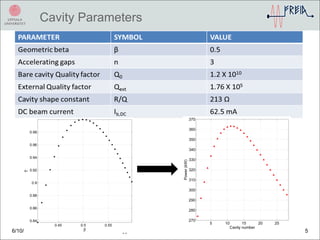
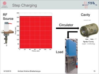
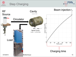
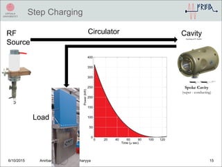
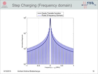
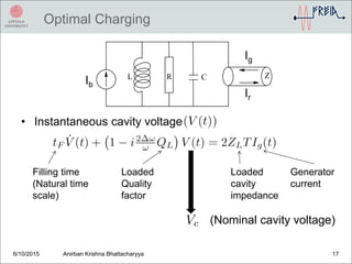
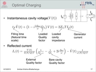
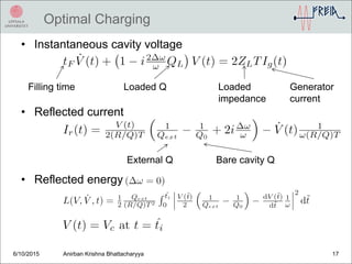
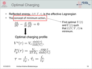
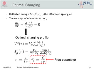
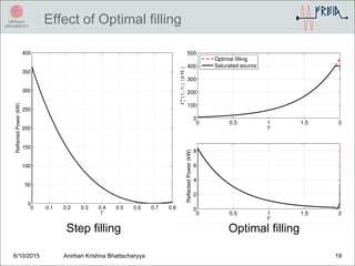
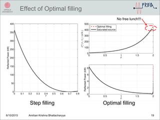
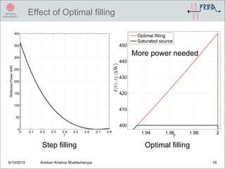
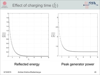
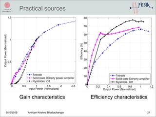
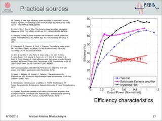
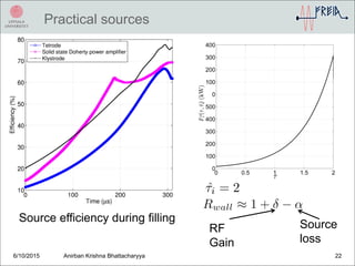
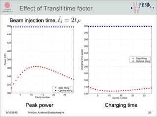
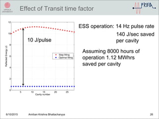


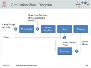
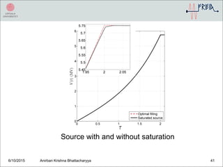
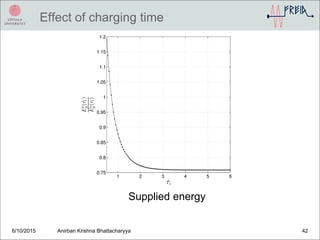
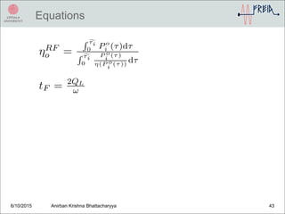

This document discusses optimizing the charging of superconducting cavities to minimize reflected energy. It presents that the optimal charging profile can be determined by finding the charging curve that minimizes the reflected energy, which is treated as an effective Lagrangian. Simulations show that using the optimal profile requires more power from the RF source but reduces reflected energy compared to step charging. Accounting for practical sources like klystrons and their efficiency variations is also important to determine the best charging strategy.


![Power[1]](https://cdn.slidesharecdn.com/ss_thumbnails/power1-140206134810-phpapp01-thumbnail.jpg?width=640&height=640&fit=bounds)


![[IJET-V1I2P6] Authors :Sarat K Kotamraju, K.Ch.Sri Kavya, A.Gnandeep Reddy, G...](https://cdn.slidesharecdn.com/ss_thumbnails/ijet-v1i2p6-150501052009-conversion-gate02-thumbnail.jpg?width=640&height=640&fit=bounds)

![RF Module Design - [Chapter 6] Power Amplifier](https://cdn.slidesharecdn.com/ss_thumbnails/rfch6-150613070347-lva1-app6891-thumbnail.jpg?width=640&height=640&fit=bounds)


