OPTICS: BASICS CONCEPTS
MdAnisur Rahman (Anjum)
Professor & Head of the department
(Ophthalmology)
Dhaka Medical College, Dhaka
2.
What is opticalscience.
Optical science. Though most people associate the word
‘optics’ with the engineering of lenses for eyeglasses,
telescopes, and microscopes,
In physics the term more broadly refers to the study of
the behavior of light and its interactions with matter.
3.
Three broad subfieldsof optics
1) Geometrical optics, the study of light as rays
2) Physical optics, the study of light as waves
3) Quantum optics, the study of light as particles
4.
Geometrical optics
Light ispostulated to travel along rays – line
segments which are straight in free space but may
change direction, or even curve, when encountering
matter.
5.
Geometrical optics
Two lawsdictate what happens when light encounters
a material surface. The law of reflection, evidently
first stated by Euclid around 300 BC, states that when
light encounters a flat reflecting surface the angle of
incidence of a ray is equal to the angle of reflection.
6.
1. Geometrical optics
•The law of refraction, experimentally determined by
Willebrord Snell in 1621, explains the manner in
which a light ray changes direction when it passes
across a planar boundary from one material to
another.
7.
From the lawsof reflection and refraction:
One can determine the behavior of optical devices
such as telescopes and microscopes.
One can trace the paths of different rays (known as
‘ray tracing’) through the optical system
8.
How imagescan be formed?
Their relative orientation, and their magnification.
This is in fact the most important use of geometrical
optics to this day: the behavior of complicated optical
systems can, to a first approximation, be determined
by studying the paths of all rays through the system.
10.
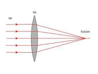
2. Physical optics
Lookingagain at the ray picture of focusing above, we
run into a problem: at the focal point, the rays all
intersect. The density of rays at this point is therefore
infinite, which according to geometrical optics
implies an infinitely bright focal spot. Obviously, this
cannot be true.
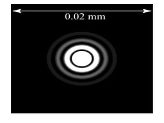
11.
• If weput a black screen in the plane of the focal point
and look closely at the structure of the focal spot
projected on the plane, experimentally we would see
an image as simulated below:
13.
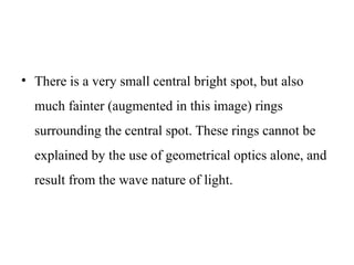
• There isa very small central bright spot, but also
much fainter (augmented in this image) rings
surrounding the central spot. These rings cannot be
explained by the use of geometrical optics alone, and
result from the wave nature of light.
14.
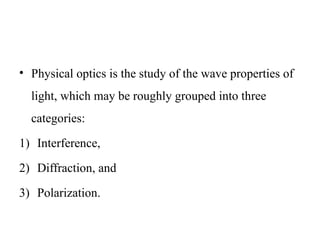
• Physical opticsis the study of the wave properties of
light, which may be roughly grouped into three
categories:
1) Interference,
2) Diffraction, and
3) Polarization.
15.
Interference
Interference isthe ability of a wave to interfere with
itself, creating localized regions where the field is
alternately extremely bright and extremely dark.
Quantum optics
We returnto the picture of the focal spot illustrated
above and now imagine that the light source which
produces the focal spot is on a very precise dimmer
switch. What happens as we slowly turn the dimmer
switch down to the off position?
19.
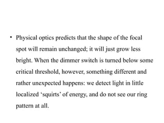
• Physical opticspredicts that the shape of the focal
spot will remain unchanged; it will just grow less
bright. When the dimmer switch is turned below some
critical threshold, however, something different and
rather unexpected happens: we detect light in little
localized ‘squirts’ of energy, and do not see our ring
pattern at all.
20.
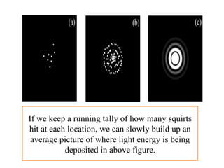
If we keepa running tally of how many squirts
hit at each location, we can slowly build up an
average picture of where light energy is being
deposited in above figure.
21.
May 29, 2025anjumk38dmc@gmail.com 21
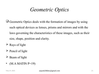
Geometric Optics
Geometric Optics deals with the formation of images by using
such optical devices as lenses, prisms and mirrors and with the
laws governing the characteristics of these images, such as their
size, shape, position and clarity.
Rays of light
Pencil of light
Beam of light
• (M.A MATIN P=19)
22.
Reflection
The lawof reflection, evidently first stated by Euclid
around 300 BC, states that when light encounters a
flat reflecting surface the angle of incidence of a ray
is equal to the angle of reflection
23.
May 29, 2025anjumk38dmc@gmail.com 23
Reflection of light
• When light meets an interface between two media, its
behavior depends on the nature of the two media
involved. Light may be absorbed by the new medium
or transmitted onward through it or it may bounch
back into first medium. This bouncing of light at an
interface is called Reflection.
(M.A MATIN = 21)
24.
Q. What happenedto the light when
it strikes a surface?
Ans) 3 things may happen. It may be:
Absorbed
Reflected
Or Refracted
25.
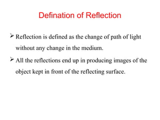
Defination of Reflection
Reflection is defined as the change of path of light
without any change in the medium.
All the reflections end up in producing images of the
object kept in front of the reflecting surface.
26.
May 29, 2025anjumk38dmc@gmail.com 26
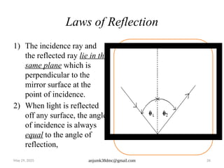
Laws of Reflection
1) The incidence ray and
the reflected ray lie in the
same plane which is
perpendicular to the
mirror surface at the
point of incidence.
2) When light is reflected
off any surface, the angle
of incidence is always
equal to the angle of
reflection,
27.
May 29, 2025anjumk38dmc@gmail.com 27
Mirror
• A mirror is optical media which reflects light
backwards when fall on it. It may be:
1) Plane mirrors or
2) Spherical mirrors.
28.
May 29, 2025anjumk38dmc@gmail.com 28
Mirror: Rules for rays tracing through a
mirror
1) The ray which pass through the pole shall pass
undeviated.
2) The ray which is parallel with the axis shall pass
through the focal point after convergence or
divergence.
3) The ray passing through the focal point & falling on
the mirror surface shall pass parallel to the optical
axis.
4) The ray passing through the centre of curvature of a
mirror shall also pass undeviated.
5) Path of light rays are also reversible.
29.
May 29, 2025anjumk38dmc@gmail.com 29
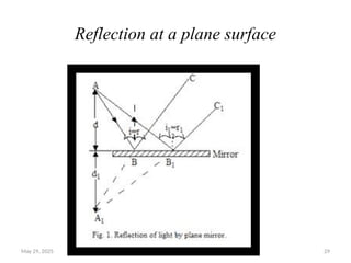
Reflection at a plane surface
30.
May 29, 2025anjumk38dmc@gmail.com 30
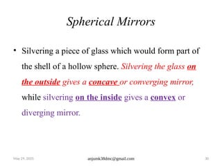
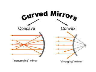
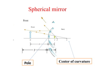
Spherical Mirrors
• Silvering a piece of glass which would form part of
the shell of a hollow sphere. Silvering the glass on
the outside gives a concave or converging mirror,
while silvering on the inside gives a convex or
diverging mirror.
32.
Types of images
There are two types of images formed mirrors. They
are:
• 1) Virtual image.
• 2) Real image.
33.
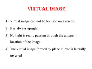
Virtual image
1) Virtualimage can not be focused on a screen.
2) It is always upright.
3) No light is really passing through the apparent
location of the image.
4) The virtual image formed by plane mirror is laterally
inverted
34.
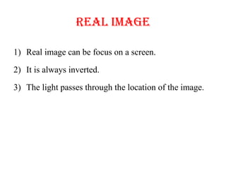
Real image
1) Realimage can be focus on a screen.
2) It is always inverted.
3) The light passes through the location of the image.
35.
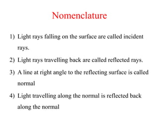
Nomenclature
1) Light raysfalling on the surface are called incident
rays.
2) Light rays travelling back are called reflected rays.
3) A line at right angle to the reflecting surface is called
normal
4) Light travelling along the normal is reflected back
along the normal
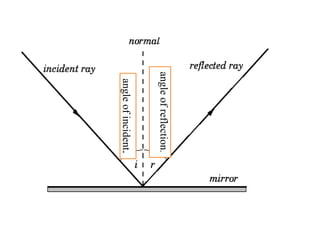
Nomenclature
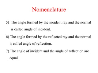
5) The angleformed by the incident ray and the normal
is called angle of incident.
6) The angle formed by the reflected ray and the normal
is called angle of reflection.
7) The angle of incident and the angle of reflection are
equal.
38.
Nomenclature
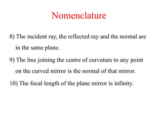
8) The incidentray, the reflected ray and the normal are
in the same plane.
9) The line joining the centre of curvature to any point
on the curved mirror is the normal of that mirror.
10) The focal length of the plane mirror is infinity.
39.
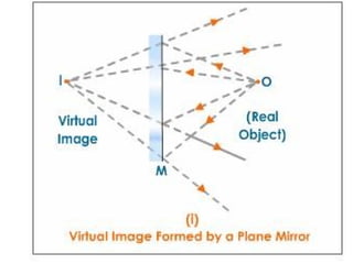
Image formation byplain mirror
If the reflecting surface of the mirror is flat then we
call this type of mirror as plane mirrors. Light always
has regular reflection on plane mirrors.
Given picture below shows how we can find the
image of a point in plane mirrors.
41.
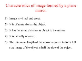
Characteristics of imageformed by a plane
mirror.
1) Image is virtual and erect.
2) It is of same size as the object.
3) It has the same distance as object to the mirror.
4) It is laterally reversed.
5) The minimum length of the mirror required to form full
size image of the object is half the size of the object.
42.
Number of images
Howmany images can you form by two plane
mirror?
It depends upon the inclination of two mirrors with
each other.
• The number of images formed by two plane mirrors
inclined to each other is calculated by the formula:
43.
Number of images
•N=360/ - 1 (Here, N = number of images form, is
ᴓ ᴓ
the angle between two mirrors)
• Less the angle between two mirrors, more the number
of images.
44.
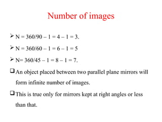
Number of images
N = 360/90 – 1 = 4 – 1 = 3.
N = 360/60 – 1 = 6 – 1 = 5
N= 360/45 – 1 = 8 – 1 = 7.
An object placed between two parallel plane mirrors will
form infinite number of images.
This is true only for mirrors kept at right angles or less
than that.
45.
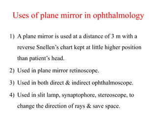
Uses of planemirror in ophthalmology
1) A plane mirror is used at a distance of 3 m with a
reverse Snellen’s chart kept at little higher position
than patient’s head.
2) Used in plane mirror retinoscope.
3) Used in both direct & indirect ophthalmoscope.
4) Used in slit lamp, synaptophore, stereoscope, to
change the direction of rays & save space.
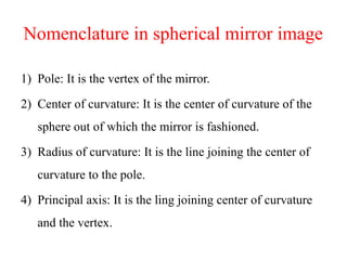
Nomenclature in sphericalmirror image
1) Pole: It is the vertex of the mirror.
2) Center of curvature: It is the center of curvature of the
sphere out of which the mirror is fashioned.
3) Radius of curvature: It is the line joining the center of
curvature to the pole.
4) Principal axis: It is the ling joining center of curvature
and the vertex.
48.
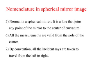
Nomenclature in sphericalmirror image
5) Normal in a spherical mirror: It is a line that joins
any point of the mirror to the center of curvature.
6) All the measurements are valid from the pole of the
center.
7) By convention, all the incident rays are taken to
travel from the left to right.
49.
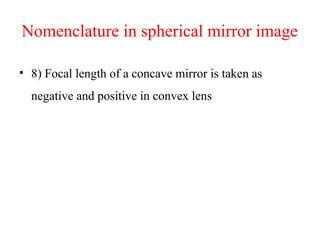
Nomenclature in sphericalmirror image
• 8) Focal length of a concave mirror is taken as
negative and positive in convex lens
50.
May 29, 2025anjumk38dmc@gmail.com 50
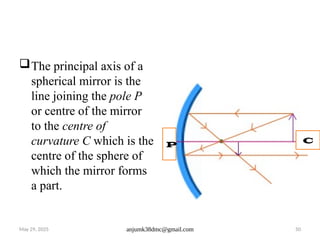
The principal axis of a
spherical mirror is the
line joining the pole P
or centre of the mirror
to the centre of
curvature C which is the
centre of the sphere of
which the mirror forms
a part.
P C
51.
May 29, 2025anjumk38dmc@gmail.com 51
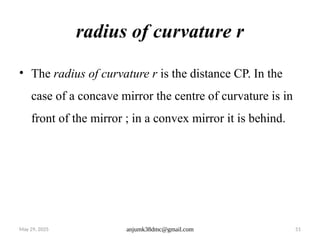
radius of curvature r
• The radius of curvature r is the distance CP. In the
case of a concave mirror the centre of curvature is in
front of the mirror ; in a convex mirror it is behind.
52.
May 29, 2025anjumk38dmc@gmail.com 52
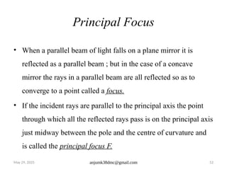
Principal Focus
• When a parallel beam of light falls on a plane mirror it is
reflected as a parallel beam ; but in the case of a concave
mirror the rays in a parallel beam are all reflected so as to
converge to a point called a focus.
• If the incident rays are parallel to the principal axis the point
through which all the reflected rays pass is on the principal axis
just midway between the pole and the centre of curvature and
is called the principal focus F.
53.
May 29, 2025anjumk38dmc@gmail.com 53
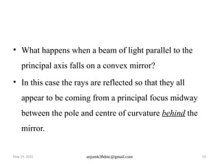
• What happens when a beam of light parallel to the
principal axis falls on a convex mirror?
• In this case the rays are reflected so that they all
appear to be coming from a principal focus midway
between the pole and centre of curvature behind the
mirror.
54.
May 29, 2025anjumk38dmc@gmail.com 54
• A concave mirror, therefore has a real principal focus,
while the convex mirror has a virtual one.
• The focal length of a spherical mirror is half its radius
of curvature.
55.
May 29, 2025anjumk38dmc@gmail.com 55
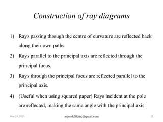
Construction of ray diagrams
• Since a point on an image can be located by the point of
intersection of two reflected rays, we have to consider which
are the most convenient rays to use for this purpose.
• Remembering that, by geometry, the normal to a curved
surface at any point is the radius of curvature at that point, one
very useful ray to draw will be one which is incident along a
radius of curvature. Since this is incident normally on the
mirror, it will be reflected back along its own path.
56.
May 29, 2025anjumk38dmc@gmail.com 56
Construction of ray diagrams
• Another useful ray is one which falls on the mirror parallel to
the principal axis. By definition, this will be reflected through
the principal focus. Conversely, any incident ray passing
through the principal focus will be reflected back parallel to
the principal axis. The same observations also apply to the
convex mirrors, so we may briefly sum them up into a set of
rules for constructing images formed by spherical mirrors.
57.
May 29, 2025anjumk38dmc@gmail.com 57
Construction of ray diagrams
1) Rays passing through the centre of curvature are reflected back
along their own paths.
2) Rays parallel to the principal axis are reflected through the
principal focus.
3) Rays through the principal focus are reflected parallel to the
principal axis.
4) (Useful when using squared paper) Rays incident at the pole
are reflected, making the same angle with the principal axis.
58.
May 29, 2025anjumk38dmc@gmail.com 58
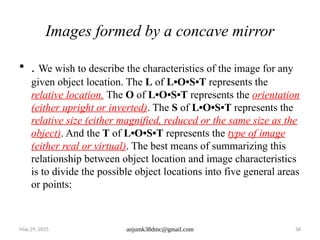
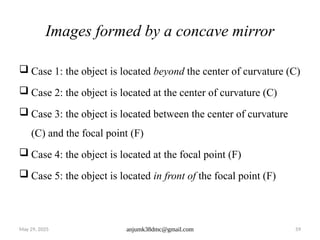
Images formed by a concave mirror
• . We wish to describe the characteristics of the image for any
given object location. The L of L•O•S•T represents the
relative location. The O of L•O•S•T represents the orientation
(either upright or inverted). The S of L•O•S•T represents the
relative size (either magnified, reduced or the same size as the
object). And the T of L•O•S•T represents the type of image
(either real or virtual). The best means of summarizing this
relationship between object location and image characteristics
is to divide the possible object locations into five general areas
or points:
59.
May 29, 2025anjumk38dmc@gmail.com 59
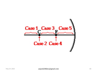
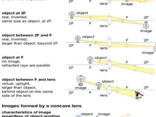
Images formed by a concave mirror
Case 1: the object is located beyond the center of curvature (C)
Case 2: the object is located at the center of curvature (C)
Case 3: the object is located between the center of curvature
(C) and the focal point (F)
Case 4: the object is located at the focal point (F)
Case 5: the object is located in front of the focal point (F)
May 29, 2025anjumk38dmc@gmail.com 61
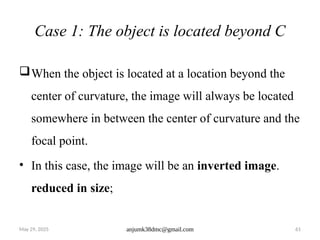
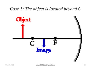
Case 1: The object is located beyond C
When the object is located at a location beyond the
center of curvature, the image will always be located
somewhere in between the center of curvature and the
focal point.
• In this case, the image will be an inverted image.
reduced in size;
62.
May 29, 2025anjumk38dmc@gmail.com 62
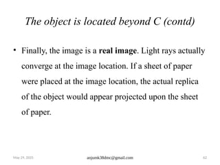
The object is located beyond C (contd)
• Finally, the image is a real image. Light rays actually
converge at the image location. If a sheet of paper
were placed at the image location, the actual replica
of the object would appear projected upon the sheet
of paper.
63.
May 29, 2025anjumk38dmc@gmail.com 63
Case 1: The object is located beyond C
64.
May 29, 2025anjumk38dmc@gmail.com 64
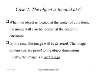
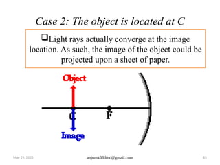
Case 2: The object is located at C
When the object is located at the center of curvature,
the image will also be located at the center of
curvature.
In this case, the image will be inverted. The image
dimensions are equal to the object dimensions.
Finally, the image is a real image.
65.
May 29, 2025anjumk38dmc@gmail.com 65
Case 2: The object is located at C
Light rays actually converge at the image
location. As such, the image of the object could be
projected upon a sheet of paper.
66.
May 29, 2025anjumk38dmc@gmail.com 66
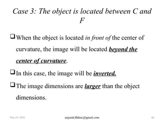
Case 3: The object is located between C and
F
When the object is located in front of the center of
curvature, the image will be located beyond the
center of curvature.
In this case, the image will be inverted.
The image dimensions are larger than the object
dimensions.
67.
May 29, 2025anjumk38dmc@gmail.com 67
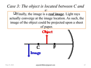
Case 3: The object is located between C and
F
Finally, the image is a real image. Light rays
actually converge at the image location. As such, the
image of the object could be projected upon a sheet
of paper.
68.
May 29, 2025anjumk38dmc@gmail.com 68
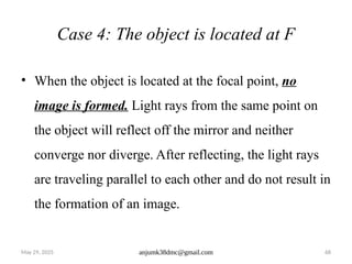
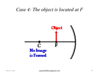
Case 4: The object is located at F
• When the object is located at the focal point, no
image is formed. Light rays from the same point on
the object will reflect off the mirror and neither
converge nor diverge. After reflecting, the light rays
are traveling parallel to each other and do not result in
the formation of an image.
69.
May 29, 2025anjumk38dmc@gmail.com 69
Case 4: The object is located at F
70.
May 29, 2025anjumk38dmc@gmail.com 70
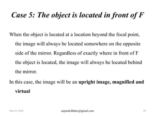
Case 5: The object is located in front of F
When the object is located at a location beyond the focal point,
the image will always be located somewhere on the opposite
side of the mirror. Regardless of exactly where in front of F
the object is located, the image will always be located behind
the mirror.
In this case, the image will be an upright image, magnified and
virtual
71.
May 29, 2025anjumk38dmc@gmail.com 71
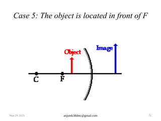
Case 5: The object is located in front of F
72.
May 29, 2025anjumk38dmc@gmail.com 72
Case 5: The object is located in front of F
• This type of image is formed by a shaving or make-up mirror
and also by small concave mirror used by dentists for
examining teeth.
73.
May 29, 2025anjumk38dmc@gmail.com 73
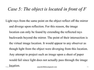
Case 5: The object is located in front of F
Light rays from the same point on the object reflect off the mirror
and diverge upon reflection. For this reason, the image
location can only be found by extending the reflected rays
backwards beyond the mirror. The point of their intersection is
the virtual image location. It would appear to any observer as
though light from the object were diverging from this location.
Any attempt to project such an image upon a sheet of paper
would fail since light does not actually pass through the image
location.
74.
May 29, 2025anjumk38dmc@gmail.com 74
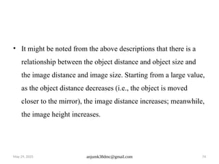
• It might be noted from the above descriptions that there is a
relationship between the object distance and object size and
the image distance and image size. Starting from a large value,
as the object distance decreases (i.e., the object is moved
closer to the mirror), the image distance increases; meanwhile,
the image height increases.
75.
May 29, 2025anjumk38dmc@gmail.com 75
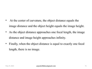
• At the center of curvature, the object distance equals the
image distance and the object height equals the image height.
• As the object distance approaches one focal length, the image
distance and image height approaches infinity.
• Finally, when the object distance is equal to exactly one focal
length, there is no image.
76.
May 29, 2025anjumk38dmc@gmail.com 76
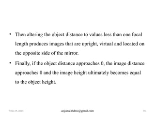
• Then altering the object distance to values less than one focal
length produces images that are upright, virtual and located on
the opposite side of the mirror.
• Finally, if the object distance approaches 0, the image distance
approaches 0 and the image height ultimately becomes equal
to the object height.
77.
May 29, 2025anjumk38dmc@gmail.com 77
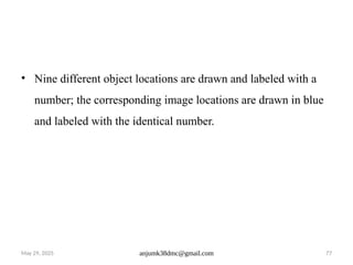
• Nine different object locations are drawn and labeled with a
number; the corresponding image locations are drawn in blue
and labeled with the identical number.
May 29, 2025anjumk38dmc@gmail.com 79
IMAGE
FORM BY
CONVEX
MIRROR
80.
May 29, 2025anjumk38dmc@gmail.com 80
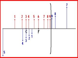
IMAGE FORM BY
CONVEX MIRROR
81.
May 29, 2025anjumk38dmc@gmail.com 81
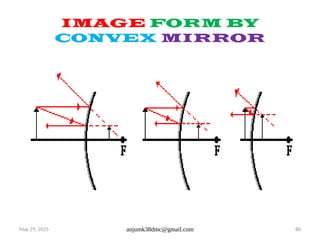
IMAGE FORM BY
CONVEX MIRROR
The diagrams above show that in each case,
the image is
located behind the convex mirror
a virtual image
an upright image
reduced in size (i.e., smaller than the object)
82.
May 29, 2025anjumk38dmc@gmail.com 82
IMAGE FORM BY
CONVEX MIRROR
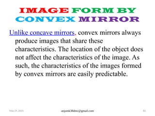
Unlike concave mirrors, convex mirrors always
produce images that share these
characteristics. The location of the object does
not affect the characteristics of the image. As
such, the characteristics of the images formed
by convex mirrors are easily predictable.
83.
May 29, 2025anjumk38dmc@gmail.com 83
IMAGE FORM BY
CONVEX MIRROR
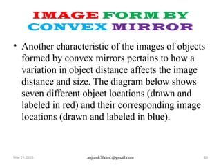
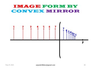
• Another characteristic of the images of objects
formed by convex mirrors pertains to how a
variation in object distance affects the image
distance and size. The diagram below shows
seven different object locations (drawn and
labeled in red) and their corresponding image
locations (drawn and labeled in blue).
84.
May 29, 2025anjumk38dmc@gmail.com 84
IMAGE FORM BY
CONVEX MIRROR
85.
May 29, 2025anjumk38dmc@gmail.com 85
IMAGE FORM BY
CONVEX MIRROR
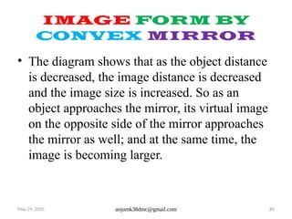
• The diagram shows that as the object distance
is decreased, the image distance is decreased
and the image size is increased. So as an
object approaches the mirror, its virtual image
on the opposite side of the mirror approaches
the mirror as well; and at the same time, the
image is becoming larger.
86.
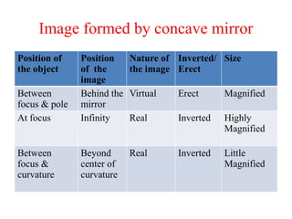
Image formed byconcave mirror
Position of
the object
Position
of the
image
Nature of
the image
Inverted/
Erect
Size
Between
focus & pole
Behind the
mirror
Virtual Erect Magnified
At focus Infinity Real Inverted Highly
Magnified
Between
focus &
curvature
Beyond
center of
curvature
Real Inverted Little
Magnified
87.
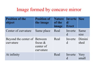
Image formed byconcave mirror
Position of the
object
Position of
the image
Nature
of the
image
Inverte
d/
Erect
Size
Center of curvature Same place Real Inverte
d
Same
size
Beyond the center of
curvature
Between
focus &
center of
curvature
Real Inverte
d
Dimini
shed
At infinity Real Inverte
d
Very
small
88.
Image formed byconvex mirror
The image of an object kept in front of the mirror is
formed behind the mirror.
It is smaller than the object , erect and virtual.
The distance between the image and the mirror is less
than between the object and the mirror.
89.
Behavior of imagesin relation to position of
the object
The image formed by CONVEX and PLANE mirrors
are virtual
The image formed by CONCAVE mirrors can
be real or virtual
The distance between mirror and the image is least in
CONVEX mirror, most in CONCAVE mirror and
equal in PLANE mirror
90.
specular reflection &diffuse reflection
Reflection of smooth surfaces such as mirrors or a
calm body of water leads to a type of reflection
known as specular reflection.
Reflection of rough surfaces such as clothing, paper,
and the asphalt roadway leads to a type of reflection
known as diffuse reflection.
91.
• Whether thesurface is microscopically rough or
smooth has a tremendous impact upon the subsequent
reflection of a beam of light.
92.
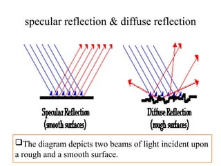
specular reflection &diffuse reflection
The diagram depicts two beams of light incident upon
a rough and a smooth surface.
93.
Applications of Specularand Diffuse
Reflection
There are several interesting applications of this
distinction between specular and diffuse reflection.
One application pertains to the relative difficulty of
night driving on a wet asphalt roadway compared to a
dry asphalt roadway. Most drivers are aware of the
fact that driving at night on a wet roadway results in
an annoying glare from oncoming headlights.
94.
Applications of Specularand Diffuse
Reflection
The glare is the result of the specular reflection of the
beam of light from an oncoming car. Normally a
roadway would cause diffuse reflection due to its
rough surface. But if the surface is wet, water can fill
in the crevices and smooth out the surface.
95.
Applications of Specularand Diffuse
Reflection
• Rays of light from the beam of an oncoming car hit
this smooth surface, undergo specular reflection and
remain concentrated in a beam. The driver perceives
an annoying glare caused by this concentrated beam
of reflected light.
96.
Applications of Specularand Diffuse
Reflection
A second application of the distinction between
diffuse and specular reflection pertains to the field of
photography. Many people have witnessed in person
or have seen a photograph of a beautiful nature scene
captured by a photographer who set up the shot with a
calm body of water in the foreground.
97.
Applications of Specularand Diffuse
Reflection
The water (if calm) provides for the specular
reflection of light from the subject of the photograph.
98.
Applications of Specularand Diffuse
Reflection
Light from the subject can reach the camera lens
directly or it can take a longer path in which it
reflects off the water before traveling to the lens.
• Since the light reflecting off the water undergoes
specular reflection, the incident rays remain
concentrated (instead of diffusing).
99.
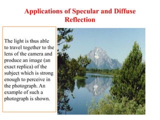
Applications of Specularand Diffuse
Reflection
The light is thus able
to travel together to the
lens of the camera and
produce an image (an
exact replica) of the
subject which is strong
enough to perceive in
the photograph. An
example of such a
photograph is shown.
100.
Question
If a bundleof parallel incident rays undergoing
diffuse reflection follow the law of reflection, then
why do they scatter in many different directions after
reflecting off a surface?
101.
Answer
Each individual raystrikes a surface which has a
different orientation. Since the normal is different for
each ray of light, the direction of the reflected ray
will also be different.
102.
Question
Perhaps you haveobserved magazines which have
glossy pages. The usual microscopically rough
surface of paper has been filled in with a glossy
substance to give the pages of the magazine a smooth
surface. Do you suppose that it would be easier to
read from rough pages or glossy pages? Explain your
answer.
103.
It is mucheasier to read from rough pages which provide
for diffuse reflection. Glossy pages result in specular
reflection and cause a glare. The reader typically sees an
image of the light bulb which illuminates the page. If
you think about, most magazines which use glossy pages
are usually the type which people spend more time
viewing pictures than they do reading articles.
Luminous versus IlluminatedObjects
The objects that we see can be placed into one of two
categories: luminous objects and illuminated objects.
Luminous objects are objects that generate their own
light
Illuminated objects are objects that are capable of
reflecting light to our eyes.
106.
The sun isan example of a luminous object, while the
moon is an illuminated object.
107.
Refraction
Q) What happenedto the light when it strikes a surface?
Ans) 3 things may happen. It may be:
Absorbed
Reflected
Or Refracted
108.
Refraction
Q) What isrefraction?
Ans) Refraction of light is a phenomenon of change in
the path of light when it passes from one medium to
another due to change in velocity.
109.
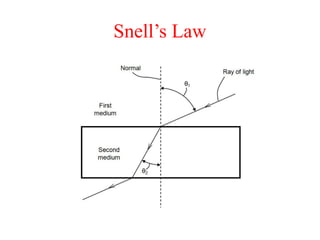
Terms used inrefraction
1) NORMAL: This is a line right angles to the interface
2) INCIDENCE RAY: The ray that strikes the interface
at the base of the normal in an angular fashion.
3) REFRACTED RAY: This is the deviated ray in the
second medium.
110.
4) ANGLE OFINCIDENCE: Angle between the
normal and the incident ray
5) ANGLE OF REFRACTION: The angle between the
refracted ray & the normal is called ANGLE OF
REFRACTION
6) The two angles are never equal.
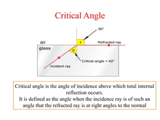
Critical Angle
Critical angleis the angle of incidence above which total internal
reflection occurs.
It is defined as the angle when the incidence ray is of such an
angle that the refracted ray is at right angles to the normal
114.
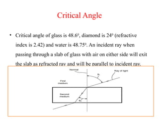
Critical Angle
• Criticalangle of glass is 48.60
, diamond is 240
(refractive
index is 2.42) and water is 48.750
. An incident ray when
passing through a slab of glass with air on either side will exit
the slab as refracted ray and will be parallel to incident ray.
115.
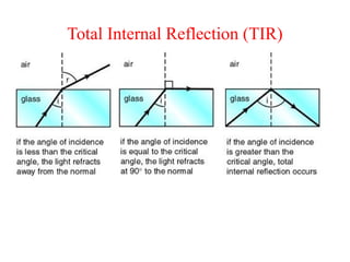
Total Internal Reflection(TIR)
• The complete reflection of a light ray reaching an
interface with a less dense medium when the angle of
incidence exceeds the critical angle.
Different uses ofTIR
1) Gonioscopy employs total internal reflection to view
the anatomical angle formed between the
eye's cornea and iris.
2) Total internal reflection is the operating principle
of optical fibers, which are used in endoscopes and
telecommunications.
118.
Different uses ofTIR
3) Total internal reflection is the operating principle of
automotive rain sensors, which control automatic
windscreen/windshield wipers
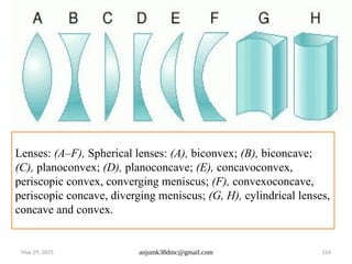
May 29, 2025anjumk38dmc@gmail.com 120
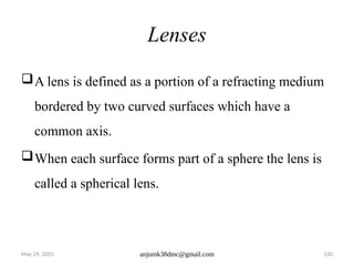
Lenses
A lens is defined as a portion of a refracting medium
bordered by two curved surfaces which have a
common axis.
When each surface forms part of a sphere the lens is
called a spherical lens.
121.
Sometimes, a sphericallens has a one plane surface, it
is acceptable because a plane surface can be thought
of as part of a sphere of infinite radius.
122.
May 29, 2025anjumk38dmc@gmail.com 122
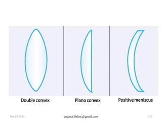
Spherical Lens
Lens may be spherical (when each surface forms part
of sphere, the lens is called a Spherical lens) where
the concavity or convexity two different meridians
are equal.
123.
May 29, 2025anjumk38dmc@gmail.com 123
Cylindrical Lens
It may be cylindrical where there is unequal
concavity in two meridians. The two meridians
usually remains at right angels to each other and the
less curved meridian being designed as axis of the
lens.
May 29, 2025anjumk38dmc@gmail.com 126
Spherical Aberration
The prismatic effect of the peripheral parts of the
spherical lens causes spherical aberration.
It was seen that the prismatic effect of a spherical lens
is least in the paraxial zone and increases towards the
periphery of the lens.
127.
Spherical Aberration
Thus, rayspassing through the periphery of the lens
are deviated more than those passing through the
paraxial zone of the lens.
128.
May 29, 2025anjumk38dmc@gmail.com 128
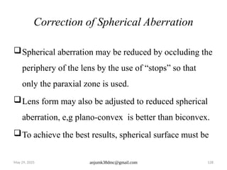
Correction of Spherical Aberration
Spherical aberration may be reduced by occluding the
periphery of the lens by the use of “stops” so that
only the paraxial zone is used.
Lens form may also be adjusted to reduced spherical
aberration, e,g plano-convex is better than biconvex.
To achieve the best results, spherical surface must be
129.
May 29, 2025anjumk38dmc@gmail.com 129
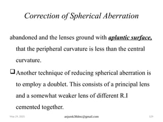
Correction of Spherical Aberration
abandoned and the lenses ground with aplantic surface,
that the peripheral curvature is less than the central
curvature.
Another technique of reducing spherical aberration is
to employ a doublet. This consists of a principal lens
and a somewhat weaker lens of different R.I
cemented together.
130.
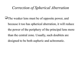
Correction of SphericalAberration
The weaker lens must be of opposite power, and
because it too has spherical aberration, it will reduce
the power of the periphery of the principal lens more
than the central zone. Usually, such doublets are
designed to be both aspheric and achromatic.
131.
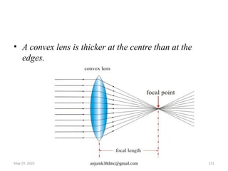
May 29, 2025anjumk38dmc@gmail.com 131
• A convex lens is thicker at the centre than at the
edges.
132.
May 29, 2025anjumk38dmc@gmail.com 132
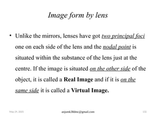
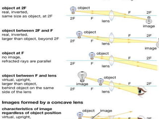
Image form by lens
• Unlike the mirrors, lenses have got two principal foci
one on each side of the lens and the nodal point is
situated within the substance of the lens just at the
centre. If the image is situated on the other side of the
object, it is called a Real Image and if it is on the
same side it is called a Virtual Image.
133.
May 29, 2025anjumk38dmc@gmail.com 133
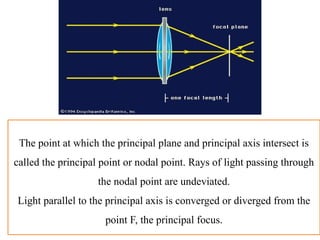
The point at which the principal plane and principal axis intersect is
called the principal point or nodal point. Rays of light passing through
the nodal point are undeviated.
Light parallel to the principal axis is converged or diverged from the
point F, the principal focus.
134.
May 29, 2025anjumk38dmc@gmail.com 134
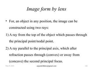
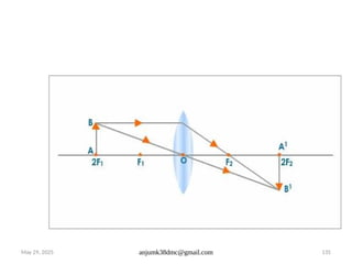
Image form by lens
• For, an object in any position, the image can be
constructed using two rays:
1) A ray from the top of the object which passes through
the principal point/nodal point.
2) A ray parallel to the principal axis, which after
refraction passes through (convex) or away from
(concave) the second principal focus.
May 29, 2025anjumk38dmc@gmail.com 136
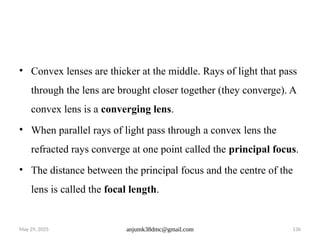
• Convex lenses are thicker at the middle. Rays of light that pass
through the lens are brought closer together (they converge). A
convex lens is a converging lens.
• When parallel rays of light pass through a convex lens the
refracted rays converge at one point called the principal focus.
• The distance between the principal focus and the centre of the
lens is called the focal length.
May 29, 2025anjumk38dmc@gmail.com 138
Use of Convex Lenses
Use of Convex Lenses – The Camera
A camera consists of three main parts.
I. The body which is light tight and contains all the mechanical
parts.
II. The lens which is a convex (converging) lens.
III. The film or a charged couple device in the case of a digital
camera.
May 29, 2025anjumk38dmc@gmail.com 140
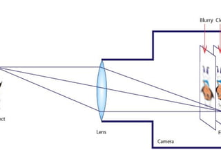
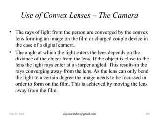
Use of Convex Lenses – The Camera
• The rays of light from the person are converged by the convex
lens forming an image on the film or charged couple device in
the case of a digital camera.
• The angle at which the light enters the lens depends on the
distance of the object from the lens. If the object is close to the
lens the light rays enter at a sharper angled. This results in the
rays converging away from the lens. As the lens can only bend
the light to a certain degree the image needs to be focussed in
order to form on the film. This is achieved by moving the lens
away from the film.
141.
May 29, 2025anjumk38dmc@gmail.com 141
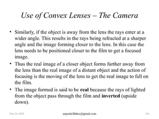
Use of Convex Lenses – The Camera
• Similarly, if the object is away from the lens the rays enter at a
wider angle. This results in the rays being refracted at a sharper
angle and the image forming closer to the lens. In this case the
lens needs to be positioned closer to the film to get a focused
image.
• Thus the real image of a closer object forms further away from
the lens than the real image of a distant object and the action of
focusing is the moving of the lens to get the real image to fall on
the film.
• The image formed is said to be real because the rays of lighted
from the object pass through the film and inverted (upside
down).
142.
May 29, 2025anjumk38dmc@gmail.com 142
The Magnifying Glass
A magnifying glass is a convex lens which produces a magnified
(larger) image of an object.
• A magnifying glass produces an upright, magnified virtual
image. The virtual image produced is on the same side of the
lens as the object. For a magnified image to be observed the
distance between the object and the lens must be shorter than
the focal length of the lens.
143.
May 29, 2025anjumk38dmc@gmail.com 143
For a magnified image to be observed the distance
between the object and the lens has to be shorter than
the focal length of the lens. The image formed is
upright, magnified and virtual.
144.
May 29, 2025anjumk38dmc@gmail.com 144
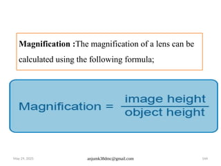
Magnification :The magnification of a lens can be
calculated using the following formula;
May 29, 2025anjumk38dmc@gmail.com 146
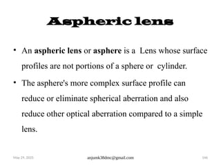
Aspheric lens
• An aspheric lens or asphere is a Lens whose surface
profiles are not portions of a sphere or cylinder.
• The asphere's more complex surface profile can
reduce or eliminate spherical aberration and also
reduce other optical aberration compared to a simple
lens.
May 29, 2025anjumk38dmc@gmail.com 148
Polarization
Since a light wave’s electric field vibrates in a
direction perpendicular to its propagation motion, it is
called a transverse wave and is polarizable.
A sound wave, by contrast, vibrates back and forth
along its propagation direction and thus is not
polarizable.
149.
May 29, 2025anjumk38dmc@gmail.com 149
What is Polarization?
Light waves are travelling may or may not be parallel
to each other. If directions are randomly related to
each other the light is UNPOLARIZED/ NONPOLARIZED.
If parallel to each other is called POLARIZED.
150.
May 29, 2025anjumk38dmc@gmail.com 150
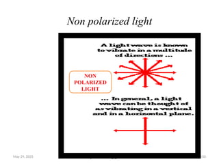
Non polarized light
NON
POLARIZED
LIGHT
151.
May 29, 2025anjumk38dmc@gmail.com 151
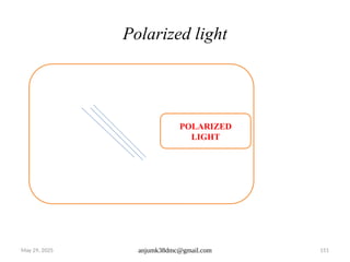
Polarized light
POLARIZED
LIGHT
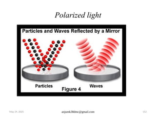
152.
May 29, 2025anjumk38dmc@gmail.com 152
Polarized light
153.
May 29, 2025anjumk38dmc@gmail.com 153
How light is polarized?
Polarized light is produced from ordinary light by an
encounter with a polarizing substances or agent.
Polarizing substances, e,g. calcite crystal, only
transmit light rays which are vibrating in one
particular plane. Thus only a proportion of incident
light is transmitted onward and the emerging light is
polarized.
154.
May 29, 2025anjumk38dmc@gmail.com 154
How light is polarized?
A polarizing medium reduces radiant intensity but
does not affect spectral composition.
In nature, light is polarized on reflection from a plane
surface. Such as water, if the angle of incidence is
equal to the polarizing angle for the substances. The
polarizing angle is dependent on the refractive index
of the substance.
155.
May 29, 2025anjumk38dmc@gmail.com 155
Application of polarized light
Polarized sunglasses to exclude selectively the
reflected horizontal polarized light. Such glasses are
of great use in reducing glare from the sea or wet
roads.
Instruments: (to reduced reflected glare from the
cornea) example: Slit lamp Ophthalmoscope
156.
May 29, 2025anjumk38dmc@gmail.com 156
Application of polarized light
Binocular vision polarizing glass – May be used to
dissociate the eyes i,e in Titmus test
Also used in pleoptic to produced Haidinger’s
brushes and in optical lens making to examine lens
for stress.
157.
May 29, 2025anjumk38dmc@gmail.com 157
Birefringence
Some substances have double refractive index though
they transmit light into 2 direction and they are called
Birefringence
A widely used birefringent material is Calcite Its
birefringence is extremely large, with indices of
refraction for the o- and e-rays of 1.6584 and 1.4864
respectively.
158.
May 29, 2025anjumk38dmc@gmail.com 158
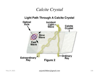
Calcite Crystal
159.
May 29, 2025anjumk38dmc@gmail.com 159
Applications of Birefringence
Birefringence finds use in the following applications:
Polarizing prisms and retarder plates
Liquid crystal displays
Medical Diagnostics
05/29/2025 anjumk38dmc@gmail.com 162
The maximum value of the wave displacement is
called the amplitude (A) of the wave.
The cycle starts at zero and repeats after a distance.
This distance is called the wavelength (λ).
Light can have different wavelengths. The inverse of
the wavelength (1/λ) is the wave number (ν), which
is expressed in cm–1.
163.
05/29/2025 anjumk38dmc@gmail.com 163
The wave propagates at a wave speed (v). This wave
speed in a vacuum is equal to c, and is less than c in a
medium.
At a stationary point along the wave, the wave passes
by in a repeating cycle. The time to complete one
cycle is called the cycle time or period
164.
05/29/2025 anjumk38dmc@gmail.com 164
Another important measure of a wave is its
frequency (f). It is measured as the number of
waves that pass a given point in one second. The unit
for frequency is cycles per second, also called hertz
(Hz).
165.
• As wecan see, the frequency and the period are
reciprocals of one another. If the wave speed and
wavelength are known, the frequency can be
calculated.
166.
05/29/2025 anjumk38dmc@gmail.com 166
Wavelike model of Light
• The particle-like model of light describes large-scale effects
such as light passing through lenses or bouncing off mirrors.
• However, a wavelike model must be used to describe fine-
scale effects such as interference and diffraction that occur
when light passes through small openings or by sharp edges.
• The propagation of light or electromagnetic energy through
space can be described in terms of a traveling wave motion.
167.
05/29/2025 anjumk38dmc@gmail.com 167
Thewave moves energy—without moving mass—from one place
to another at a speed independent of its intensity or wavelength.
This wave nature of light is the basis of physical optics and
describes the interaction of light with media. Many of these
processes require calculus and quantum theory to describe them
rigorously.
168.
05/29/2025 anjumk38dmc@gmail.com 168
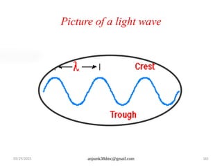
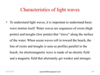
Characteristicsof light waves
• To understand light waves, it is important to understand basic
wave motion itself. Water waves are sequences of crests (high
points) and troughs (low points) that “move” along the surface
of the water. When ocean waves roll in toward the beach, the
line of crests and troughs is seen as profiles parallel to the
beach. An electromagnetic wave is made of an electric field
and a magnetic field that alternately get weaker and stronger.
169.
05/29/2025 anjumk38dmc@gmail.com 169
Characteristicsof light waves
• The directions of the fields are at right angles to the direction
the wave is moving, just as the motion of the water is up and
down while a water wave moves horizontally.
170.
May 29, 2025anjumk38dmc@gmail.com 170
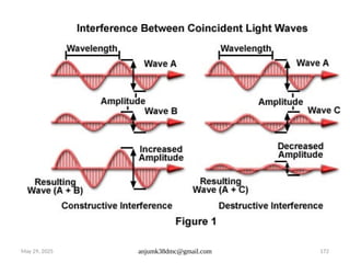
2. Interference
• When two light waves from different coherent
sources meet together, then the distribution of energy
due to one wave is disturbed by the other. This
modification in the distribution of light energy due to
super- position of two light waves is called
"Interference of light"
171.
May 29, 2025anjumk38dmc@gmail.com 171
Conditions for Interference
The two sources of light should emit continuous
waves of same wavelength and same time period i.e.
the source should have phase coherence.
The two sources of light should be very close to each
other. The waves emitted by two sources should
either have zero phase difference or no phase
difference.
May 29, 2025anjumk38dmc@gmail.com 173
Coherent sources
Those sources of light which emit light waves continuously of
same wavelength, and time period, frequency and
amplitude and have zero phase difference or constant phase
difference are coherent sources.
174.
May 29, 2025anjumk38dmc@gmail.com 174
Types of interference
There are two types of interference.
1) Constructive interference.
2) Destructive interference
175.
May 29, 2025anjumk38dmc@gmail.com 175
Interference
constructive interference destructive interference
176.
May 29, 2025anjumk38dmc@gmail.com 176
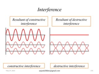
Interference
Resultant of constructive
interference
Resultant of destructive
interference
constructive interference destructive interference
177.
May 29, 2025anjumk38dmc@gmail.com 177
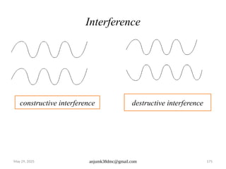
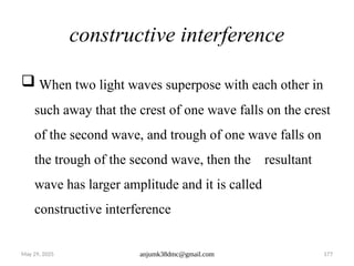
constructive interference
When two light waves superpose with each other in
such away that the crest of one wave falls on the crest
of the second wave, and trough of one wave falls on
the trough of the second wave, then the resultant
wave has larger amplitude and it is called
constructive interference
178.
May 29, 2025anjumk38dmc@gmail.com 178
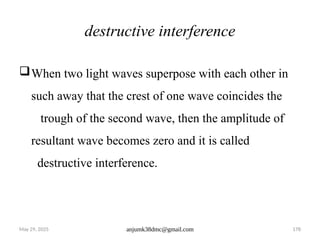
destructive interference
When two light waves superpose with each other in
such away that the crest of one wave coincides the
trough of the second wave, then the amplitude of
resultant wave becomes zero and it is called
destructive interference.
179.
May 29, 2025anjumk38dmc@gmail.com 179
Diffraction
The term diffraction, from the Latin diffringere, 'to
break into pieces', referring to light breaking up
180.
May 29, 2025anjumk38dmc@gmail.com 180
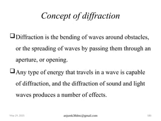
Concept of diffraction
Diffraction is the bending of waves around obstacles,
or the spreading of waves by passing them through an
aperture, or opening.
Any type of energy that travels in a wave is capable
of diffraction, and the diffraction of sound and light
waves produces a number of effects.
181.
May 29, 2025anjumk38dmc@gmail.com 181
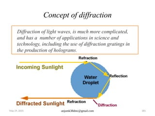
Concept of diffraction
Diffraction of light waves, is much more complicated,
and has a number of applications in science and
technology, including the use of diffraction gratings in
the production of holograms.
182.
May 29, 2025anjumk38dmc@gmail.com 182
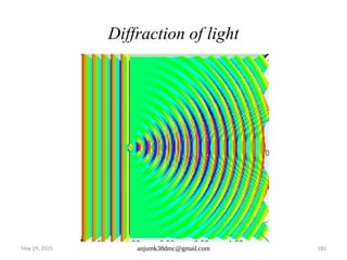
Diffraction of light
183.
May 29, 2025anjumk38dmc@gmail.com 183
Observing Diffraction in Light
• Wavelength of light plays a role in diffraction; so,
too, does the size of the aperture relative to the
wavelength. Hence, most studies of diffraction in
light involve very small openings, as, for instance, in
the diffraction grating.
• But light does not only diffract when passing through
an aperture, it also diffracts around obstacles.
184.
May 29, 2025anjumk38dmc@gmail.com 184
Observing Diffraction in Light
• When light passes through an aperture, most of the
beam goes straight through without disturbance, with
only the edges experiencing diffraction. If, however,
the size of the aperture is close to that of the
wavelength, the diffraction pattern will widen. when
light is passed through extremely narrow openings,
its diffraction is more noticeable.
185.
May 29, 2025anjumk38dmc@gmail.com 185
Diffraction Grating
• A diffraction grating is an optical device that consists of not
one but many thousands of apertures: Rowland's machine used
a fine diamond point to rule glass gratings, with about 15,000
lines per in (2.2 cm). Diffraction gratings today can have as
many as 100,000 apertures per inch.
186.
• The aperturesin a diffraction grating are not mere
holes, but extremely narrow parallel slits that transform
a beam of light into a spectrum.
• Each of these openings diffracts the light beam, but
because they are evenly spaced and the same in width,
the diffracted waves experience constructive
interference.
187.
May 29, 2025anjumk38dmc@gmail.com 187
• This constructive interference pattern makes it
possible to view components of the spectrum
separately, thus enabling a scientist to observe
characteristics ranging from the structure of atoms
and molecules to the chemical composition of stars.
188.
May 29, 2025anjumk38dmc@gmail.com 188
• You may also notice that the light is alternately bright
and dark as you look through the curtain. This is
from interference. The bright places are where light
waves are adding together. The dark places are where
the waves cancel. With visible light, interference
always occurs with diffraction.
#111 Snell’s Law: state that the incidence ray, refracted ray and the normal all lie in the same plane and that the angles of incidence, I, and refraction, r, are related to the refractive index, n, of the media concerned by the equation sin i/sin r