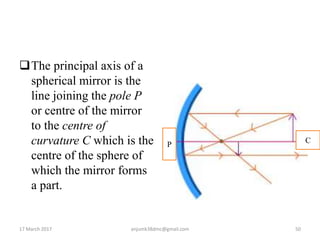
1) The document discusses key concepts in optics, including geometrical optics, physical optics, and quantum optics.
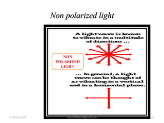
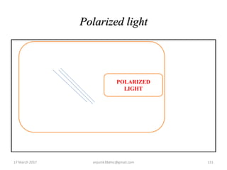
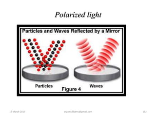
2) Geometrical optics deals with light rays and concepts like reflection and refraction. Physical optics examines light as waves and phenomena like interference and diffraction. Quantum optics views light as particles.
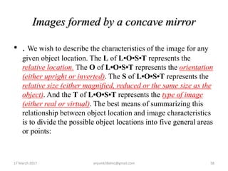
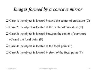
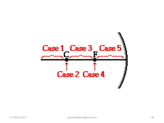
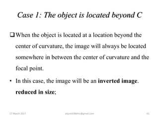
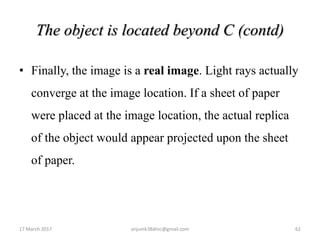
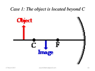
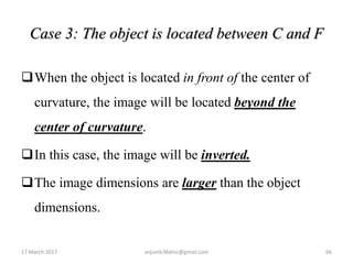
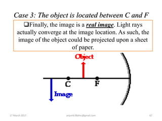
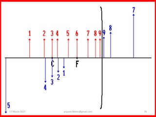
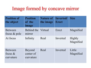
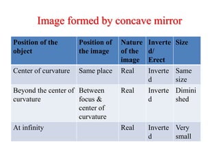
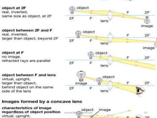
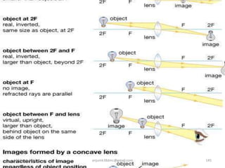
3) Images formed by concave mirrors depend on the object's location relative to the mirror's center of curvature and focal point. If beyond the center, the image is real, inverted, and smaller.