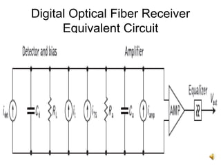
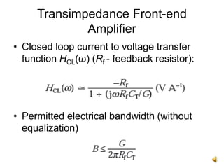
SlideShare a Scribd company logo
1 of 22
Optical Receivers
MEC
Contents
• Digital Optical Fiber Receiver.
• Equalizer.
• Amplifier Configurations
- Low-impedance Front-end.
- High-impedance Front-end.
- Transimpedance Front-end.
• Comparison
Digital Optical Fiber Receiver
• Optical detector represented as a current
source idet.
• Noise sources - it, iTS and iamp , amplifier
and equalizer follows.
• Equalization compensates for signal
distortion due to combined transmitter,
medium and receiver characteristics.
Digital Optical Fiber Receiver
Equivalent Circuit
Equalizer
• Equalizer a frequency-shaping filter,
frequency response inverse of overall
system frequency response.
• Boost high-frequency components, correct
overall amplitude of frequency response.
• To acquire desired spectral shape & to
minimize intersymbol interference, system
phase frequency response to be linear.
Equalizer
• Applies selective
phase shifts to
particular frequency
components.
• Minimize noise
contributions from the
sources, maximize
receiver sensitivity,
maintain a suitable
bandwidth.
Amplifier Configurations
• Basic amplifier
configurations:
- Low-impedance
front-end.
- High-impedance
(integrating) front-
end.
- Transimpedance
front-end.
Low-impedance Front-end Amplifier
• Voltage amplifier
with effective input
resistance Ra.
• Detector loaded with
a bias resistor Rb
and an amplifier.
• Bandwidth
determined by
passive impedance
across detector
terminals (RL).
Modified total load
resistance
Low-impedance Front-end Amplifier
• RL may be modified to incorporate the
parallel resistance of detector bias
resistor Rb and amplifier input resistance
Ra.
• To achieve optimum bandwidth, Rb and Ra
to be minimized - low-impedance front-end
design.
• Design allows thermal noise to dominate
within the receiver, limits sensitivity.
Low-impedance Front-end Amplifier
• Trade-off between bandwidth and
sensitivity.
• Impractical for long-haul, wideband optical
fiber communication systems.
High-impedance (integrating)
Front-end Amplifier
• High i/p impedance
amplifier together
with a large detector
bias resistor to
reduce the effect of
thermal noise.
• Degraded frequency
response, bandwidth
relationship not
maintained for
wideband operation.
High-impedance (integrating)
Front-end Amplifier
• Detector output effectively integrated over
a large time constant, must be restored by
differentiation.
• Correct equalization required.
• Improvement in sensitivity over low-
impedance front-end design, creates a
heavy demand for equalization, limited
dynamic range.
High-impedance (integrating)
Front-end Amplifier
• Limitations on dynamic range result from
attenuation of the low-frequency signal
components by equalization, causes
amplifier to saturate at high signal levels.
• Amplifier saturates before equalization,
signal is heavily distorted.
• Reduction in dynamic range depends on
the amount of integration and subsequent
equalization employed.
Transimpedance Front-end
Amplifier
• Overcomes drawbacks of high-impedance
front end.
• Low-noise, high-input-impedance amplifier
with negative feedback.
• Operates as current mode amplifier, high
input impedance reduced by negative
feedback.
Transimpedance Front-end
Amplifier
Transimpedance Front-end
Amplifier
• Open loop current to voltage transfer
function HOL (ω)
G - open loop voltage gain of the
amplifier, ω - angular frequency of input.
Transimpedance Front-end
Amplifier
• Closed loop current to voltage transfer
function HCL(ω) (Rf - feedback resistor):
• Permitted electrical bandwidth (without
equalization)
Transimpedance Front-end
Amplifier
• Greater bandwidth than amplifiers without
feedback.
• When Rf << RTL, major noise contribution
is from thermal noise generated in Rf.
• Noise performance improved when Rf is
large.
• When Rf = RTL, noise performance
approaches that of high-impedance front
end.
Transimpedance Front-end
Amplifier
• Rf cannot be increased indefinitely due to
problems of stability with closed loop
design.
• Increasing Rf reduces bandwidth.
• Make G as large as the stability of closed
loop permits.
• Noise in transimpedance amplifier exceed
that incurred by high-impedance front-end
structure.
Transimpedance Front-end
Amplifier
• Greater bandwidth without equalization
than high-impedance front-end, but offset
by 13 dB noise penalty incurred.
• Optimized for noise performance at the
expense of bandwidth.
• Improvement in noise performance over
low-impedance front-end structures.
• Greater dynamic range.
Transimpedance Front-end
Amplifier
• Different attenuation mechanism for low
frequency components of the signal.
• Attenuation through negative feedback, low
frequency components amplified by device
closed loop rather than open loop gain.
• Improvement in dynamic range equal to
ratio of open loop to closed loop gains.
• Used in wideband optical fiber
communication receivers.
Thank You

More Related Content

What's hot

Optical amplifier
Optical amplifierOptical amplifier
Optical amplifier
chnru
 
Audio power amplifier
Audio power amplifierAudio power amplifier
Audio power amplifier
Andri Haryono
 
LNA Presentation to Ciena
LNA Presentation to CienaLNA Presentation to Ciena
LNA Presentation to Ciena
Paul Mushubi
 
AM RadioReceiver
AM RadioReceiverAM RadioReceiver
AM RadioReceiver
Prachi Dave
 
Pre amplifier desiging for phsiological
Pre amplifier desiging for phsiologicalPre amplifier desiging for phsiological
Pre amplifier desiging for phsiological
Surendra Meena
 

What's hot (19)

Electronic instrumentation in NMT
Electronic instrumentation in NMTElectronic instrumentation in NMT
Electronic instrumentation in NMT
 
Basics of amplifier
Basics of amplifierBasics of amplifier
Basics of amplifier
 
Optical amplifier
Optical amplifierOptical amplifier
Optical amplifier
 
Audio power amplifier
Audio power amplifierAudio power amplifier
Audio power amplifier
 
Vivek
VivekVivek
Vivek
 
Ut installation review
Ut installation reviewUt installation review
Ut installation review
 
Receivers
ReceiversReceivers
Receivers
 
Receivers
ReceiversReceivers
Receivers
 
Radio Frequency and Intermediate Frequency Amplifiers
Radio Frequency and Intermediate Frequency AmplifiersRadio Frequency and Intermediate Frequency Amplifiers
Radio Frequency and Intermediate Frequency Amplifiers
 
Qualprez
QualprezQualprez
Qualprez
 
LNA Presentation to Ciena
LNA Presentation to CienaLNA Presentation to Ciena
LNA Presentation to Ciena
 
AM RadioReceiver
AM RadioReceiverAM RadioReceiver
AM RadioReceiver
 
Oscilloscope Lab
Oscilloscope LabOscilloscope Lab
Oscilloscope Lab
 
OP AMP Applications
OP AMP ApplicationsOP AMP Applications
OP AMP Applications
 
Pre amplifier desiging for phsiological
Pre amplifier desiging for phsiologicalPre amplifier desiging for phsiological
Pre amplifier desiging for phsiological
 
LASER DRIVER FOR HIGH POWER ERBIUM DOPED FIBER AMPLIFIER (EDFA)
LASER DRIVER FOR HIGH POWER ERBIUM DOPED FIBER AMPLIFIER (EDFA)LASER DRIVER FOR HIGH POWER ERBIUM DOPED FIBER AMPLIFIER (EDFA)
LASER DRIVER FOR HIGH POWER ERBIUM DOPED FIBER AMPLIFIER (EDFA)
 
Emi unit iii ppt
Emi unit iii pptEmi unit iii ppt
Emi unit iii ppt
 
Data acquisition and conversion
Data acquisition and conversionData acquisition and conversion
Data acquisition and conversion
 
lab_13_14_essay
lab_13_14_essaylab_13_14_essay
lab_13_14_essay
 

Similar to Optical receivers

FM demodu super hetero.pptx
FM demodu super hetero.pptxFM demodu super hetero.pptx
FM demodu super hetero.pptx
saima87
 
Aeav 311 lecture 25 26- inst.amp+noise
Aeav 311 lecture 25 26- inst.amp+noiseAeav 311 lecture 25 26- inst.amp+noise
Aeav 311 lecture 25 26- inst.amp+noise
0mehdi
 

Similar to Optical receivers (20)

Optical amplification
Optical amplificationOptical amplification
Optical amplification
 
Optical amplifiers
Optical amplifiersOptical amplifiers
Optical amplifiers
 
FM demodu super hetero.pptx
FM demodu super hetero.pptxFM demodu super hetero.pptx
FM demodu super hetero.pptx
 
Radio Recivers slides.pdf
Radio Recivers slides.pdfRadio Recivers slides.pdf
Radio Recivers slides.pdf
 
Low Pass Filter - Classification
Low Pass Filter - ClassificationLow Pass Filter - Classification
Low Pass Filter - Classification
 
Amplifier.pptx
Amplifier.pptxAmplifier.pptx
Amplifier.pptx
 
EC2-NOTES-PPT.ppt
EC2-NOTES-PPT.pptEC2-NOTES-PPT.ppt
EC2-NOTES-PPT.ppt
 
Op-Amp Basics Part I
Op-Amp Basics Part IOp-Amp Basics Part I
Op-Amp Basics Part I
 
A Class-C Power Amplifiers Type of Tuned Amplifiers
A Class-C Power Amplifiers Type of Tuned AmplifiersA Class-C Power Amplifiers Type of Tuned Amplifiers
A Class-C Power Amplifiers Type of Tuned Amplifiers
 
AMPLIFIERS.pptx
AMPLIFIERS.pptxAMPLIFIERS.pptx
AMPLIFIERS.pptx
 
2. Communication System.pptx
2. Communication System.pptx2. Communication System.pptx
2. Communication System.pptx
 
Optical amplifiers- review
Optical amplifiers- reviewOptical amplifiers- review
Optical amplifiers- review
 
Aeav 311 lecture 25 26- inst.amp+noise
Aeav 311 lecture 25 26- inst.amp+noiseAeav 311 lecture 25 26- inst.amp+noise
Aeav 311 lecture 25 26- inst.amp+noise
 
Radio Communications.pdf
Radio Communications.pdfRadio Communications.pdf
Radio Communications.pdf
 
Semiconductor optical amplifiers
Semiconductor optical amplifiersSemiconductor optical amplifiers
Semiconductor optical amplifiers
 
Integrated circuits
Integrated circuitsIntegrated circuits
Integrated circuits
 
UNIT-4.pptx
UNIT-4.pptxUNIT-4.pptx
UNIT-4.pptx
 
311 angle modulation
311 angle modulation311 angle modulation
311 angle modulation
 
RADIO RECEIVER STAGES.pptx
RADIO RECEIVER STAGES.pptxRADIO RECEIVER STAGES.pptx
RADIO RECEIVER STAGES.pptx
 
RECEIVERS.ppt
RECEIVERS.pptRECEIVERS.ppt
RECEIVERS.ppt
 

More from CKSunith1

More from CKSunith1 (20)

EST 130, Modulation
EST 130, ModulationEST 130, Modulation
EST 130, Modulation
 
EST 130, Transistor Biasing and Amplification.
EST 130, Transistor Biasing and Amplification.EST 130, Transistor Biasing and Amplification.
EST 130, Transistor Biasing and Amplification.
 
EST 200, Design Thinking in Automobile Industry
EST 200, Design Thinking in Automobile IndustryEST 200, Design Thinking in Automobile Industry
EST 200, Design Thinking in Automobile Industry
 
EST 130, Bipolar Junction Transistors
EST 130, Bipolar Junction TransistorsEST 130, Bipolar Junction Transistors
EST 130, Bipolar Junction Transistors
 
CSL 202, Shift Registers using Flipflops
CSL 202, Shift Registers using FlipflopsCSL 202, Shift Registers using Flipflops
CSL 202, Shift Registers using Flipflops
 
EST 130, PN Junction Diodes
EST 130, PN Junction DiodesEST 130, PN Junction Diodes
EST 130, PN Junction Diodes
 
EST 200, Oral and Written Communications
EST 200, Oral and Written CommunicationsEST 200, Oral and Written Communications
EST 200, Oral and Written Communications
 
CSL 202, Counters using Flipflops
CSL 202, Counters using FlipflopsCSL 202, Counters using Flipflops
CSL 202, Counters using Flipflops
 
EST 200, Designing Triggers for Behavior Change
EST 200, Designing Triggers for Behavior ChangeEST 200, Designing Triggers for Behavior Change
EST 200, Designing Triggers for Behavior Change
 
EST 200, Communicating Designs Graphically
EST 200, Communicating Designs GraphicallyEST 200, Communicating Designs Graphically
EST 200, Communicating Designs Graphically
 
EST 130, Semiconductors
EST 130, SemiconductorsEST 130, Semiconductors
EST 130, Semiconductors
 
EST 200, Design Thinking in Teams
EST 200, Design Thinking in TeamsEST 200, Design Thinking in Teams
EST 200, Design Thinking in Teams
 
EST 200, Design Thinking in a Work Place.
EST 200, Design Thinking in a Work Place.EST 200, Design Thinking in a Work Place.
EST 200, Design Thinking in a Work Place.
 
CSL 202, Flipflops using Logic Gates
CSL 202, Flipflops using Logic GatesCSL 202, Flipflops using Logic Gates
CSL 202, Flipflops using Logic Gates
 
EST 200, Convergent and Divergent Thinking
EST 200, Convergent and Divergent ThinkingEST 200, Convergent and Divergent Thinking
EST 200, Convergent and Divergent Thinking
 
EST 200, Design Thinking in a Work Place
EST 200, Design Thinking in a Work PlaceEST 200, Design Thinking in a Work Place
EST 200, Design Thinking in a Work Place
 
EST 200, Design Thinking
EST 200, Design ThinkingEST 200, Design Thinking
EST 200, Design Thinking
 
EST 130, Identifying Active Components
EST 130, Identifying Active ComponentsEST 130, Identifying Active Components
EST 130, Identifying Active Components
 
CSL 202, Multiplexer and Demultiplexer
CSL 202, Multiplexer and DemultiplexerCSL 202, Multiplexer and Demultiplexer
CSL 202, Multiplexer and Demultiplexer
 
Est 130 passive components inductors
Est 130 passive components inductorsEst 130 passive components inductors
Est 130 passive components inductors
 

Recently uploaded

CNv6 Instructor Chapter 6 Quality of Service
CNv6 Instructor Chapter 6 Quality of ServiceCNv6 Instructor Chapter 6 Quality of Service
CNv6 Instructor Chapter 6 Quality of Service
giselly40
 
Artificial Intelligence: Facts and Myths
Artificial Intelligence: Facts and MythsArtificial Intelligence: Facts and Myths
Artificial Intelligence: Facts and Myths
Joaquim Jorge
 

Recently uploaded (20)

Exploring the Future Potential of AI-Enabled Smartphone Processors
Exploring the Future Potential of AI-Enabled Smartphone ProcessorsExploring the Future Potential of AI-Enabled Smartphone Processors
Exploring the Future Potential of AI-Enabled Smartphone Processors
 
Automating Google Workspace (GWS) & more with Apps Script
Automating Google Workspace (GWS) & more with Apps ScriptAutomating Google Workspace (GWS) & more with Apps Script
Automating Google Workspace (GWS) & more with Apps Script
 
The Codex of Business Writing Software for Real-World Solutions 2.pptx
The Codex of Business Writing Software for Real-World Solutions 2.pptxThe Codex of Business Writing Software for Real-World Solutions 2.pptx
The Codex of Business Writing Software for Real-World Solutions 2.pptx
 
Breaking the Kubernetes Kill Chain: Host Path Mount
Breaking the Kubernetes Kill Chain: Host Path MountBreaking the Kubernetes Kill Chain: Host Path Mount
Breaking the Kubernetes Kill Chain: Host Path Mount
 
Data Cloud, More than a CDP by Matt Robison
Data Cloud, More than a CDP by Matt RobisonData Cloud, More than a CDP by Matt Robison
Data Cloud, More than a CDP by Matt Robison
 
GenCyber Cyber Security Day Presentation
GenCyber Cyber Security Day PresentationGenCyber Cyber Security Day Presentation
GenCyber Cyber Security Day Presentation
 
CNv6 Instructor Chapter 6 Quality of Service
CNv6 Instructor Chapter 6 Quality of ServiceCNv6 Instructor Chapter 6 Quality of Service
CNv6 Instructor Chapter 6 Quality of Service
 
Artificial Intelligence: Facts and Myths
Artificial Intelligence: Facts and MythsArtificial Intelligence: Facts and Myths
Artificial Intelligence: Facts and Myths
 
Real Time Object Detection Using Open CV
Real Time Object Detection Using Open CVReal Time Object Detection Using Open CV
Real Time Object Detection Using Open CV
 
Apidays Singapore 2024 - Building Digital Trust in a Digital Economy by Veron...
Apidays Singapore 2024 - Building Digital Trust in a Digital Economy by Veron...Apidays Singapore 2024 - Building Digital Trust in a Digital Economy by Veron...
Apidays Singapore 2024 - Building Digital Trust in a Digital Economy by Veron...
 
How to Troubleshoot Apps for the Modern Connected Worker
How to Troubleshoot Apps for the Modern Connected WorkerHow to Troubleshoot Apps for the Modern Connected Worker
How to Troubleshoot Apps for the Modern Connected Worker
 
Boost PC performance: How more available memory can improve productivity
Boost PC performance: How more available memory can improve productivityBoost PC performance: How more available memory can improve productivity
Boost PC performance: How more available memory can improve productivity
 
08448380779 Call Girls In Civil Lines Women Seeking Men
08448380779 Call Girls In Civil Lines Women Seeking Men08448380779 Call Girls In Civil Lines Women Seeking Men
08448380779 Call Girls In Civil Lines Women Seeking Men
 
Strategies for Unlocking Knowledge Management in Microsoft 365 in the Copilot...
Strategies for Unlocking Knowledge Management in Microsoft 365 in the Copilot...Strategies for Unlocking Knowledge Management in Microsoft 365 in the Copilot...
Strategies for Unlocking Knowledge Management in Microsoft 365 in the Copilot...
 
08448380779 Call Girls In Friends Colony Women Seeking Men
08448380779 Call Girls In Friends Colony Women Seeking Men08448380779 Call Girls In Friends Colony Women Seeking Men
08448380779 Call Girls In Friends Colony Women Seeking Men
 
Raspberry Pi 5: Challenges and Solutions in Bringing up an OpenGL/Vulkan Driv...
Raspberry Pi 5: Challenges and Solutions in Bringing up an OpenGL/Vulkan Driv...Raspberry Pi 5: Challenges and Solutions in Bringing up an OpenGL/Vulkan Driv...
Raspberry Pi 5: Challenges and Solutions in Bringing up an OpenGL/Vulkan Driv...
 
A Call to Action for Generative AI in 2024
A Call to Action for Generative AI in 2024A Call to Action for Generative AI in 2024
A Call to Action for Generative AI in 2024
 
Axa Assurance Maroc - Insurer Innovation Award 2024
Axa Assurance Maroc - Insurer Innovation Award 2024Axa Assurance Maroc - Insurer Innovation Award 2024
Axa Assurance Maroc - Insurer Innovation Award 2024
 
Advantages of Hiring UIUX Design Service Providers for Your Business
Advantages of Hiring UIUX Design Service Providers for Your BusinessAdvantages of Hiring UIUX Design Service Providers for Your Business
Advantages of Hiring UIUX Design Service Providers for Your Business
 
08448380779 Call Girls In Diplomatic Enclave Women Seeking Men
08448380779 Call Girls In Diplomatic Enclave Women Seeking Men08448380779 Call Girls In Diplomatic Enclave Women Seeking Men
08448380779 Call Girls In Diplomatic Enclave Women Seeking Men
 

Optical receivers

  • 2. Contents • Digital Optical Fiber Receiver. • Equalizer. • Amplifier Configurations - Low-impedance Front-end. - High-impedance Front-end. - Transimpedance Front-end. • Comparison
  • 3. Digital Optical Fiber Receiver • Optical detector represented as a current source idet. • Noise sources - it, iTS and iamp , amplifier and equalizer follows. • Equalization compensates for signal distortion due to combined transmitter, medium and receiver characteristics.
  • 4. Digital Optical Fiber Receiver Equivalent Circuit
  • 5. Equalizer • Equalizer a frequency-shaping filter, frequency response inverse of overall system frequency response. • Boost high-frequency components, correct overall amplitude of frequency response. • To acquire desired spectral shape & to minimize intersymbol interference, system phase frequency response to be linear.
  • 6. Equalizer • Applies selective phase shifts to particular frequency components. • Minimize noise contributions from the sources, maximize receiver sensitivity, maintain a suitable bandwidth.
  • 7. Amplifier Configurations • Basic amplifier configurations: - Low-impedance front-end. - High-impedance (integrating) front- end. - Transimpedance front-end.
  • 8. Low-impedance Front-end Amplifier • Voltage amplifier with effective input resistance Ra. • Detector loaded with a bias resistor Rb and an amplifier. • Bandwidth determined by passive impedance across detector terminals (RL). Modified total load resistance
  • 9. Low-impedance Front-end Amplifier • RL may be modified to incorporate the parallel resistance of detector bias resistor Rb and amplifier input resistance Ra. • To achieve optimum bandwidth, Rb and Ra to be minimized - low-impedance front-end design. • Design allows thermal noise to dominate within the receiver, limits sensitivity.
  • 10. Low-impedance Front-end Amplifier • Trade-off between bandwidth and sensitivity. • Impractical for long-haul, wideband optical fiber communication systems.
  • 11. High-impedance (integrating) Front-end Amplifier • High i/p impedance amplifier together with a large detector bias resistor to reduce the effect of thermal noise. • Degraded frequency response, bandwidth relationship not maintained for wideband operation.
  • 12. High-impedance (integrating) Front-end Amplifier • Detector output effectively integrated over a large time constant, must be restored by differentiation. • Correct equalization required. • Improvement in sensitivity over low- impedance front-end design, creates a heavy demand for equalization, limited dynamic range.
  • 13. High-impedance (integrating) Front-end Amplifier • Limitations on dynamic range result from attenuation of the low-frequency signal components by equalization, causes amplifier to saturate at high signal levels. • Amplifier saturates before equalization, signal is heavily distorted. • Reduction in dynamic range depends on the amount of integration and subsequent equalization employed.
  • 14. Transimpedance Front-end Amplifier • Overcomes drawbacks of high-impedance front end. • Low-noise, high-input-impedance amplifier with negative feedback. • Operates as current mode amplifier, high input impedance reduced by negative feedback.
  • 16. Transimpedance Front-end Amplifier • Open loop current to voltage transfer function HOL (ω) G - open loop voltage gain of the amplifier, ω - angular frequency of input.
  • 17. Transimpedance Front-end Amplifier • Closed loop current to voltage transfer function HCL(ω) (Rf - feedback resistor): • Permitted electrical bandwidth (without equalization)
  • 18. Transimpedance Front-end Amplifier • Greater bandwidth than amplifiers without feedback. • When Rf << RTL, major noise contribution is from thermal noise generated in Rf. • Noise performance improved when Rf is large. • When Rf = RTL, noise performance approaches that of high-impedance front end.
  • 19. Transimpedance Front-end Amplifier • Rf cannot be increased indefinitely due to problems of stability with closed loop design. • Increasing Rf reduces bandwidth. • Make G as large as the stability of closed loop permits. • Noise in transimpedance amplifier exceed that incurred by high-impedance front-end structure.
  • 20. Transimpedance Front-end Amplifier • Greater bandwidth without equalization than high-impedance front-end, but offset by 13 dB noise penalty incurred. • Optimized for noise performance at the expense of bandwidth. • Improvement in noise performance over low-impedance front-end structures. • Greater dynamic range.
  • 21. Transimpedance Front-end Amplifier • Different attenuation mechanism for low frequency components of the signal. • Attenuation through negative feedback, low frequency components amplified by device closed loop rather than open loop gain. • Improvement in dynamic range equal to ratio of open loop to closed loop gains. • Used in wideband optical fiber communication receivers.