Download as PDF, PPTX


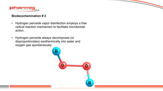
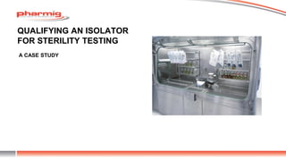


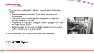
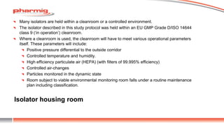


The document discusses sterility testing isolators, focusing on their design, operation, and maintenance to minimize contamination risks during testing. Key aspects include validating decontamination cycles with biological indicators, managing airflow and pressure, and regular sanitization procedures. A case study highlights operational criteria and the importance of tracking parameters like gas concentration and environmental monitoring to ensure effective sterility testing.


![stirlization - Copy [Recovered].ppsx](https://cdn.slidesharecdn.com/ss_thumbnails/stirlization-copyrecovered-221212090857-e0153d3b-thumbnail.jpg?width=640&height=640&fit=bounds)


