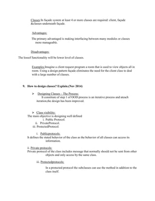
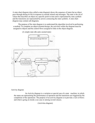
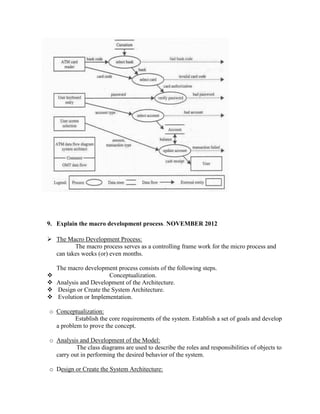
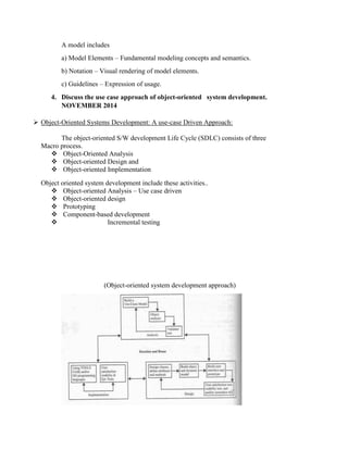
This document contains definitions and explanations of object-oriented analysis and design concepts. It begins with definitions of polymorphism, the micro development process, object-oriented analysis and design, and the Unified Modeling Language (UML). It then discusses pattern templates, the need for a unified modeling approach, reasons for object orientation, the power of prototypes, multiple inheritance, and the goal of object-oriented design. The remaining sections provide more details on specific concepts like relationships, associations, frameworks, methodologies like Booch and design patterns.

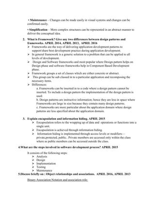
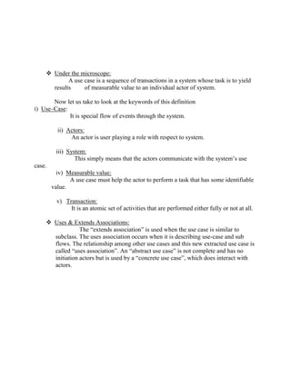
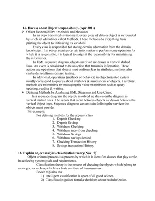
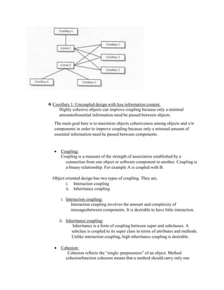
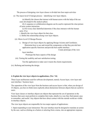
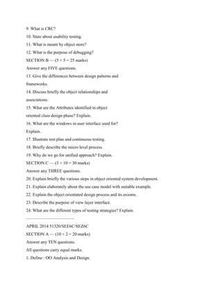
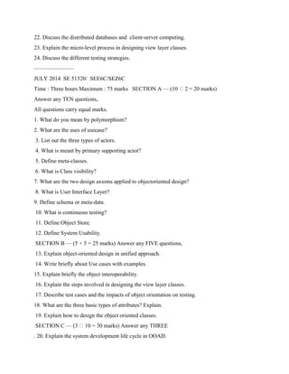
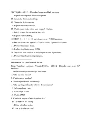
![6. Discuss the design patterns.NOVEMBER 2014
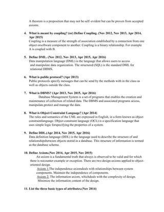
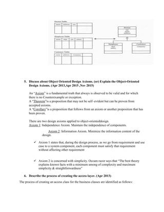
Design pattern is instructive information for that captures the essential structure and
insight of a successful family of proven design solutions to a recurring problem that
arises within a certain context.
Gang of Four (GoF) [Erich Gamma, Richard Helm, Ralph Johnson and John Vlissides]
introduced the concept of design patterns.
Characteristics of Design Patterns:
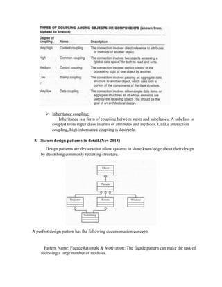
1. It solves the problem – Design patterns are not just abstract representations of
theoretical research. To be accepted as a pattern it should have some proves practical
experiences.
2. It’s a proven concept – Patterns must have a successful history.
3. It describes a relationship – Patterns do not specify a single class instead it specifies
more than one classes and their relationship.
4. It has a human component - Good patterns make the job of the programmer easy and
time saving.
Contents of Design Pattern:
• Name of the pattern is used to identify the pattern as well as an descriptive of the
problem solution in general. Easy to remember and context related names makes
remembering patterns easy.
• Context of the pattern describes when and where the pattern is applicable. It also
describes the purpose of pattern and also the place where it is not applicable due to some
specific conditions.
• Solution of the design pattern is describes how to build the appropriate design using this
appropriate design.
• Consequences of design patterns describe the impact of choosing a particular design
pattern in a system.
Pattern templates: There are different pattern templates are available which will represent
a pattern. It is generally agreed that a pattern should contain certain following
components.
Name : A meaningful name.
Problem : A statement of the problem that describes its intent.
Context : The preconditions under which the problem and its solution seem to recur and
for which the solution is desirable. This tells us the pattern’s applicability.
Forces : constraints and conflicts with one another with the goals which we wish to
achieve.
Solution : solution makes the pattern come alive.
Examples : sample implementation
Resulting context : describes the post conditions and side effects of the pattern.
Rationale : justifying explanation of steps or rules in the pattern. This tells how the
pattern actually works, why it works and why it is good.
Related patterns. : The static and dynamic relationships between these patterns and others
with in the same pattern language or system.](https://image.slidesharecdn.com/ooad-full-units1-220928071300-d5a3b37f/85/OOAD-FULL-UNITS-full-unit-SEE6A-10-320.jpg)
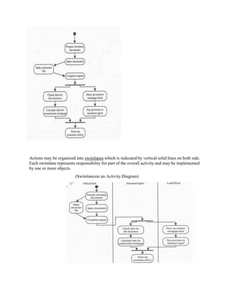
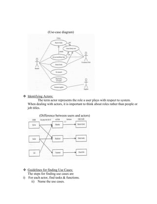
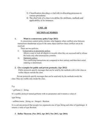
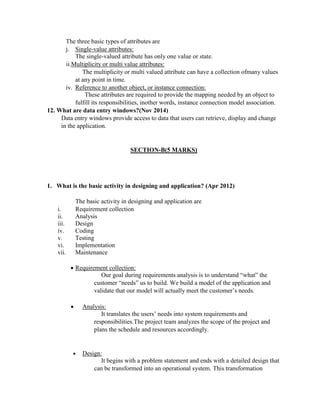
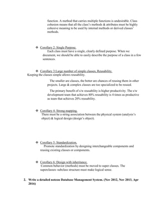
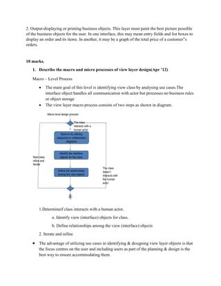
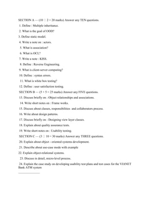
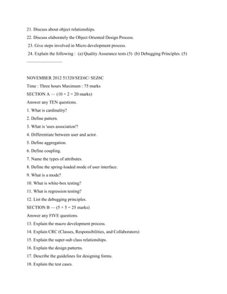
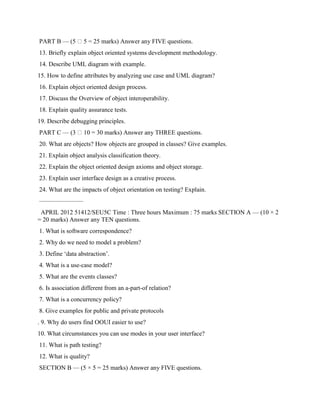
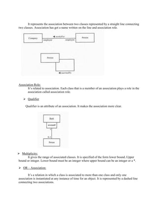
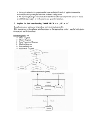
![7. Explain the system development life cycle in OOAD. JULY 2014,APRIL 2013,
APRIL 2016
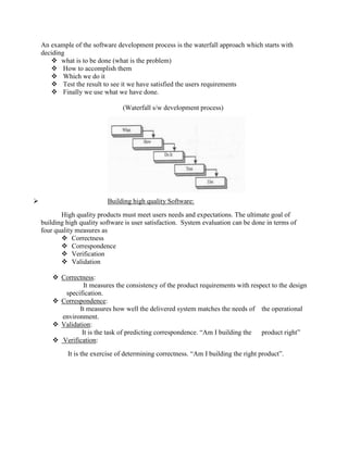
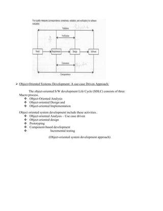
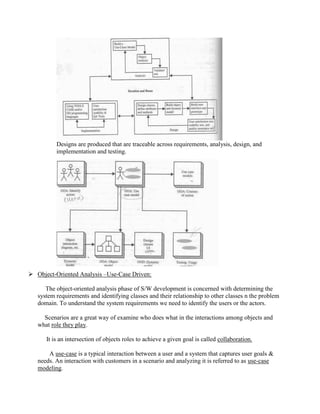
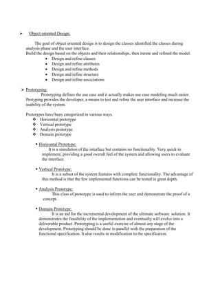
Software Development process:
A process can be divided into small interacting phases sub process.
Each sub process mush have the following
A description in terms of how it works
Specification of the input required for the process
Specification of the output to be produced
The software development process can be viewed as a series of transformations, where the
output of one transformation becomes the input of the subsequent transformation.
Transformation 1 [Analysis]
Transformation 2 [Design]
Transformation 3 [Implementation]
Transformation 1 [Analysis]:
It translates the users’ needs into system requirements and responsibilities.
Transformation 2 [Design]:
It begins with a problem statement and ends with a detailed design that can
be transformed into an operational system.
Transformation 3 [Implementation]:
It refines the detailed design into the system deployment that will satisfy the
user’s needs.
(S/w process reflecting transformation from needs to a s/w product that satisfies those needs)](https://image.slidesharecdn.com/ooad-full-units1-220928071300-d5a3b37f/85/OOAD-FULL-UNITS-full-unit-SEE6A-40-320.jpg)