Download to read offline
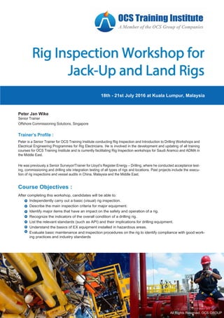
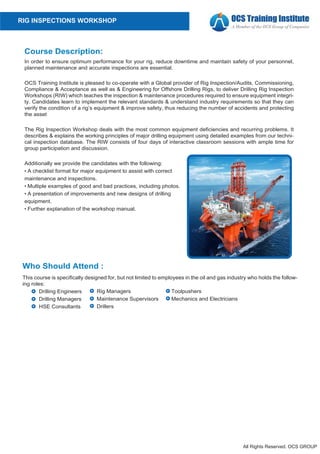
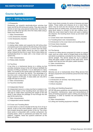

Peter is a senior trainer for OCS Training Institute who conducts workshops on rig inspections and drilling. He has extensive experience inspecting and testing rigs around the world. The document provides information on an upcoming 4-day Rig Inspection Workshop that Peter will facilitate. It details the course objectives, agenda, description, and registration information. The workshop will cover inspecting and evaluating the major equipment used on rigs, such as drawworks, BOPs, mud systems, engines, and more, to ensure safety and performance.