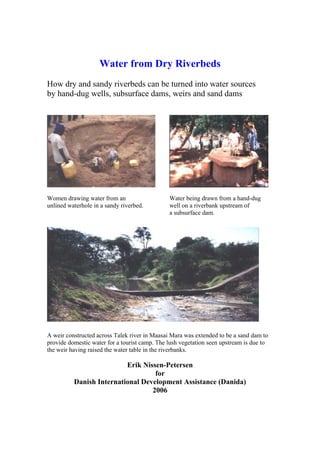
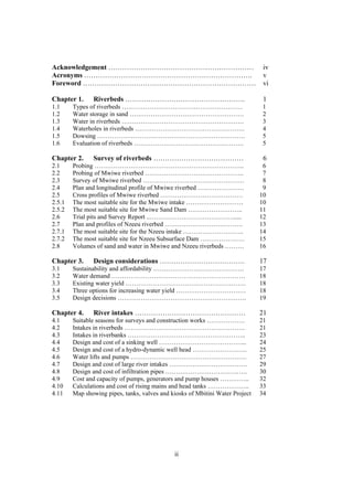
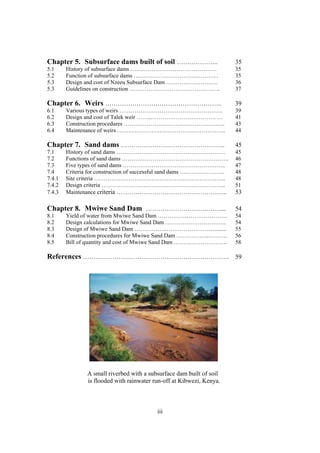
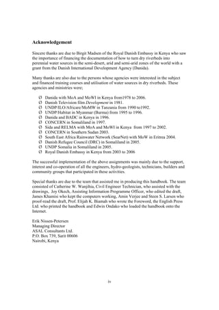
Water from Dry Riverbeds
How dry and sandy riverbeds can be turned into water sources
by hand-dug wells, subsurface dams, weirs and sand dams


Women drawing water from an                    Water being drawn from a hand-dug
unlined waterhole in a sandy riverbed.         well on a riverbank upstream of
                                               a subsurface dam.


A weir constructed across Talek river in Maasai Mara was extended to be a sand dam to
provide domestic water for a tourist camp. The lush vegetation seen upstream is due to
the weir having raised the water table in the riverbanks.

                          Erik Nissen-Petersen
                                   for
          Danish International Development Assistance (Danida)
                                  2006
Technical handbooks in this series :
Titles                                   Contents
1 Water for rural communities            Lessons learnt from Kitui pilot projects
2 Water supply by rural builders         Procedures for being rural contractors
3 Water surveys and designs              Survey, design and cost of water projects
4 Water from rock outcrops               Rock catchment tanks, masonry and earth dams
5 Water from dry riverbeds               Wells, subsurface dams, weirs and sand dams
6 Water from roads                       Rainwater harvesting from roads
7 Water from small dams                  Ponds and small earth dams built manually
8 Water from roofs                       Various types of roof catchments for domestic use


These handbooks can be obtained free of charge by either collecting them from the office of
ASAL Consultants Ltd., or by paying through bank transfer the cost of sending the manuals by
courier. For further details, please contact: asal@wananchi.com with copy to
asalconsultants@yahoo.com

Published by
ASAL Consultants Ltd. for
the Danish International Development Agency (DANIDA) in Kenya
Text, photos and sketches by
Erik Nissen-Petersen
Computer drawings and tracing by
Catherine W. Wanjihia
Editing by
Joy Okech
Proofs by
Amin Verjee and Steen S. Larsen
Printer
English Press, P.O. Box 30127, Nairobi, Kenya

Website by
Edwin Ondako
Distribution by
ASAL Consultants Ltd. P.O. Box 739, Sarit 00606, Nairobi, Kenya
asal@wananchi.com asalconsultants@yahoo.com
Fax/Tel : 254 (0) 202710296 Mobiles: 0733 619 066 and 0722 599 165
Website : www.waterforaridland.com
  Copyright
The copyright of this handbook is the property of the Royal Danish Embassy in Kenya.
Downloading from the internet and photocopying of the handbooks is permitted provided
the source is acknowledged.
                                            i

   Contents                                                                 Page
Acknowledgement ………………………………………………………                                           iv
Acronyms ……………………………………………………………….                                              v
Foreword …………………………………………………………………                                              vi

Chapter 1.     Riverbeds …………………………………………….                                     1
1.1     Types of riverbeds …………………………………………………                                 1
1.2     Water storage in sand ………………………………………………                               2
1.3     Water in riverbeds ………………………………………………….                                3
1.4     Waterholes in riverbeds …………………………………………….                             4
1.5     Dowsing …………………………………………………………….                                       5
1.6     Evaluation of riverbeds …………………………………………….                             5

Chapter 2.     Survey of riverbeds …………………………………                                6
2.1     Probing ……………………………………………………………..                                       6
2.2     Probing of Mwiwe riverbed ………………………………………..                             7
2.3     Survey of Mwiwe riverbed …………………………………………                               8
2.4     Plan and longitudinal profile of Mwiwe riverbed ………………….                9
2.5     Cross profiles of Mwiwe riverbed …………………………………                         10
2.5.1   The most suitable site for the Mwiwe intake ………………………                  10
2.5.2   The most suitable site for Mwiwe Sand Dam ……………………..                   11
2.6     Trial pits and Survey Report ..…………………………………......                     12
2.7     Plan and profiles of Nzeeu riverbed ……………………………….                      13
2.7.1   The most suitable site for the Nzeeu intake ………………………..                14
2.7.2   The most suitable site for Nzeeu Subsurface Dam …………………                15
2.8     Volumes of sand and water in Mwiwe and Nzeeu riverbeds ………             16

Chapter 3.     Design considerations ……………………………….                             17
3.1     Sustainability and affordability …………………………………….                       17
3.2     Water demand …………………………………………………… …                                    18
3.3     Existing water yield …………………………………………………                               18
3.4     Three options for increasing water yield ……………………………                   18
3.5     Design decisions …………………………………………………….                                 19

Chapter 4.     River intakes …………………………………………                                  21
4.1     Suitable seasons for surveys and construction works ………………             21
4.2     Intakes in riverbeds …………………………………………………                               21
4.3     Intakes in riverbanks ………………………………………………..                             23
4.4     Design and cost of a sinking well …………………………………...                     24
4.5     Design and cost of a hydro-dynamic well head ……………………..                25
4.6     Water lifts and pumps ……………………………………………….                              27
4.7     Design and cost of large river intakes ……………………………….                   29
4.8     Design and cost of infiltration pipes ……….……………………. ….                 30
4.9     Cost and capacity of pumps, generators and pump houses …………..          32
4.10    Calculations and cost of rising mains and head tanks ………………..          33
4.11    Map showing pipes, tanks, valves and kiosks of Mbitini Water Project   34


                                              ii
Chapter 5. Subsurface dams built of soil ………………..                      35
5.1     History of subsurface dams ………………………………………                     35
5.2     Function of subsurface dams ……………………………………. .                  35
5.3     Design and cost of Nzeeu Subsurface Dam ………………………              36
5.3     Guidelines on construction ……………………………………… ..                  37

Chapter 6. Weirs ………………………………………………..                                  39
6.1     Various types of weirs ………………………………………………                      39
6.2     Design and cost of Talek weir ……..……………………………. …               41
6.3     Construction procedures ……………………………………………..                    43
6.4     Maintenance of weirs …………………………………………….…..                     44

Chapter 7. Sand dams …………………………………………..                                45
7.1     History of sand dams …………………………………………………                       45
7.2     Functions of sand dams ………………………………………………..                    46
7.3     Five types of sand dams ………………………………………….…..                   47
7.4     Criteria for construction of successful sand dams …………………...   48
7.4.1   Site criteria ………………………………………………………. …..                       48
7.4.2   Design criteria ………………………………………………………..                        51
7.4.3   Maintenance criteria ……………………………………………..                       53

Chapter 8. Mwiwe Sand Dam ………………………………...                              54
8.1     Yield of water from Mwiwe Sand Dam ………………………………                54
8.2     Design calculations for Mwiwe Sand Dam …………………………..            54
8.3     Design of Mwiwe Sand Dam …………….……………………...........             55
8.4     Construction procedures for Mwiwe Sand Dam ……………..……….         56
8.5     Bill of quantity and cost of Mwiwe Sand Dam ……………………….         58

References ……………………………………………………………. 59


               A small riverbed with a subsurface dam built of soil
               is flooded with rainwater run-off at Kibwezi, Kenya.


                                          iii
Acknowledgement

Sincere thanks are due to Birgit Madsen of the Royal Danish Embassy in Kenya who saw
the importance of financing the documentation of how to turn dry riverbeds into
perennial water sources in the semi-desert, arid and semi-arid zones of the world with a
grant from the Danish International Development Agency (Danida).

Many thanks are also due to the persons whose agencies were interested in the subject
and financed training courses and utilisation of water sources in dry riverbeds. These
agencies and ministries were;

       Danida with MoA and MoWI in Kenya from1978 to 2006.
       Danish Television film Development in 1981.
       UNDP/ILO/Africare/MoMW in Tanzania from 1990 to1992.
       UNDP/Habitat in Myanmar (Burma) from 1995 to 1996.
       Danida and BADC in Kenya in 1996.
       CONCERN in Somaliland in 1997.
       Sida and RELMA with MoA and MoWI in Kenya from 1997 to 2002.
       CONCERN in Southern Sudan 2003.
       South East Africa Rainwater Network (SearNet) with MoW in Eritrea 2004.
       Danish Refugee Council (DRC) in Somaliland in 2005.
       UNDP Somalia in Somaliland in 2005.
       Royal Danish Embassy in Kenya from 2003 to 2006

The successful implementation of the above assignments was mainly due to the support,
interest and co-operation of all the engineers, hydro-geologists, technicians, builders and
community groups that participated in these activities.

Special thanks are due to the team that assisted me in producing this handbook. The team
consisted of Catherine W. Wanjihia, Civil Engineer Technician, who assisted with the
drawings, Joy Okech, Assisting Information Programme Officer, who edited the draft,
James Khamisi who kept the computers working, Amin Verjee and Steen S. Larsen who
proof-read the draft, Prof. Elijah K. Biamah who wrote the Foreword, the English Press
Ltd. who printed the handbook and Edwin Ondako who loaded the handbook onto the
Internet.

Erik Nissen-Petersen
Managing Director
ASAL Consultants Ltd.
P.O. Box 739, Sarit 00606
Nairobi, Kenya


                                             iv
Acronyms
ASAL       =   Arid and Semi-arid Land
ASALCON    =   ASAL Consultants Ltd.
BADC       =   Belgium Assisted Development Council
BQ         =   Bill of Quantity
cm         =   Centimetres
CONCERN    =   A British Non-governmental Organization
cu         =   Cubic metres
Danida     =   Danish International Development Agency
DRC        =   Danish Refugee Council
g          =   gauge
GL         =   Ground level
Hardcore   =   Crushed stones
ILO        =   International Labour Organization
ITDG       =   Intermediate Technology Development Group
Km         =   Kilometre
KVA        =   Kilo Volts Ampere
Ksh        =   Kenya Shilling equal to US$ 72.00
KW         =   Kilo Watt
KWSP       =   Kenya Water and Sanitation Programme
m          =   Metre
mm         =   Millimetre
m2         =   Square metre
m3         =   Cubic metre
Max.       =   Maximum
MoA        =   Ministry of Agriculture
MoWI       =   Ministry of Water and Irrigation
NGO        =   Non-governmental Organization
PVC        =   Poly Vinyl Conduits
RELMA      =   Regional Land Management Unit
RWSS       =   Rural Water and Sanitation Programme
SearNet    =   South East Africa Rainwater Network
Sida       =   Swedish International Development Agency
UNDP       =   United Nations Development Programme
UPVC       =   Ultra Poly Vinyl Conduits
Y8         =   8 mm twisted iron bar
Y10        =   10 mm twisted iron bar
WL         =   Water level


                                  v
FOREWORD
In dry land areas of Kenya, episodic shortages of water are quite common. In many areas,
women have to spend days traveling long distances with donkeys and camels looking for
water. Where the distances are too long, the people have been compelled to move with their
livestock to the water sources. Due to the long distances covered searching for water,
affected local people have had very limited productive time especially that devoted to
agriculture and livestock production. Experiences in dry land areas have showed that when
the water source is harnessed and conserved through watering points, local people and
women in particular have more time to concentrate in other household chores and income
generating activities.


At present in most of Kenya, local people are compelled to live close to permanent water
sources; agricultural activities are scattered and localized in transitional agro-climatic zones.
Thus it is pertinent that the supply of water for domestic, livestock and supplemental
irrigation uses be considered a top priority in managing hydrological and agricultural
droughts in dry land areas. This supply should be followed by a well planned distribution
network of watering points which will meet the water requirements for various uses and
minimize environmental degradation due to overgrazing or deforestation. Any development
or rehabilitation of water supply schemes should aim to ensure reliable and adequate water
supply and sanitation.


The socio-economic consequences of inadequate water supply in dry land areas of Kenya
are costly and manifest themselves in low labor productivity, poor enrollment of children in
schools, and livestock mortality due to drought and famine. Thus inadequate water supply
ultimately decreases per capita water demand, and crop and livestock productivity.
Consequently, water shortages reduce household water requirements, household food and
water security and incomes. The low incomes propagate the vicious cycle of poverty and
famine that must be overcome among affected rural communities.


The development of appropriate and affordable community water supply systems calls for
innovative rain and runoff water management technologies for domestic, livestock, and
supplemental irrigation uses. Some of the technologies that have proven to be effective and
sustainable in water resource development and management in dry land areas include:
runoff regulation and storage techniques (e.g. gully head dams, hafirs or waterpans, micro
dams, ground catchments (djabias), roof catchments, underground water storage tanks (shui
jiaos), barkads, and macro and micro catchment systems; and ground water sources such as
hand dug wells, shallow drilled wells, infiltration galleries of sand storage dams, and piped
water from springs.


                                               vi
Water from dry riverbeds as a hands on manual provides the requisite insights and
information on how surface runoff that is released into seasonal rivers as flash floods can
be harnessed and abstracted through appropriate technologies such as hand dug wells,
weirs and sand storage dams (sand and subsurface dams).
This hands-on handbook begins with a historical perspective/background information on
sandy riverbeds as reservoirs of good quality water and then goes on to look into the
survey and design considerations required before constructing hand dug wells, weirs and
sand storage dams (sand and subsurface dams). This manual has also addressed the
concern over when to develop these water sources by giving the suitable seasons for
surveys and construction works. The latter information is important because experiences
from emergency relief operations in the arid lands of Kenya (i.e. Turkana) have showed
that the construction of sand storage dams in times of drought cannot provide the badly
needed water to water deficit areas. Instead, these dams should be developed with a view
to being recharged during the rainy season and utilized in subsequent dry spells.
Another major contribution by this handbook to the development of water from dry and
sandy riverbeds is that of providing the necessary details on design, bills of quantities and
costs, construction and maintenance procedures of the three water supply systems namely
hand dug wells, weirs and sand storage dams. Alongside this, this handbook gives the
costs and capacities of pumps, generator sets and pump houses as well as the calculations
and costs of water conveyance and distribution systems.
Indeed the information provided by this handbook will be of immense use to recently
established (under the new Ministry of Water and Irrigation) water resource development
and management institutions in Kenya such as the Water Resources Management
Authority (WRMA), the Water Services Trust Fund (WSTF), the Regional Water
Services Boards, and the grassroots based Water Resources Users Associations
(WRUAs).


Prof. Elijah K. Biamah
Chairman/Head,
Department of Environmental and Bio-systems Engineering,
University of Nairobi,
P.O. Box 30197-00100,
Nairobi, Kenya
Email: biamahek@yahoo.com


                                             vii
Chapter 1.       Riverbeds

1.1    Types of riverbeds
Dry riverbeds are sandy and seasonal
water courses that transport run-off
rainwater from catchment areas, also
called watersheds, into rivers or swamps
once or a few times in a year.

Dry riverbeds are also called ephemeral
streambeds, seasonal water courses or
sand rivers. In Kenya they are called          2) Gullies originating from stony hills
luggah and in Arabic wadi.                     have a potential for sand dams consisting
                                               of medium coarse sand where 250 litres
Most of the rainwater being transported        of water can be extracted from 1 cu.m.
downstream in riverbeds appears as             of sand, i.e. an extraction rate of 25%.
flash-floods that can be several metres
high, and that thunder downstream with
the sound of a steam locomotive.

Flash-floods can uproot trees and other
vegetation growing on riverbanks and
fields. Homes, villages and towns may
also be flooded and people, livestock,
buildings and bridges washed away by            3) Riverbeds having catchments of flat
the muddy maelstroms of flash-floods.          farmland usually contain fine textured
                                               sand, that can only yield a maximum of
Riverbeds may be classified into 4             100 litres of water from 1 cu.m. of sand,
classes of potential water sources as          i.e. an extraction rate of 10%.
follows:


                                               4) Stony riverbeds containing boulders
                                               and fractured rocks have the lowest
1) The most potential riverbeds have           potential for water extraction due to
hilly and stony catchments that produce        seepage caused by the boulders and
coarse sand where up to 350 litres of          fractured rocks. This seepage is,
water can be extracted from1 cu.m. of          however, beneficial for replenishment of
sand, i.e.an extraction of rate of 35%.        boreholes situated on riverbanks.


                                           1
1.2        Water storage in sand
Sand consists of small stone particles            Therefore, much more water can be
that originate from stones and rocks              extracted from riverbeds containing
being broken down by the effects of               coarse sand than from riverbeds with
sunshine, rains and temperature                   fine textured sand.
variations.
                                                  No water can be extracted from
Voids, which are empty spaces, are                riverbeds containing silt, such as in sand
always found between sand particles.              dams whose spillways were built in
When dry riverbeds are flooded by rains           stages higher than 30 cm.
and flash-floods, the air in the voids is
pressed out by the water because it is            Water storage in sand has several
heavier than air.                                 advantages, such as:

When a dry riverbed is being flooded, it          1) Evaporation losses are reduced
looks as if the riverbed is boiling as tens       gradually to zero when the water level is
of thousands of air bubbles are being             60 cm or more below the sand surface.
pressed out of the sand. This process is
known as saturation.                              2) Livestock and other animals cannot
                                                  contaminate the water reservoir because
Fine textured sand has tiny voids that            it is hidden under a surface of dry sand.
get saturated slowly with water. Only
about 10% of water can be extracted               3) Mosquitoes, and insects that carry
from the volume of fine sand.                     water-borne diseases, cannot breed in
                                                  underground water reservoirs. Frogs,
Coarse textured sand has larger voids             snakes and other unpleasant reptiles and
and is therefore saturated much quicker           animals are also unable to live in, and
than fine sand. The volume of water that          pollute, water reservoirs in sand.
can be extracted from coarse sand is
about 35% of the volume of sand.                  Sand testing
                                                  The porosity and extractable capacity of
Silt and sand extractability was tested           sand are found by saturating 20 litres of
and classified as follows:                        sand with a measured volume of water.

             Silt   Fine   Me-      Coar-                               The water is then
                    sand   dium     se                                  drained out of the
                           sand     sand                                container and
 Size        <0.5   0.5 to 1.0 to   1.5 to                              measured by
 mm                 1.0    1.5      5.0                                 removing a plug
 Satu-                                                                  from the bottom of
 ration      38%    40%    41%      45%                                 the container.
 Water
 extrac-      5%    19%    25%      35%
 tion


                                              2
1.3      Water in riverbeds                     Ficus natalensis   Muumo           9 m to
Since time immemorial, riverbeds have                              Muumo           15 m
provided water for people and animals.          Ficus              Mkuyu           9 m to
                                                malatocapra        Mukuyu          15 m
During extreme droughts, when all other
                                                Gelia aethiopica   Mvungunya       9 m to
water sources have dried up, water can
                                                                   Muatini         20 m
still be found in riverbeds.                    Piptadenia         Mganga          9 m to
                                                hildebranditi      Mukami          20 m
Elephants, ant-eaters and some other            Acacia seyal       Mgunga          9 m to
wild animals have a special sense by                               Munini          20 m
which they can locate such places where
water is found in riverbeds.                    Since the above mentioned trees must
                                                have their tap root in the water table, the
Some rural people and most well-diggers         depth of a water-table can be found by
know that water can only be found at            knowing the depth of the tree’s tap root.
certain places in riverbeds. They can
also give a rough estimate on how deep          A rule of thumb states that the tap root
they have to dig before reaching the            of a tree has a depth equal to about ¾ of
water-table.                                    the height of the tree.
                                                The height of a tree can be found by
Their knowledge is based on the fact that       measuring the length of the shadow the
certain species of trees and vegetation         tree is casting on the ground and
must have roots reaching down and into          comparing it with the length of the
the water-table in order to survive             shadow of a stick 100 centimeters long.
droughts. This traditional information is
compiled in the table below.                    The two measurements should be taken
                                                in the sunshine of early morning or late
                                                afternoon when the shadows are longest.
Water-indicating vegetation
Botanical name   Kiswahili &       Depth
                 Kikamba           to
                 names             water-
                                   level
Cyperus                            3 m to
rotundus         Kiindiu           7m
Vangueria        Muiru             5 m to
tomentosa        Kikomoa           10 m
Delonix elata                      5 m to
                 Mwangi            10 m
Grewia           Itiliku Itiliku   7 m to
                                   10 m
Markhamia        Muu               8 m to       For example: If the stick’ shadow is 80
hildebranditi    Chyoo             15 m
                                                cm long, the ratio is: 80/100 = 0.8.
Hyphaene         Kikoko Ilala      9 m to
thebacia                           15 m
                                                If the tree’s shadow is 12 m long, then
Borassus         Mvumo             9 m to       the tree is: 12 m x 5 / 4 = 15 m high and
flabellierfer    Kyatha            15 m         the tap root and water level is at:
Ficus                              9 m to       15 m x ¾ = 11.25 m depth.
walkefieldii     Mombu             15 m


                                            3
1.4    Waterholes in riverbeds
The reason why some waterholes are              If riverbeds with impermeable floors
perennial and others are not, lies under        have water, then something must have
the sand, where it cannot be observed.          stopped the water from being drained
                                                downstream. What could that be?
1) The floors under the sand in
riverbeds can consist of soil, clay,            The answer is found by hammering iron
murram, black cotton soil, boulders,            rods into the sand of riverbeds at certain
fractured rocks or solid rock bars.             intervals. Such probing shows that most
                                                riverbeds have a floor under the sand
2) Where floors consist of permeable            that bulges up and down. These natural
(water-leaking) material, such as sandy         barriers, called dykes, give the answer.
soil, fractured rocks or large boulders,
water will seep into the underground
through the floor. This may be beneficial
for deep boreholes but certainly not for
extracting water from riverbeds.

3) If a floor consists of an impermeable
(water-tight) texture, such as clay,
clayey soil or murram, there is no
leakage through the floor. Water can            Water is found in this waterhole because
therefore be extracted from the riverbed,       the dyke prevents the water seeping
unless it has drained downstream and            downwards in the voids between the
left the riverbed dry.                          sand in the riverbed.
4) Riverbeds have downstream
gradients because they function as
drainage channels for rainwater run-off.
Water in riverbeds is therefore always
moving downstream, either on the
surface or between the sand particles
under the surface of riverbeds. Surface
flow of water can easily be observed
during floods but the subsurface flow           Where the floor bulges upwards it acts
can only be observed when water is              as an underground dyke that stops the
scooped out of waterholes.                      underground flow of water, as seen on
                                                probing points no. 10, 13, 15, 19 and 23.
The reason why some riverbeds have
water and others have not, lies in the          Where there is a depression in the floor
floor under the sand in riverbeds with          it accumulates water, as seen on probing
impermeable floors.                             points no. 9, 14, 16 and 21.
If riverbeds have impermeable floors but        These are subsurface water reservoirs in
no water, it is because the water has           the sand, from where water can be
been drained downstream by gravity.             extracted.


                                            4
1.5     Dowsing
Gifted persons can use dowsing to locate         1.6    Evaluation of riverbeds
underground water sources and                    The most potential stretches of a riverbed
underground dykes.                               are identified by walking in them together
                                                 with the community members who have
                                                 requested for assistance to improve their
                                                 existing water source or to construct new
                                                 ones in the riverbed.

                                                 First draw a sketch of the riverbed.

The tool consists of a 1m long brazing           Then walk and dowse, if capable of that,
rod cut in two halves and each half              in the riverbed while plotting the
having a 12 cm long handle.                      following information on the map:

                                                 1) Location and types of water-indicating
                                                 trees and vegetation.

                                                 2) Location of water-holes and their
                                                 depth to the water-table and quality of the
The two dowsing rods are held loosely            water.
and pointing downwards so that they can
swing freely. However, the hands must            3) Location and types of rocks and
be held steady to allow gravity to pull          boulders.
the rods down while they are parallel.
                                                 4) Location of calcrete, which is a salty
                                                 whitish substance that turns water saline.

                                                 5) Coarseness of the sand.

                                                 6) Location of hand-dug wells, boreholes
                                                 and weirs in the riverbed.

                                                 7) Names of houses, schools and road
Here is water.      Here is no water.            crossings near the riverbed.

When walking slowly over an unknown              After having compiled the information
underground water source, the rods will          listed above, the community is informed of
swing inwards. The force of the pull             the various possibilities for improving
indicates the depth and volume of water          their water supply. When an agreement is
in the ground.                                   made with the community, a detailed
                                                 survey with probing is implemented for
Although these traditional techniques are        the purpose of providing data for drawing
rather successful when applied by reliable       designs and estimating the yield of water,
persons, more precise data is required by        and the cost of construction, operation and
professionals.                                   maintenance.


                                             5
Chapter 2. Survey of riverbeds

2.1    Probing                                 The tools required for simple surveys as
When the most promising lengths of a           follows:
riverbed have been identified during the
evaluation walk, they are probed using
probing rods hammered into the sand.           1) Probing rods made of 16 mm (5/8”)
                                               iron rods for measuring depths of sand.


                                               Notches should be cut in the probing
                                               rods for every 25 cm to collect sand
                                               samples when the rods are pulled up.

                                               2) A circular
                                               levelling tool
                                               made of a
                                               transparent
                                               hosepipe for
                                               measuring the
                                               gradients of
                                               riverbeds.


The probing data is used for:

1)    Drawing a plan and profiles of the
riverbed to identify the deepest place         3) Two long tape measures, one
from which water should be extracted           hanging down vertically from the
and the most shallow place where the           horizontal one, to measure width and
wall for either a subsurface dam, a weir       depth of riverbeds.
or a sand dam can be constructed.              4) A tripod ladder for hammering
                                                   long probing rods into the sand.
2) Estimating the volume of sand in            5) A mason hammer.
the reservoir and the extractable volume       6) A 20 litres jerrycan with water.
of water from the sand.                        7) Half a dozen of transparent plastic
                                                   bottles with water.
3) Providing the required data for             8) A knife and writing materials,
drawing the designs and estimating the         9) The Probing Data Sheets shown on
costs of construction.                             the next page.


                                           6
2.2 Probing of Mwiwe riverbed
Parts of the following contents are based on the actual implementation of the Mbitini and
Kisasi Water Projects situated about 30 km south of Kitui township in Eastern Kenya.

The Mwiwe riverbed, which is the water source for the Mbitini project, was surveyed in
November 2004. The survey started where the Wingo riverbed joins the Mwiwe riverbed.
The procedure was as follows:

1) A probing rod was hammered down in the middle of the riverbed until it hit the floor
under the sand with a dull sound. Then the level of the sand was marked on the rod and it
was pulled straight up without twisting. The following data was noted on the data sheet:

1)   The depth of water is measured from the tip of the rod to the water indication mark.
2)   The depth of sand is measured from the marked sand level to the tip of the rod.
3)   The coarseness of sand is seen in the notches of the rod.
4)   The type of floor under the sand is seen at the tip of the rod.
5)   The width of the sand in the riverbed is measured.
6)   The height of the banks are measured with two long tape measures.
7)   The presence of water-indicating vegetation, waterholes, roads, etc. is noted.
8)   The next probing is measured at regular intervals, for example 20 metres.

Probing Data Sheet (m).          Location: Mwiwe riverbed            Date: 20/11/04
Probing     Distance Width    Depth to Depth     Type of  Floor     Height of    Items seen
number      between of        water     of sand sand      under the river banks on the
            probings riverbed                             sand      Left / Right banks
        1          0    20.80 No water      0.50  Medium       Clay 1.50 / 1.80       Wingo
        2      20.00    24.20 No water      0.25     Fine      Clay 1.30 / 1.60
        3      20.00    28.20 No water      0.28  Medium       Clay 1.30 / 1.70    Waterhole
        4      20.00    25.50 No water      0.32  Medium       Clay 1.42 / 1.84     Pawpaw
        5      20.00    23.40 No water      0.45   Coarse      Clay 1.30 / 1.65
        6      20.00    30.50 No water      0.85   Coarse     Rock 1.32 / 1.45 Acacia tree
        7      20.00    29.50 No water      0.76  Murram Soft rock 1.32 / 1.50          Rock
        8      20.00    33.00 No water      1.00   Coarse      Clay 1.97 / 1.55    Waterhole
        9      20.00    23.62      0.20     1.25  Medium       Clay 0.70 / 1.25      Fig tree
       10      20.00    23.62 No water      0.50  Medium       Clay 2.25 / 1.67    Tele. Pole
       11      20.00    29.60      0.10     1.00  Medium       Clay 0.70 / 1.35         Road
       12      20.00    32.90 No water      0.59  Medium       Clay 0.97 / 1.80 Mukengeka
       13      20.00    25.70 No water      0.55  Medium       Clay 1.33 / 1.76      Kiindiu
       14      20.00    20.00      2.00     3.00  Medium       Clay 1.50 / 1.68 Waterholes
       15      20.00    17.00 No water      0.75  Medium       Clay 1.32 / 1.56 Fence post
       16      20.00    26.00      0.10     1.25   Coarse      Clay 1.85 / 1.60 Orange tree
       17      20.00    22.69 No water      0.93   Coarse      Clay 1.00 / 1.45 Orange tree
       18      20.00    18.40 No water      0.50  Medium       Clay 1.20 / 1.53      Munina
       19      20.00    17.50 No water      0.50   Coarse      Clay 1.20 / 1.65 Fence post
       20      20.00    20.00      0.50     1.75   Coarse      Clay 1.46 / 1.58     Mwangi
       21      20.00    29.00      0.60     1.75   Coarse      Clay 1.75 / 1.67      Fig tree
       22      22.00    30.00 No water      0.88   Coarse      Clay 1.13 / 1.58     Musewa
       23      22.00    26.00 No water      0.45   Coarse      Clay 1.20 / 1.45      Kiindiu


                                              7
2.3    Survey of Mwiwe riverbed                The horizontal sighting line in the
                                               circular levelling instrument hit the pole
                                               0.8 metres above the level of the sand.
                                               The difference of 0.8 m in height
                                               between probing points No.1 and No. 23
                                               being 440 metres apart, gives a gradient
                                               of: 0.8 / 440 m x 100 m = 0.18%.

                                               Sand test


The heights and shape of the riverbanks
were measured using two long tape
measures, one hanging vertically down
from the other which was drawn tightly
between the top of the riverbanks.


The gradient of the riverbed was
measured by a person standing at
probing point No. 1 while sighting
downstream using the two horizontal            Samples of dry sand were taken and
water levels in a circular hosepipe that       filled in a 20 litres container for the
was filled halfway with water.                 purpose of measuring the porosity and
                                               the volume of water that can be
                                               extracted from the sand reservoir.

                                               The saturation of the sand was reached
                                               after adding 8 litres of water, giving a
                                               saturation rage of 40% (8 / 20 x 100).

                                               Then a small hole was made in the
                                               bottom of the container to drain the
                                               water out of the sand. In one hour, 5
Other persons were standing                    litres of water was extracted from the
downstream at probing point No. 23             sand. That gives an extractable capacity
while holding a long pole vertically.          of 25% (5 / 20 x 100).


                                           8
2.4 Plan and longitudinal profile of Mwiwe riverbed
A plan and a longitudinal profile was drawn according to the probing data on a sheet
of A3 mm graph paper which is 40 cm long and 28 cm wide.

The horizontal measurements were drawn to a scale 1:2000, which means that the
440 metres length of the riverbed was drawn as 22 centimetres long and the 20 metre
intervals between the probings were drawn as 1 centimetre long on the graph papers.


DOWNSTREAM                                                                UPSTREAM
Plan of Mwiwe riverbed.

The plan shows that the probed river has a length of 440 m and width varying from
17.5 m to 33.0 m. Water-indicating trees, e.g. Figs, Mwangi and Munina, grow along the
riverbed. Waterholes having water 7 months after the last rains were located at probing
point No. 10, 14 and 21 where the sand is deep. Water is trapped in the sand by
downstream dykes at points No. 11, 18 and 23, as see on the longitudinal profile below.


DOWNSTREAM                                                               UPSTREAM
Longitudinal profile of Mwiwe riverbed.


                                            9
The longitudinal profile on the former page shows that the sand is 3.0 m deep at point No. 14 and
1.75 m deep at point No. 21. Since both places are holding water 7 months after the last rain they
are the best extraction points in that part of Mwiwe riverbed. The next phase in surveying the
riverbed was to probe across at point No. 17 in order to learn of the volume of the depression and
its water yielding capacity.


2.5    Cross profiles of Mwiwe riverbed

2.5.1 The most suitable site for Mwiwe extraction point

The riverbed was probed from bank to bank at 2 metre intervals at point No. 14. To
confirm that point No. 14 was the deepest point, further probing was done both upstream
and downstream from that point.

          Probing data across the extraction point at No. 14 in Mwiwe riverbed
            Probing    Distance         Depth of sand     Type of sand   Type of floor
            No.        between                                           under the
                       probings m           m                            sand
                   1                2              0.75   Coarse sand    Sandy clay
                   2                2              3.25   Coarse sand    Sand
                   3                2              2.50   Coarse sand    Sandy clay
                   4                2              1.75   Coarse sand    Sandy clay
                   5                2              3.00   Coarse sand    Sand
                   6                2              1.50   Coarse sand    Sand
                   7                2              0.75   Coarse sand    Sandy clay
                   8                2              NIL    Coarse sand    Sandy clay


           LEFT BANK                                               RIGHT BANK
             Probing profile of No. 14 in Mwiwe riverbed where the sand is
             deepest and therefore the most suitable place for the intake.


                                              10
2.5.2 The most suitable site for the dam wall of Mwiwe Sand Dam
The longitudinal profile and several cross probings showed that the underground dyke at
point No. 18 was the most suitable for the Mwiwe Sand Dam as shown below.

          Probing Distance between Depth of      Type of sand        Type of floor
          No.     probings m       sand m                            under the sand
                0                2          0.85 Coarse sand         Clay
                1                2          1.35 Coarse sand         Clay
                2                2          1.30 Coarse sand         Clay
                3                2          1.70 Coarse sand         Clay
                4                2          1.30 Coarse sand         Clay
                5                2          1.60 Coarse sand         Clay
                6                  2            1.40 Coarse sand     Clay
                7                  2            1.10 Coarse sand     Clay
              7.5                0.5            0.40 Coarse sand     Clay


       LEFT BANK                                                       RIGHT BANK

       This cross profile shows the measurements of the most suitable underground dyke
       at No. 18 for Mwiwe Sand Dam. The design below was based on this profile.


                    Design of Mwiwe Sand Dam that was based on No. 18 cross profile


                                           11
2.6    Trial pits


Trials pits were excavated down to      Underground dykes can sometimes be located
the floor under the sand every 3 metres by vegetation growing in soil situated just
to confirm the correctness of the       below the sand surface.
probing.

The surveyors prepared a Survey Report with all details and data compiled of Mwiwe
riverbed. The report was handed over to a design engineer for his considerations which
are presented in the next chapter.

Thereafter the surveyors surveyed a much larger riverbed, Nzeeu, for 25,000 people in
Kisasi Water Project. The survey data is presented on the next pages.


                            On the left, a local expert is
                            using a pendulum to find
                            water under the ground.


                            On the right, a soda bottle
                            is used for grading a sand
                            sample


                                           12
2.7    Plan and profiles of Nzeeu riverbed


DOWNSTREAM                                                              UPSTREAM
Plan of Nzeeu riverbed

The surveyors started probing from the junction of Nzeeu and Kindu riverbed at point 0.
Thereafter they returned to point 0 and surveyed upstream as shown on these sketches.


RIGHT BANK                                                                LEFT BANK
Longitudinal profile of the probing in Nzeeu riverbed.

The plan and profile show a large underground water reservoir at No. 3 and an
underground dyke with a narrow point at probing point No. 13 which is a perfect
foundation for either a subsurface dam or a sand dam.


                                           13
2.7.1 The most suitable site for the Nzeeu extraction point
A cross profile of Nzeeu riverbed at probing point No. 3 on the longitudinal profile
confirms the large underground water reservoir from which water will be extracted.

      Probing data across the deepest point at No. 3 of Nzeeu riverbed
        Probing     Distance         Depth of        Type of sand   Type of floor
        No.         between          sand                           under the
                    probings m                                      sand
                                         m
                1                0               0   Fine sand      Clay
                2                3            2.50   Medum sand     Clay
                3                3            3.50   Coarse sand    Not reached
                4                3           4.50+   Coarse sand    Not reached
                5                3           4.50+   Coarse sand    Not reached
                6                3           4.50+   Coarse sand    Not reached
                7                3           4.50+   Coarse sand    Not reached
                8                3           4.50+   Coarse sand    Not reached
                9                3           4.50+   Coarse sand    Not reached
               10                3           4.50+   Coarse sand    Not reached
               11                3            3.50   Coarse sand    Not reached
               12                3            2.50   Coarse sand    Clay
               13                8            2.00   Coarse sand    Clay
               14                8            2.00   Coarse sand    Clay
               15                8            2.00   Coarse sand    Clay


RIGHT BANK                                                                   LEFT BANK

Cross profile of Nzeeu riverbed at point No. 3 (A-A) which will be the extraction point.


                                                14
2.7.2 The most suitable site for the dam wall of Nzeeu Subsurface Dam
A cross profile of the underground dyke and narrow riverbed at point 13 confirms the
location of the most shallow place for either a subsurface dam, a weir or a sand dam.

          Probing data across the shallow dyke at No. 13 (B-B) of Nzeeu riverbed
            Probing Distance         Depth of sand     Type of sand   Type of floor
            No.     between              m                            under the
                    probings m                                        sand
                  1              0              1.50   Coarse sand    Sandy clay
                  2              3              1.50   Coarse sand    Sand
                  3              3              2.00   Coarse sand    Sandy clay
                  4              3              1.75   Coarse sand    Sandy clay
                  5              3              1.75   Coarse sand    Sand
                  6              3              1.50   Coarse sand    Sand
                  7              3              1.00 Coarse sand      Sandy clay


         RIGHT BANK                                                  LEFT BANK
         Cross profile of Nzeeu riverbed at probing point No. 13 (B-B). The profile
         was used for the design of the subsurface dam as shown below.


                                           15
2.8     Volumes of sand and water in Mwiwe and Nzeeu riverbeds
The porosity and extractable percentage of water from the sand in Nzeeu riverbed was
found to be 35% and 30% respectively.

The approx. volume of a dam reservoirs can be found by this rule of thumb:
Maximum depth x maximum width x maximum throw-back / 6 = Volume.
(A through-back is the horizontal length of water in a dam).

The volume of sand and water in the reservoirs of the two riverbeds were found to be:
          Max. depth Max. width Throw-back   1/6 Sand       % Water    Water
              m         m           m            Volume m3 extraction  volume m3
Mwiwe           3.25      25.70        40.00 1/6        557         25          139
Nzeeu           5.00      66.00       380.00 1/6     20,900         30        6,270

An unknown volume of subsurface flow of water in the sand replenishes the two
reservoirs which should be added to the volume of water shown above.

In order to increase the yield of water from Mwiwe riverbed it was decided to construct a
a sand dam upon the dyke at No. 18, because that would increase the storage capacity
from 139 m3 to 2,997m3, as shown under WL 4 in the table below.

Three options for increasing the volume of sand and water in Mwiwe riverbed
        Max. depth Max. width        Throw-back     1/6 Sand          % Water    Water
             m            m              m                Volume m3 extraction   volume m3
WL 1            3.25          25.70          40.00 1/6           557          25         139
WL 2      0.8 + 3.25          26.00         260.00 1/6         4,563          25       1,141
WL 3      1.4 + 3.25          28.00         300.00 1/6         6,510          27       1,758
WL 4      2.3 + 3.25          30.00         360.00 1/6         9,990          30       2,997

Three options for increasing the volume of sand and water in Nzeeu riverbed
        Max. depth Max. width        Throw-back     1/6 Sand           % Water    Water
             m            m              m                Volume m3 extraction    volume m3
WL 1            5.00          66.00         380.00 1/6        20,900           30       6,270
WL 2      0.8 + 5.00          68.00         420.00 1/6        27,608           30       8,282
WL 3      1.4 + 5.00          70.00         440.00 1/6        32,853           30       9,856
WL 4      2.3 + 5.00          72.00         480.00 1/6        42,048           30     12,614

Key:
WL 1 = Existing natural reservoir in the riverbeds
WL 2 = Increased volume by a subsurface dam wall built to 30 cm below sand level
WL 3 = Increased volume caused by a weir built to 30 cm above sand level
WL 4 = Increased volume caused by a sand dam wall built to 150 cm above sand level

A Survey Report was then given to the engineer to determine whether the dam should be
a cheap subsurface dam or a low cost weir or the more expensive sand dam. The
considerations for this assessment are described in the next chapter.


                                           16
Chapter 3. Design considerations

3.1    Sustainability and affordability
Sustainability and affordability are two key words that should always be remembered
when designing water projects.

Sustainability of water projects can be achieved by designing tested and simple
structures that the community can construct, operate, maintain and repair themselves.

For example, initially it was planned to drill two boreholes and equip them with
submersible pumps at Mbitini and Kisasi water projects at a total cost of about Ksh 3
million. Instead, some local builders were contracted to sink two hand-dug wells with
infiltration pipes at a total cost of Ksh 425,000, all inclusive. Not only was the
construction cost reduced by Ksh 2.5 million but it was much easier and cheaper for the
community to service the pumps in the hand-dug wells than it would have been in the
boreholes.

Affordability is also achieved by designing tested and simple structures using a
maximum of locally available skills and materials that the community can afford to
procure, construct, operate, maintain and repair. The example described above with
boreholes versus hand-dug wells describes exactly what affordability is all about.

The supply capacity of a water project should be able to satisfy a community’s water
demand for the next 20 years. If the supply capacity is less than the demand, people will
complain that their water supply is insufficient and they have wasted their money and
time. Where a water project is over-designed, the construction works and operation costs
are higher than necessary and the extra cost has to be levied on the sale of water. The
supply capacity and the water demand should therefore balance.

Another factor to consider is the population increase. When water is available, many
people living outside the project area will be attracted to settle in the project area. The
supply capacity must also include this population in addition to the normal increase.


Water is sold at kiosks from Ksh 2 to Ksh 4        A Kiosk Attendant’s sales record is
per 20 litre jerrycan. The price of water          checked. The income from sale of water
depends on the cost of operation, main-            must be sufficient to pay for salaries,
tenance and repairs.                               fuel, operation, maintenance and repairs.


                                              17
3.2     Water demand
With reference to an appraisal report produced by Development Impact Consulting (DIC)
in August 2004, the combined water demand for Mbitini is projected as shown in the
table below.

Daily Water Demand for Mbitini. The water demand by Kisasi is similar to Mbitini.
Category                                 m3/day    m3/day        m3/day      m3/day
                                         2004      2005          2015        2025
General population                             169       172           210         256
Livestock units                                 20         20            23         26
Schools                                         11         11            14         17
Health and Adm. Centres                          5           5            5          5
Shopping centres                                12         14            18         21
Total daily water demand (m3/day)              217       222           270         325
Total annual water demand (m3/year)         80,000    81.000        98,000     118,000
Demand in 6 months without rains            40,000    41,000        49,000      59,000


3.3     Water yield in year 2004

Volume of sand and water in the underground reservoirs
           Max. depth Max. width Throw-back   1/6 Sand       % Water    Water
               m         m           m            volume m3 extraction  volume m3
Mwiwe            3.25      25.70        40.00 1/6        557         25          139
Nzeuu            5.00      66.00       380.00 1/6     20,900         30        6,270


3.4     Three options for increasing the water yields
The three available options for increasing the water yields are to construct dam walls for
either:

1)      A subsurface dam built of soil to 30 cm below the surface of sand in a riverbed, or

2)      a weir built of concrete or rubble stone masonry to 30 cm above the sand level, or

3)      a sand dam built of concrete or rubble stone masonry to a maximum of 5 metres
        above the level of sand in a riverbed.

These dam walls should be constructed on the identified underground dykes situated
downstream of existing underground water reservoirs.

In other riverbeds, the three types of riverbed dams should, preferably, be constructed on
underground dykes. The dams can, however, also be built in riverbeds not having
underground reservoirs or underground dykes.


                                            18
3.5    Design decisions
The following decisions on the designs were taken on the basis of the evaluation report
and the considerations described above as well as during several meetings with the Kisasi
and Mbitini project committees:


3.5.1 Decision on extraction point in Mwiwe riverbed
As mentioned above, it was found more sustainable and affordable to lay infiltration
pipes in the riverbed to drain water into a hand-dug well to be sunk in the riverbank,
instead of drilling a borehole and equipping it with a submersible pump.

The extraction point will consist of 72 metres of infiltration pipes made of perforated 160
mm UPVC laid in crushed stones as deep in the riverbed as the water level would allow
at point No. 14 in Mwiwe riverbed. The infiltration pipes will be laid with a gradient
towards the riverbank to facilitate water flowing into a hand-dug well that will be sunk in
the riverbed.

The hand-dug well will have a diameter of 3 metres and be sunk as deep as the water
table will allow. The well will be built of curved concrete blocks reinforced together on a
circular foundation/cutting ring of reinforced concrete.

Extraction of water from the well will consist of a surface pump powered by a diesel
generator that will be installed in a pump house to be constructed.

The pump will deliver the water to a 100 m3 head tank to be constructed of concrete
blocks and situated 0.96 km from the pump at an elevation of 80 metres above the pump.
From this head tank water will gravitate through 2 water tanks and 22.9 km of pipelines
to 11 water kiosks.


3.5.2 Decision on a sand dam in Mwiwe riverbed
For Mwiwe riverbed it was decided to construct a sand dam of rubble stone masonry to a
height of 1.5 metres above the existing sand surface at probing point No. 18. The sand
dam will raise the water table from 1.7 metres below the sand level to 1.5 metres above,
which is a total of 3.2 metres. This will increase the storage capacity from the existing
139 m3 to 2,997 m3 as shown under WL 4 (Water Level 4) in the former chapter.

After the infiltration pipes have been laid in the riverbed and the hand-dug well has been
sunk as deep as possible, the water table in the riverbed will be raised by construction the
sand dam in the required stages.


                                             19
3.5.3 Decision on extraction point in Nzeeu riverbed
The extraction point in Nzeeu riverbed will be a replica of the extraction point in Mwiwe
riverbed, except for the pump, which will deliver the water to a 50 m3 elevated head tank
to be constructed of steel plates. The tank will be situated 5.3 km from the pump at an
elevation of 154 metres above the pump. From this head tank water will gravitate through
2 water tanks and 16 km of pipelines to 10 water kiosks.

3.5.4 Decision on a subsurface dam in Nzeeu riverbed
The selected option for Nzeeu was a subsurface dam whose wall will be built of soil to 30
cm below the existing sand surface, which will raise the water table 170 cm. This will
increase the water storage capacity from the existing 6,270 m3 to 8,282 m3.

The subsurface dam will have two purposes, namely, a) to increasing the yield of water,
and, b) to compare its construction cost and performance with the sand dam at Mwiwe.


            Survey and design data are being compiled into a Survey Report by some
            participants of a training course dealing with water from dry riverbeds.


                                           20
Chapter 4. Riverbed intakes

4.1    Suitable seasons for surveys and construction works

Surveys of riverbeds should always be carried out in the driest seasons when water levels
are at their lowest. Information and mobilization of communities should also be
implemented in the dry seasons when water supplies are scarce and people are concerned
about their water supplies. Designs, bills of quantities, costs and work plans can be drawn
up during rainy seasons.

Construction of water projects should always start with sinking of the wells and laying of
the infiltration pipes and that should always take place during a dry season. By doing so,
the minimum yield of water can be known and used for calculating the required capacity
of the pump and generator, pipelines, water kiosks, etc.

The minimum yield is also used to determine whether the riverbed can supply sufficient
water or if a subsurface dam, weir or sand dam has to be built to increase the yield of
water.
If so, the construction work of such structures should take place in the beginning of the
short dry season or in the middle of the long dry season when there is no risk of an
unexpected thunder shower that can flood the construction site.

Excavation of trenches for pipes, and the laying of pipes, should also take place in the dry
season when the fields have been harvested to avoid spoiling crops in the field. Other
activities that demand much manual labour should also be implemented when the farmers
are less busy in the dry seasons.

Another big advantage of constructing water projects during dry seasons is that the
provision of water is usually the biggest issue during those periods. It is therefore fairly
easy to mobilize and organize people to carry out manual work.

More detailed information on survey and design is given in another handbook of this
series called Water Surveys and Designs.

4.2    Intakes in riverbeds
There are several technologies for lifting water from riverbeds that are affordable and
sustainable for individuals and community water projects.


The oldest and simplest method is to dig a
waterhole in a riverbed and use a calabash
cut in half to scoop water into a calabash or a
jerrycan.


                                              21
A safer and cleaner option is to sink a hand-
dug well next to the waterhole in a riverbed.


Hand-dug wells situated in riverbeds must be
equipped with a well-head to prevent the well
shaft being filled with sand during floods such
as this hydro-dynamic well-head used in
Sudan.


Another type of hydro-dynamic well-head is
shaped as a wedge to break the force of
floods.


A well-shaft can also be lined with worn-out
lorry tyres and closed by a lid made from the
bottom of an oil-drum.


                                            22
4.3 Intakes in riverbanks
Although sinking of wells directly into riverbeds is the cheapest way to extract water, the
wells might be damaged by unusually large flash-floods. It is therefore safer to build
hand-dug wells on the riverbanks and draw water from there provided the underground
soil is sandy soil that allows water to seep into the hand-dug wells.

If underground water cannot seep into a hand-
dug well, an infiltration pipe can be laid in a
trench to drain water into the hand-dug well.
The design can be made cheaper by filling the
trench with stones covered with polythene
sheeting instead of laying the infiltration pipe.


Well shafts can be lined with burnt bricks
when built upwards from the bottom of hand-
dug wells. However, this procedure is risky
because collapsing soil can bury the builders
alive.

A safer method is to build sinking wells
whereby curved concrete blocks are reinforced
together onto a foundation ring made of
concrete. The foundation ring and infiltration
course are built at ground level in riverbeds.

Then sand is removed from the inside of the
shaft causing it to sink into the sand. When the
top of the shaft has sunk to ground level, more
blocks are added onto the shaft. Sand is then
removed and the shaft sinks. The procedure is
repeated until the shaft has reached its final
depth.

Concrete culverts can be sunk in a similar way
but they are more difficult to handle due to their
weight.


The cost of lining well shafts can be reduced by
placing a large perforated PVC pipe in the centre of
the excavation and filling stones and gravel all
around it upto the ground level.


                                              23
4.4 Design and cost of a sinking well


                                                A tool made of iron for cutting grooves


Plan of well-shaft and curved concrete block


                                                 A groove being cut for a foundation
                                                 ring with the tool seen above. The
                                                 groove will be filled with reinforced
                                                 concrete.

                                                 Curved concrete blocks are made of
                                                 mortar in the ratio 1:5 and compacted
                                                 into a mould made of iron sheets.

                                                 It takes 16 blocks to make a circular
            Section of well-shaft                course with a diameter of 140 cm and
                                                 112 blocks to build 1 metre of shaft.


                                           24
4.5    Design and cost of a hydro-dynamic well head
A hydro-dynamic well head can be built around a well shaft directly into riverbeds to
prevent the well shaft being damaged or filled with sand from flash-floods.


The lay-out of a hydro-dynamic well head           Foundation being built of rubble
in the middle of a riverbed.                       stones reinforced with barbed wire.


A well head is constructed of rubble stones     An open steel cover over the well shaft
embedded in mortar, 1:4, and reinforced with    should be in the position shown to
barbed wire and chicken mesh.                   allow flash-floods to close the lid if
                                                people have forgotten to close it.


              A hydro-dynamic well head in the middle of a riverbed.


                                           25
Bill of quantity and cost of a well with hydro-dynamic well head, Ksh
Description        Unit               Quantity       Unit cost    Total Value of
6 metre deep hand-                                                 cost community
dug well with a                                                         contribution
hydro-dynamic
well head

Labour cost
Supervisor          Supervisor         3 days        1,200/day    3,600
Contractor          Contractor         6 days          800/day    4,800
Artisan             1 mason           24 days          200/day    4,800        4,800
Trainees            2 trainees        24 days          100/day    4,800        4,800
Labourers           4 labourers       24 days          100/day                 9,600
Cost and value of                                                18,000       19,200
labour
Materials
Cement              50 kg bags        26 bags             600    15,600
Weldmesh            1.2 m. x 2.4 m    1 sheet             400       400
G.I. wire           4 mm              20 kg                50     1,000
Chicken mesh        0.9 m x 30 m      4 meters            100       400
Barbed wire         Gauge 12.5        10 kg                80       800
Windlass            Two handles       1 unit            3,000     3,000
Iron bar            Y12 mm            1 length            500       500
River sand          Tonnes            4 tonnes            200
Crushed stones      2.5 mm            2 tonnes            600     1,200        1,200
Rubble stones       Tonnes            4 tonnes            200       600          600
Water               210 litre drums   10 drums            100                  1,000
Cost and value of
materials                                                        23,500        3,600
Transport cost
Trailer loads       3 tonnes          4 loads             900     3,600        1,800
Cost of transport
Total cost and
value                                                            45,100       24,600
Total cost                                                       69,700

The first part of a well shaft has been built
onto the foundation ring in an excavation dug
as deep as safety allows in a riverbed.

Insulated electric wires bent as U’s are inserted
in the mortar between the blocks in the lowest
part of the well shaft. When the sinking of the
shaft has been completed, the wires are pulled out,
thereby creating many small holes through which
water can seep into the well shaft. Also, note the
bent iron bars that are mortared into the shaft to
function as a ladder.


                                                26
4.6 Water lifts and pumps
                                              .


                                              .


                                                        A hand-operated pump with a cylinder
                                                        head made of concrete.


      Water can be drawn by several types
      of lifts and pumps. The simplest and
      cheapest is a bucket tied to a rope.
                                                           A foot-operated money-maker pump.


      A windlass made of a few Sisal poles.


                                                                A direct action pump.
      A windlass with an iron handle.
.


                                                                           A

         A rope and washer pump.                       A broken down India Mark II hand pump
                                                       replaced with a windlass made of Sisal.


                                                  27
Shallow water pumps (Reference Technical paper No. 13, ITDG).


      Deep water pumps


                               28
4.7 Design and cost of large river intakes

According to the evaluation report, each of the intakes at Mwiwe and Nzeuu riverbeds is
required to supply 217,000 litres (217 m3) of water daily, which amounts to 80,000 m3
annually equal to 40,000 m3 during a 6 month period without flooding of the riverbeds.

For each of the two intakes, this yield of water was obtained by sinking a well shaft made
of curved concrete blocks on a foundation ring with an internal diameter of 300 cm. Short
lengths of insulated electric wires were bent into a “U” shape and inserted in each course
of the concrete blocks for every 30 cm with the U facing inwards. The well shaft was
sunk as deep as a petrol-powered suction pump could remove the inflowing water.

When the capacity of the pump was reached at about 4 metres depth, the internal
diameter of the shaft was reduced to 110 cm in order to reduce the inflow of water. The
well-diggers then sunk the well shaft to an additional 3 metres before the inflow of water
became too much for the diggers and the pump. When the shaft had reached its final
depth, the insulated bent wires were pulled out of the shaft, each wire leaving two small
infiltration holes in the shafts for replenishing of the well.


A small well shaft being sunk inside a wide             The completed well head with the
well shaft of a river intake.                           pipe from the well to the pump.


Plan and section of the intake wells at Mwiwe and Nzeeu (mm).


                                              29
Bill of Quantity and cost of the Nzeeu intake well
Description             Unit            Quantity           Unit cost     Total cost   Value of
8 m deep intake well                                       2005          2005         community
                                                           Ksh           Ksh          contribution
Labour cost
1 Surveyor              Surveyor               2 days      1,200/day       2,400
1 Supervisor            Supervisor           10 days       1,200/day      12,000
1 Contractor            Contractor        1 x 20 days        800/day      16,000
2 artisans              Artisan          2 x 20 days         200/day       8,000         8,000
2 trainees              Trainees         2 x 20 days         100/day       4,000         4,000
10 labourers            Labourers        10 x 20 days        100/day      20,000        20,000
Cost of labour                                                            62,400        32,000
Materials
Cement                  50 kg bags             10            600           6,000
River sand              Tonnes                  3            200             600          600
Crushed stones          Tonnes                  3            600           1,800         1,800
Curved well blocks      Blocks                700             50          35,000        14,000
Galvanised wire, 4mm    Kg                     50            150           7,500
Iron bar, Y8            20 m length            10            500           5,000
Dewatering pump         Days                   10 days       800           8,000
Cost of materials                                                         63,900        16,400
Transport of
materials
Tractor trailer loads   3 tonnes              1 load          900           900           900
Cost of transport                                                           900           900
Cost and value                                                           127,200       49,000
Total cost                                                               176,200


4.8    Design and cost of infiltration pipes
In order to increase the recharge even further, 72 metres of 160mm PVC pipes, into
which thousands of small holes were burnt with red-hot nails, were connected to the
intake. The infiltration pipes were laid in crushed stones as deep as possible and with a
gradient towards the intake well to enable the water to drain from the sand into the intake.


Infiltration pipe connecting to the intake.            A flooded trench for infiltration pipes.


                                                30
Plan of the infiltration pipes laid deep in the sand of the riverbed.

Bill of Quantity and cost of 72 metres of infiltration pipe
Description                       Unit         Quantity     Unit cost      Total       Value of
Perforating and laying 72                                                  cost        community
meters of 160 mm PVC pipe                                   2005           2005        contribution
deep in a riverbed and sloping
towards a well in the riverbank                               Ksh            Ksh         Ksh
Labour cost
1 Surveyor                        Surveyor        4 days    1,200/day       4,800
1 Supervisor                      Supervisor      6 days    1,200/day       7,200
1 Contractor with                 Contractor 1 x 15 days      800/day      12,000
2 artisans and                    Artisans   2 x 15 days      200/day       6,000               6,000
4 trainees                        Trainees   4 x 15 days      100/day       6,000               6,000
10 labourers                      Labourers 10 x 15 days      100/day      15,000              15,000
Total cost of labour                                                       51,000              27,000
Materials
Dewatering suction pump           8 days                             800     6,400
Perforated PVC pipes,160 mm       6 m length     14 pipes          3,100    43,400
Cost of materials                                                           49,800
Transport of materials
Tractor trailer loads             3 tonnes      1 load              900         900               450
Cost of transport                                                               900               450
Cost and value                                                             101,700             27,450
Total cost and value                                                       129,150


                                               31
4.9    Cost and capacity of pumps, generators and pump houses


The pump in the Nzeeu pump house is a
Grundfoss CR15-17, 15.0 KW, 3 Phase
booster pump, with a capacity of 19m3/hr at
154 m head. Together with a control panel
and 60A isolator, float switch, chlorine
doser and installation the unit cost was
Ksh 560,305 in December 2004.

The pump in the photo is a Grundfoss
CR32-6, 11.0 KW, 3 Phase electric booster
pump with a capacity of 32 m3/hr at 71 m
head, that is installed in the Mwiwe pump
house. Together with accessories and
installation the cost was Ksh 558,200 in December 2004.


The diesel generator seen in the photo is an
Atlas Copco 41, KVA, QUB41 that powers
the Mwiwe pump. The cost was Ksh
876,550 in December 2004.

The Nzeeu pump is also powered by an
Atlas Copco diesel generator with a bigger
capacity of 41 KVA, QUB41, that powers
the pump. The cost was Ksh 876,550 in
December. 2004.


The Nzeeu pump house seen in the photo is
similar to the Mwiwe pump house. Both
houses have a private room for the Pump
Operator.

The cost of the pump house with a fence
was Ksh 793,866, including the value of
local labour and materials.


                                               32
4.10 Calculations and cost of rising mains and head tanks
The head tank for the Mbitini Water Project
is a 100 m3 tank built of concrete blocks at a
cost of Ksh 797,590. The tank is situated at
a distance of 0.916 km from the Mwiwe
intake at a height of 35.1 m above the
intake. The pumping head with 100 mm G.I
pipe delivering 30 m3/hr is:

Delivery head                   = 35.1 m
Frictional losses               = 25.7 m
Tank height                     = 3.0 m
10% residual (extra) head       = 6.4 m
Required pump capacity            70.2 m
Capacity of installed pump        71.0 m


The head tank for the Kisasi Water Project is
a 50 m3 elevated tank made of steel plates
costing Ksh 1,277,621. The tank is situated
at a distance of 5.3 km from the Nzeeu
intake and at a height of 74.2 m above the
intake. The pumping head, with 100 mm and
80 mm G.I. pipes, delivering 19 m3/hr is:

Delivery head                   =    74.200 m
Frictional losses               =    57.023 m
Tank height                     =     8.000 m
10% residual (extra) head       =     13.922 m
Required pump capacity              153.145 m
Capacity of installed pump          154.000 m


The cost of the rising main pipes were:

 Intake to head tank    Km       Ksh
 Nzeuu to steel tank    5.310    7,461,435
 Mwiwe to block tank    0.916    1,878,867

Water is delivered from the head tanks
through Distribution pipelines to the water
kiosks by means of gravity, as shown on a
map of the Mbitini project area on the next


                                             33
                                              34
page.
4.11 Map showing pipes, tanks, kiosks and valve chambers of Mbitini
Water Project.


            Mwiwe
            riverbed


        0        1     2     3      4       5      6       7      8       9     10 km


More technical details and costs on the Mbitini Water Project are given in another
handbook of this series: Water Surveys & Designs.


                                            34
                                           23
Chapter 5. Subsurface dams built of soil

5.1     History of subsurface dams

The oldest subsurface dams known were constructed in the almost waterless area around
Dodoma, in then Tanganyika and now Tanzania, when the railway was built around
1905. The purpose of the subsurface dams was to provide water for the steam
locomotives which they successfully did so for many decades.

A subsurface dam was built of soil and documented by Bihawana Mission near Dodoma
in the early 1950s and is still functioning well. A similarly successful subsurface dam
was built in the same area in the 1920s. Several subsurface dams were built of various
materials, such as soil, burnt bricks, concrete blocks and reinforced concrete during a
training course for ILO in the Dodoma region in 1991. Many more subsurface dams are
probably located in various places, but if so, they are be invisible below the sand surface
of riverbeds.

5.2     Function of subsurface dams
Should the water yield from a river intake be insufficient for the demand, then a
subsurface dam can be constructed cheaply of soil. The function of a subsurface dam is:

a)      Block the underground flow of water between the voids in the sand
b)      Raise the water level in the sand to about 30 cm below the surface of a riverbed.

With regard to Nzeeu riverbed, it was decided to construct a subsurface dam of soil that
would increase the yield from the existing 6,270 m3 of water to 8,282 m3 which, together
with the substantial underground replenishment would be sufficient to meet a dry season
demand of 40,000 m3.


      Longitudinal profile combined with a three dimensional view of a subsurface dam
      built of soil, and a hand-dug well built in the deepest part of the riverbed.


                                            35
5.3     Design and cost of Nzeeu Subsurface Dam


                      P
                      l
                      P
                      l
                      Plan and section of Nzeeu subsurface dam (mm)

 Bill of Quantity and cost of Nzeuu Subsurface Dam
  Description               Unit            Quantity       Unit cost   Total cost   Value of
                                                           2005        2005         community
                                                           Ksh         Ksh          contribution
  Labour cost
  Surveyor/designer         Surveyor         1 x 2 days    1,200/day       2,400
  Supervisor                Supervisor       1 x 6 days    1,200/day       7,200
  Contractor                Contractor       1 x 22 days     800/day      17,600
  Artisans                  Artisans         2 x 20 days     200/day       8,000            8,000
  Trainees                  Trainees         4 x 20 days     100/day       8,000            8,000
  Labourers                 Labourers       10 x 20 days     100/day                        8,000
  Cost of labour                                                          43,200           24,000
  Materials
  Clayey soil               Tonnes                69          100          6,900            6,900
  Cost of materials                                                        6,900            6,900
  Transport of materials
  Hiring suction pump
  Tractor trailer loads     3 tonnes Days     23 loads           900      20,700           10,350
  Hiring dewatering pump                       4 days            800       3,200
  Cost of trans. and pump                                                 23,900           10,350
  Cost and value                                                          74,000           41,250
  Cost of subsurface dam                                                 115,250


                                             36
The sand in a riverbed has been           The excavation is being filled with
       removed and the 60 cm deep key            compacted moist clayey soil by
       has been excavated in the floor.          a community in Myanmar (Burma)


       Two subsurface dams being build by self-help communities in Makueni, Kenya


5,3    Guidelines on construction
In order to get a maximum volume of water for a minimum of work and investment, the
walls of subsurface dams, weirs and sand dams should, whenever possible, always be
constructed on underground dykes that are situated downstream of underground water
reservoirs, identified by waterholes and water-indicating vegetation.

When a suitable site has been identified in a riverbed, the most clayey soil for
construction of the dam wall has to be found. This is done by collecting soil samples
from nearby riverbanks and fields. The equipment for analyzing the soil samples consists
of plastic bottles of equal size, of which the caps have been removed and the bottoms cut
off.

The bottles are placed upside down in the sand, or sloping against a wall, and filled
halfway with soil samples. Water is poured on top of the soil samples several times. After
some minutes it can be observed which soil sample has the slowest infiltration rate due to
having the highest clay content. This soil is the most suitable for building the dam wall.


                                           37
Soil samples being tested for their clay content by pouring water into the soil samples.
The sample having the slowest infiltration rate is the most suitable for dam walls.
When a suitable site has been identified, all the sand in the riverbed is removed in a 3
metre wide stretch between the two riverbanks, so that the floor under the sand is fully
exposed.

Thereafter a 100 cm wide trench, called a key, is excavated into the floor right across the
riverbed and into the two riverbanks. The depth of the key must be at least 60 cm into
solid soil to prevent seepage under the dam wall.

The best clayey soil identified by the testing mentioned above, must now be transported
to the dam site by e.g. sacks, donkeys, ox-carts, wheelbarrows or a tractor with trailer.

                                          First the whole length of the key is filled with a
                                          20 cm thick layer of the clayey soil, that is
                                          moisten with water and compacted using either
                                          tree trunks or cows or a tractor driven forth and
                                          back until all air is forced out of the soil.
                                          Thereafter, another 20 cm thick layers of soil
                                          are laid out along the whole length of the key
                                          and dam wall, and moistened and compacted,
                                          until the top of the dam wall has reached to 30
                                          cm below the surface of the sand in the riverbed.

The upstream and downstream sides of the dam wall, having a slope of about 45 degrees,
are then smoothened using shovels and wooden floats. The upstream side of the dam wall
should be plastered with clay or cow dung to prevent water from seeping through the dam
wall.

Finally, the excavated sand is back-filled against both sides and the top of the dam wall.

Two short iron bars should be hammered into the riverbanks at each end of the dam wall,
to locate the dam wall in the future.


                                            38
Chapter 6. Weirs

6.1    Various types of weirs
Weirs are water-tight structures built across flowing water streams, dry sandy riverbeds
and gullies. Only weirs built across dry sandy riverbeds and gullies are described here.

Weirs create underground water reservoirs that are recharged with floodwater. They may
become perennial water sources, provided the storage capacity is sufficiently large and
without underground leakages. Weirs can be constructed using various designs and
materials, such as:

A wall of soil supported on both sides            This long weir was built of rubble stone
with plastic sacks filled with soil, and a        masonry across a sandy riverbed. It
spillway at one end of the dam wall.              supplies water throughout the year.


Rubble stones mortared together with a            Once or twice a year, the underground
spillway at the middle of the dam wall.           water reservoir is replenished by floods.


                                                  A hand-dug well is sunk upstream of this
A similar but more sophisticated weir.            weir for extraction of water


The above weirs were built across                 The above weirs were built across
gullies to provide for sand harvesting.           riverbeds to supply domestic water.


                                             39
This simple and low-cost weir
was constructed across a small
stream by a farmer in Central
Kitui. He uses the water for
bucket irrigation of vegetables
for onward sale.

Many similar weirs have been
built by farmers. Some of the
farmers use small petrol-
powered pumps for irrigation
of vegetables and fruit trees.

This is a weir constructed
across a small stream on
Sagalla Hill at Voi, a long time
ago.

The water flows by gravity to a
piped water scheme in the
lowlands near the foot of
Sagalla Hill.


This weir was built across Voi
riverbed by Mau Mau prisoners
in the 1950s.

The purpose was to divert flood
water for large scale seasonal
irrigation of farmland situated
at a lower elevation.

Water demand was regulated
by opening the gate covering
the hole seen in the wing wall.
Released water would pass
through the hole to a canal in
the field.


                                   40
6.2   Design and cost of weir


      Plan and profiles of Talek weir (mm).


      A
      Longitudinal profile combined with a three-dimensional view of a weir built on an
      underground dyke and stretching across the riverbed with a hand-dug well
      situated upstream.

      A hand-dug well equipped with a stream-lined well head is sunk at the deepest
      point of the underground water reservoir.


                                         41
The Talek weir under construction. PVC pipes were inserted in the dam wall to
        discharge water accumulating upstream. After completion of the wall, the pipes
        were removed and the holes in the dam wall were sealed.


Bill of Quantity and cost of Talek weir built of rubble stone masonry. Ksh.

Description             Unit            Quantity     Unit cost   Total cost   Value of
A weir with wing                                     2005        2005         community
walls having a total                                                          contribution
length of 18 metres                                    Ksh         Ksh
Labour cost
A surveyor/designer      1 Surveyor      6 days      1,200/day        7,200
A supervisor             1 Supervisor   12 days      1,200/day       14,400
A contractor with        1 Contractor   26 days        800/day       20,800
his/her team of          3 Artisans     24 days        200/day       14,400         14,400
builders and             4 Trainees     24 days        100/day        9,600          9,600
community workers       10 Labourers    24 days        100/day       24,000         24,000
Cost of labour                                                       90,400         48,000
Materials
Cement                  50 kg bags      105 bags           600       63,000
Barbed wire, g 12.5     25 kg rolls       2 rolls        2,500        5,000
River sand              Tonnes           15 tonnes         200                       3,000
Crushed stones          Tonnes           15 tonnes         600                       9,000
Hardcore                Tonnes           40 tonnes         200                       8,000
Water                   Oil-drums        50 drums          100                       5,000
Cost of materials                                                    68,000         25,000
Material transport
Tractor trailer loads   3 tonne loads   17 loads          900        15,300
Cost of transport                                                    15,300          7,650
Cost and value                                                      173,700         50,700
Total cost of weir                                                  224,400


                                               42
6.3     Construction procedures

A 60 cm wide trench was dug across the            When the trench was filled with
riverbed and into the banks of Talek              concrete, rubble stones and barbed wire
riverbed Maasai Mara in Kenya.                    at intervals of 30 cm, large flat stones
                                                  were mortared onto the concrete to form
A small stream of water in the riverbed           the outside shuttering of the dam wall.
was diverted over the trench in PVC
pipes. A petrol pump sucked water out
of the trench while it was being
excavated to its final depth of 60 cm into
the solid and impermeable soil.


                                                  Concrete, rubble stones and lines of
Thereafter the trench was filled with             barbed wire were filled in between the
concrete packed with rubble stones, and           flat stones. The PVC pipes were then
reinforced with double lines of barbed            removed and the dam wall plastered.
wire, g.12.5.


                                             43
6.4    Maintenance

Flood water passing over spillways always tries to remove the sand from the downstream
side of the weirs. It is therefore always important to place as large boulders as possible
against the downstream side of weirs. It might be necessary to use reinforced concrete to
bond the boulders together to keep them in place in the event of violent flooding.

The photo below shows a weir that was built 20 years ago in the dry area of Mutha. The
weir supplies water all year round for the hand-dug well into the riverbank as seen on the
front cover of this handbook.

The boulders that were concreted to the downside of the weir were washed away a long
time ago. The weir and riverbed are now exposed to erosion that may cause the weir to be
undermined by flood water. That in turn will result in the weir being washed away,
thereby leaving the hand-dug well dry until a new weir is built.


                                            44
Chapter 7. Sand dams

7.1    History of sand dams
Sand dams have been constructed and used in India for centuries. The first sand dams
known in Kenya were built by a District Agricultural Officer, Eng. Classen, as part of
a development project named African Land Development Board (ALDEV).
That project constructed many earth dams, rock catchment dams, sand dams,
boreholes and rangeland schemes in Ukambani from 1954 to independence in 1963.


                                          Some of the sand dams built 50 years ago are
                                          still functioning, despite the lack of
                                          maintenance. An example of the successful
                                          sand dams built in the 1950’s is Manzui at
                                          Kyuso.


Some 200 sand dams have been constructed in Machakos, Makueni, Kitui, Mwingi,
Embu and Meru by various agencies and ministries since the early 1970s. An
evaluation showed that only about 5% of the dams built during the last 40 years were
functioning. This high failure rate is not surprising, since younger engineers do not
learn about subsurface dams, weirs and sand dams.

This handbook is based on the techniques used for survey, design and construction of
sand dams built according to the ALDEV design in Tanzania, Burma, Somalia,
Eritrea and Kenya since 1978.

For additional information on survey, design, construction, etc.of sand dams, please
turn to the References on the last page.

Hopefully, this will assist relevant agencies and ministries to realise the big potential
for turning some of the thousands of dry riverbeds in the arid and semi-desert regions
of Kenya into perennial water sources for people, livestock and irrigation.


                                           45
7.2     Functions of sand dams

Water supply
The main function of sand dams
is to increase the volume of sand
and water in riverbeds.

The Mwiwe sand dam increased
the volume of extractable water
from139 m3 to 2,997 m3, although
the fact that the reservoir was
only recharged once by a small
rain shower during the last 18
months. 75 m3 of fresh water is
extracted daily from the riverbed.

Sand harvesting and rehabilitation of gullies
Sand dams can also be built in
gullies to supply both sand and
water, while also rehabilitating
the gullies. 10 sand dams built in
gullies harvest sand instead of the
sand silting up Lake Victoria. The
construction cost of the sand
dams was recovered in less than
18 months through the sale of
sand.

If the purpose of building sand
dams is to harvest sand and
rehabilitate gullies, then weirs built
of plastic bags filled with soil
are more profitable.

Riverbed crossings
Rural roads often cross riverbeds.
In remote areas, people simply
drive across such riverbeds.
Passable crossings can be made
by concreting a curved and
reinforced concrete slab over the
riverbed called “Irish Bridges” by
humorous Englishmen.

Riverbed crossings can be made
into sand dams capable of holding
water upstream of the crossing, as
seen in this photo from Mulango
at Kitui, where SASOL has
constructed about 480 weirs.


                                         46
7.3    Four types of sand dams

This photo is of a sand dam built
according to the ALDEV design
which has functioned for 50 years
without failure. 35% of water can be
extracted from its sand reservoir, if
the spillway is raised in stages of 30
cm height above the level of sand
deposited by floods. The design
criteria and construction procedure
are explained on the following pages.

The spillway of this sand dam in
Tharaka, Meru, was not built in
stages. Therefore its reservoir
contains fine-textured sand and silt,
and hardly any water can be
extracted.


The sand reservoir of this sand dam
in Taveta was also silted up with silt
and fine-textured sand, due to the
spillway was not built in stages.
Therefore no water can be extracted
from this dam.


USAID funds built this interesting
sand dam in Kitui in the 1980s. The
dam reservoir contains coarse sand
from which people draw water.

Although the dam has two spillways,
one made of steps and being higher
than the other without steps, the left
side of the spillway is heavily eroded
by floods.


                                         47
7.4     Criteria for construction of successful sand dams
The major reasons for many failed sand dams, are caused by insufficient knowledge
of:
a) Identifying suitable sites for dam walls and dam reservoirs.
b) Design criteria and flood dynamics.
c) Construction procedures.
d) Maintenance requirements.

Should a specific site not meet all the criteria shown on the following pages,
construction work should not be initiated.

7.4.1    Site criteria

1) Suitable riverbeds must have two
high riverbanks, to enable the wing walls
to keep over-flowing flood water within
the spillway, and not flowing over the
riverbanks.


If flood water is allowed to flow over the
wing walls and riverbanks, it will erode
the riverbanks and cause the river to
change its course, thereby leaving the sand
dam as a ruin in the riverbank, as seen
here.


2) Dam walls should never be built on
fractured rocks or large boulders because
such walls cannot be made water-tight.
Water will always seep out between the
boulders, as seen in this photo.


3) Dam walls should therefore always be
built either on a solid bedrock base, or
keyed 1 metre into solid and impermeable
soil.

 If dam walls are keyed less than
1 metre into solid and impermeable soil,
water will find its way out under the dam
wall, and cause the wall to hang in its
wing walls over the riverbed.


                                            48
4) Suitable sites for dam reservoirs
should be without boulders and
fractured rocks, because they will
drain water from the reservoir into the
ground below.

While such seepage is unwanted for
sand dams it can be beneficial for
recharge of ground water and nearby
boreholes.


5) Riverbeds with fine-textured sand
originating from flat land, are also
unsuitable for sand dams, because less
than 5% of the water stored in the
voids between the sand particles can
be extracted.


6) Wide riverbeds, say of more than
25 metres width, are also unsuitable
for sand dams, because the
reinforcement required for the long
dam walls is too expensive.

Riverbeds exceeding 25 metres in
width are suitable for subsurface dams
built of soil, because that material is
pliable and does not crack like
concrete.


7) The whitish stones seen on the
right side of the photo are called
calcrete. Calcrete is licked by
livestock and wild animals, because it
contains salt and other minerals.

If calcrete is situated in the riverbanks
upstream of a dam, then the water will
be saline and therefore only useful for
livestock.


                                            49
8) Vegetation that indicate the
presence of water, should be growing on
the banks where the reservoir will be
located, as proof of the riverbed
capacity to store water.

A list of water-indicating vegetation,
such as the Mukuyu (wild fig) seen next
to a hand-dug well in a dry riverbed in
the photo.


9) Waterholes, even temporary ones,
should preferably be located where
dam reservoirs are to be constructed to
prove that the riverbed has no leakages
draining water into the ground below.


10) Catchment areas should contain
stones or stony hills, from where
rainwater and floods can transport
eroded stone particles of which coarse
sand is made to the riverbeds,
and deposit them into the dam reservoirs.


11) As mentioned earlier, the walls of
sand dams, weirs and subsurface dams
should always be constructed on natural
underground dykes, to benefit from
storage of water while also reducing
construction costs.


                                            50
7.4.2    Design criteria

1) The most important design criteria is
to ensure that flood water will deposit
coarse sand into the dam reservoir from
where up to 35% of water can be extracted.
Many reservoirs contain silt and fine
textured sand from where little or no water
can be extracted as seen in the photo.

Flood water contains all sizes of silt and
sand particles. Since sand is heavier than
silt, sand will always be transported in the
lowest part of the current of the flood water,
while silt being lighter will float in the
upper part.

Therefore, if flood water passes over a
barrier about 30 cm high, the barrier will
trap the heavy coarse sand, while the lighter
silt will pass over the barrier on its way
downstream to the riverbed.


In practice, the harvesting of coarse sand is
achieved by raising the spillway of sand
dams in stages of 30 cm height over the
sand level in a riverbed.

When flood water has deposited coarse
sand to the first stage of 30 cm, the spillway
is again raised a further 30 cm. When the
sand from next flood has reached the height
of the second stage, the spillway is again
raised by yet another stage of 30 cm and so
on until the final height of the spillway is
reached as seen in the opposite sketch.


The photo shows the spillway of a sand
dam at Makueni, that has reached the
second 30 cm stage of raising the spillway..

Judging from the height of the person
standing on the spillway, another 6 stages,
each of 30 cm, are to be construced when
the next 6 floodings have deposited their
coarse sand.


                                           51
2) The force of the water and sand in dam
reservoirs against the wall of the sand dams
is counter balanced by making the width
of the base for dam walls 0.75 (3/4) of
the height of the dam wall.

3) As mentioned earlier, dam walls must
be keyed at least 1 meter into solid and
impermeable soil. The thickness of the key
should be 0.55 of the height of its dam wall.

4) The width of the crest and its height on
the downstream side should be 0.2 (1/5) of
the height of its dam wall.

5) In the ALDEV design shown here the
front of the dam wall is leaning downstream
with a gradient of 0.125 (1/8) of the height of
the dam wall.


6) The spill-over apron onto
which the over-flowing water
will fall with force, must be
reinforced onto the dam wall.

The apron must be of the
same width as the dam wall
and extend up along the
wing walls.

Large stones should be set
into the concrete to break the
force of water spilling over.

7) The key under the dam wall must
extend all the way up to the end of the
wing walls, otherwise water might seep
underneath them, thereby eroding the wing
walls and riverbanks.

8) Water can be extracted from sand
dams by any one of the types of river
intakes mentioned earlier, or through
a galvanised pipe inserted into the dam
wall to a tapping point somewhere
downstream.


                                           52
7.4.3 Maintenance criteria
Sand dams require careful maintenance, and immediate repair, if necessary, as
flooding causes hundreds of tonnes of water to fall over the dam wall and onto the
spill-over apron. Flood water may also spill over and erode the wing walls and,
perhaps, even over the riverbanks during heavy rains.

Owners of private sand dams can usually mobilize repair works quickly and keep
their sand dams functioning well for many years. Maintenance and repair of
community-owned sand dams take much longer, because the committees have to meet
and decide what to do and how to pay for it.


This sand dam was surveyed, designed
and constructed successfully according
to the laid down criteria during a training
course at Wote in Makueni in 1996.

During a study tour to the sand dam a
couple of years later, the community was
advised to repair the eroded apron at the
wing wall. It didn’t. The dam wall was
washed away during the next flood.


The lower part of the spill-over apron
was washed away by heavy floods, due
to insufficient reinforcement.

If the repair had not been carried out
promptly, water would have seeped
under the dam wall and destroyed it.


This sand dam at Kibwezi has a number
of problems, due to having been built on
large boulders, and complete lack of
maintenance since it was built by MoA in
1978.

Despite all the criteria listed above, sand
dams have a great potential for supplying
water from small riverbeds in the semi-
arid, arid and semi-desert zones of
Africa, provided the criteria are adhered to.


                                              53
Chapter 8. Mwiwe Sand Dam

8.1       Yield of water from Mwiwe Sand Dam
As mentioned earlier, Mwiwe sand dam was constructed to increase the volume of the
water reservoir from 139 m3 to 2,997 m3 from a small riverbed, Mwiwe, in Kitui.


Although the spillway was built only to the second stage,i.e. 60 cm above the original
sand level, 75 m3 of fresh water was pumped from the reservoir every day for the
following 18 months, amounting to a total 40,500 m3 . The recharge came from a small
flooding, and a small continuous underground flow of seepage from some weirs situated
a few kilometres upstream in the riverbed.

When more floods have deposited sand in the reservoir the spillway will be raised in
stages, each of 30 cm height.


8.2    Design calculations for Mwiwe Sand Dam
The Mwiwe Sand Dam was designed according to the specifications of the ALDEV
design, that has proven to be successful since the mid 1950s. The main specifications of
this particular design are:

The height of the spillway is determined by the maximum height of floodwater that can
safely spill over the spillway without eroding the upper ends of the wing walls and the
riverbanks. The maximum height of floodwater can usually be obtained by interviewing
elderly residents who can point out how high the water level had reached during the
highest flooding in their time.

In Mwiwe riverbed, the highest flood level was said to be 100 cm above the present sand
level. Since the two riverbanks were 250 cm above the same sand level, the maximum
height of the spillway was found to be:

               Height of riverbanks:       250 cm
               Highest flood level:        100 cm
               Maximum height of spillway: 150 cm


                                           54
The Mwiwe dam wall has the required criteria of:

        a) A base that is 0.75 (3/4) of the height of the spillway equal to:
           height 150 cm x 0.75 = 112.5 = 113 cm.
           The key under the dam wall has a depth of:
           100 cm into solid and impermeable soil, and a width of:
           height of dam wall x 0.55 equal to 150 cm x 0.55 = 82.5 cm = 83 cm

        b) The upstream side of the dam wall has a gradient of:
           height x 0.125, equal to:150 cm x 0.125 = 18.75 cm = 19 cm.

        c) The crest has a width of: Height x 0.20, equal to 150 cm x 0.20 = 30 cm
           and is vertical on the downstream side, for a similar length of 30 cm.

        d) The spillway was only raised in stages 30 cm above the level of sand in the
           reservoir.

The keys under the two wing walls have:
       A width of 45 cm and a depth of 60 cm into solid and impermeable soil

The spill-over apron is:
              Reinforced together with the base of the dam wall.
              Has a width being equal to the base = 113 cm.
              Stretches all along the downstream side of the dam wall and wing walls
              with large rubble stones mortared in the concrete.


8.3    Design of Mwiwe Sand Dam


                                          55
8.4     Construction procedures for Mwiwe Sand Dam
1) The outline of the wing walls, dam wall and
spill-over apron, was marked with wooden pegs
and nylon strings according to the measurements
given on the design criteria.

2) All top soil, sandy soil and roots within the
marked areas was removed until solid and
impermeable soil was reached.

3) The key and base were excavated into the solid
and impermeable soil, under any layer of sandy
soil, as follows:

Structure of sand dam       Depth Width
Base of dam wall             30 cm 113 cm
Base of spill-over apron     30 cm 113 cm
Key under dam wall          100 cm  83 cm
Key under wing walls         60 cm  45 cm

4) Two templates were made of timber. The
inner sides of the templates gave the outline of the
spillway and dam wall, as in the design criteria.
The height of the wall was 150 cm. The upstream
wall had a gradient of 19 cm to the vertical. The
crest was 30 cm wide. The downstream wall had a
vertical drop of 30 cm, followed by a slope
towards the base of 113 cm.


5) The completed excavation was then filled
with 30 cm high layers of cement mortar, of
mixture 1:4, into which many boulders were
compacted, but without touching each other.

6) The rubble stone masonry was reinforced
with Y8 twisted iron bars laid in the concrete,
for every 30 cm height.

7) After the excavation was filled with rubble
stone masonry, the two templates were erected at
the ends of the spillway for the purpose of giving
the outline of the dam wall, spillway and wing
wall.


                                             56
8) Nylon strings were drawn tightly from the
inner corners of the templates to pegs
hammered into the soil next to the upper end
of the wing walls to determine the position of
the outer sides of the masonry wall.

9) Flat stones were then set in cement mortar
1:4 along the inner lines of the strings.

10) Next day, the space between the flat
stones was filled with mortar, 1:4, into which
round rubble stones were compacted.
Thereafter, flat stones were mortared onto the
wing walls so that they could be filled with
mortar and stones next day.

11) The base of the dam wall, the spill-over
apron and the spillway,(the latter being
situated between the two templates), were
only raised to 30 cm above the original sand
level in the riverbed.

12) A small flooding deposited a 30 cm
layer of coarse sand that reached the first stage
of the spillway. The spillway was therefore
raised another 30 cm above the sand level,
for the next stage of the spillway.

13) Large boulders were concreted into the
spill-over apron, to reduce the velocity (speed)
and speed of surplus water falling over the
spillway and wing walls.

14) The wing walls were thereafter plastered,
while the spillway was left open until the next
flooding.

15) The next flooding deposited coarse sand
up to the level of the spillway. The spillway
was raised another 30 cm above the new sand
level.

The process of rising a spillway in stages of
30 cm height, may be completed in one rainy
season provided the required number of
flooding occur and builders are ready for
their work without delay.


                                             57
8.5 Bill of quantity and cost of Mwiwe Sand Dam
Description                          Unit            Quantity for    Unit cost   Total cost   Value of
A sand dam being 2 m high and 12                     Mwiwe sand       2005         2005       community
m long                                               dam               Ksh          Ksh       contribution
Labour cost
A surveyor/designer                  1 Surveyor           10 days    1,200/day    12,000
A supervisor                         1 Supervisor          18 days   1,200/day    21,600
A contractor, including              1 Contractor      1 x 42 days    800/day     33,600
team of builders and                 3 Artisans        3 x 40 days    200/day     24,000        24,000
community workers                    4 Trainees        4 x 40 days    100/day     12,000        12,000
                                     10 Labourers     10 x 40 days    100/day     40,000        40,000
Cost of labour                                                                   143,200        76,000
Materials
Bags of cement                       50 kg bags            245           600     147,000
River sand                           Tonnes                 150         200                      30,000
Hardcore 2" to 6"                    Tonnes               120            200                     24,000
Water                                Oil-drum              30           100                       3,000
Barbed wire, g 12.5                  25 kg rolls             4         3,000       12,000         1,500
Y 8 twisted iron bars                Length                30            350       10,500
Cost of materials                                                                 169,500        58,500
Transport of materials
Hardware lorry loads                 7 tonne            2 loads        5,000      10,000
Tractor trailer loads                3 tonnes          44 loads          900      39,600        19,800
Cost of transport                                                                 49,600        19,800

Cost and value                                                                   362,300       154,300
Total cost of Sand Dam                                                           516,600

Bill of Quantity and cost of closing the spillway
Description                           Unit           Quantity for    Unit cost   Total cost   Value of
Closing last 3 stages of 30 cm                       closing          2005        2005        community
height of spillway                                   spillway         Ksh         Ksh         contribution
Labour cost
Supervisor                            1 Supervisor          2 days   1,200/day     2,400
Contractor, inclusive his/her         1 Contractor      1 x 3 days    800/day      2,400
team of builders and community        1 Artisan         1 x 6 days    200/day      1,200        1,200
workers                               2 Trainees        2 x 6 days    100/day      1,200        1,200
                                      10 Labourers     10 x 6 days    100/day      6,000        6,000
Cost of labour                                                                    13,200        8,400
Materials
Bags of cement                        50 kg bags          20             600      12,000
River sand                            Tonnes               4             200                     800
Hardcore 2" to 6"                     Tonnes              10             200                   2,000
Water                                 Oil-drum            15             100                   1,500
Cost of materials                                                                 12,000       4,300

Transport of materials
Hardware lorry loads                 3 tonne            1 load         3,000       3,000
Tractor trailer loads                3 tonnes           3 loads          900       2,700       1,350
Cost of transport                                                                  5,700       1,350

Cost and value                                                                    30,900      14,050
Total cost of spillway                                                            44,950

Total cost of Mwiwe Sand Dam
Sand dam with open spillway                                                       362,300       154,300
Completing spillway in 3 stages                                                    30,900        14,050
Cost and value of sand dam with spillway                                          393,200       168,350
Grand total of sand dam with completed spillway                                   561,550


                                                     58
References
Agarwal, A. and Narain, S. 1991. Dying Wisdom.Centre for Science and Environment, India.
Ahnfors, O. 1980. Groundwater arresting sub-surface structures. Sida/ Govt. of India.
Backman, A. and Isakson. 1994. Storm water management in Kanye,Botwana
Burger, S.W. 1970. Sand storage dams for water conservation. Water Year 1970. S. Africa.
Faillace, C. and E.R. 1987. Water Quality Data Book. Water Development Agency, Somalia.
Fewster, E. 1999. The feasibility of Sand Dams in Turkana. Loughborough University, UK.
Finkel & Finkel Ltd. 1978. Underground dams in arid zone riverbeds. Haifa, Israel.
Finkel & Finkel Ltd. 1978. Underground water storage in Iran. Haifa. Israel.
Gould, J. and Nissen-Petersen, E.1999. Rainwater Catchment Systems. IT Publications, UK.
Hudson, N.W. 1975. Field Engineering for agricultural development. Oxford, UK.
Longland, F. 1938. Field Engineering. Tanganyika.
Newcomb, R.C. 1961. Storage of groundwater behind sub-surface dams. US Geol.Survey. US
Nilsson, A. 1988. Groundwater Dams for small-scale water supply. IT Publications. UK.
Nissen-Petersen, E. 1982. Rain Catchment and Water Supply in Rural Africa. Hodder/Stoughton.
Nissen-Petersen, E. and Lee, M. 1990. Subsurface dams and sand dams. No. 5. Danida Kenya.
Nissen-Petersen, E. 1995. Subsurface and Sand-storage Dams. UNDP/Africare, Tanzania.
Nissen-Petersen, E. 1990. Harvesting rainwater in semi-arid Africa. Danida, Kenya.
Nissen-Petersen, E. 1996. Ground Water Dams in Sand-rivers. UNCHS, Myanmar.
Nissen-Petersen, E. 2000. Water from Sand Rivers. RELMA/Sida, Kenya.
Mutiso, G. and Thomas, D. 2000. Where there is no water. SASOL, Kenya.
Raju, K.C.B. 1983. Subsurface dams and theirs advantages.Ground Water Board, India.
Sandstrom, K. 1997. Ephemeral rivers in the tropics. Linkoping University, Sweden.
Slichter. 1902. Sub-surface dams.USGS Water Supply and Irrigation. USA.
Wipplinger, O. 1958. The storage of water in sand. Water Affairs, South West Africa.
Wipplinger O. 1974. Sand storage dams in South-West Africa. South Africa.


                                             59
Training, implementation and documentation of
rainwater harvesting in ASAL regions

Introduction                              Services offered
ASAL Consultants Ltd. promotes            ASAL Consultants Ltd. offer
affordable water in dryland using         technical services on:
locally available skills and              * Ponds and earth dams.
materials to construct affordable         * Subsurface and sand dams.
and sustainable water projects            * Hand-dug wells, river intakes.
together with communities in              * Roof, rock, road and ground
ASAL (Arid and Semi-arid                     catchment systems.
Land).


                                          A hydro-dynamic well-head on a
                                          deep hand-dug well in a lugga.


Rock catchment tank and dams.


An earth dam built manually.              A subsurface dam being constructed
                                          of rubble stone masonry.
We are specialised in
                                          ASAL Consultants Ltd. was
implementing a combination of
                                          registered in Kenya in April 1990
practical and theoretical training
                                          as a consulting firm.
courses for engineers, technicians
and artisans.                             Erik Nissen-Petersen
                                          ASAL Consultants Ltd.
The participants learn hands-on           P.O.Box 739, Sarit 00606,
how to survey, design and                 Nairobi,Kenya
construct water projects in co-           asalconsultants@yahoo.com
operation with self-help groups.          asal@wananchi.com
                                          Tel. 0733 619066 & 02 2710296


                                     60

Kenya; Water from Dry Riverbeds: How Dry And Sandy Riverbeds Can Be Turned Into Water Sources

  • 1.
    Water from DryRiverbeds How dry and sandy riverbeds can be turned into water sources by hand-dug wells, subsurface dams, weirs and sand dams Women drawing water from an Water being drawn from a hand-dug unlined waterhole in a sandy riverbed. well on a riverbank upstream of a subsurface dam. A weir constructed across Talek river in Maasai Mara was extended to be a sand dam to provide domestic water for a tourist camp. The lush vegetation seen upstream is due to the weir having raised the water table in the riverbanks. Erik Nissen-Petersen for Danish International Development Assistance (Danida) 2006
  • 2.
    Technical handbooks inthis series : Titles Contents 1 Water for rural communities Lessons learnt from Kitui pilot projects 2 Water supply by rural builders Procedures for being rural contractors 3 Water surveys and designs Survey, design and cost of water projects 4 Water from rock outcrops Rock catchment tanks, masonry and earth dams 5 Water from dry riverbeds Wells, subsurface dams, weirs and sand dams 6 Water from roads Rainwater harvesting from roads 7 Water from small dams Ponds and small earth dams built manually 8 Water from roofs Various types of roof catchments for domestic use These handbooks can be obtained free of charge by either collecting them from the office of ASAL Consultants Ltd., or by paying through bank transfer the cost of sending the manuals by courier. For further details, please contact: asal@wananchi.com with copy to asalconsultants@yahoo.com Published by ASAL Consultants Ltd. for the Danish International Development Agency (DANIDA) in Kenya Text, photos and sketches by Erik Nissen-Petersen Computer drawings and tracing by Catherine W. Wanjihia Editing by Joy Okech Proofs by Amin Verjee and Steen S. Larsen Printer English Press, P.O. Box 30127, Nairobi, Kenya Website by Edwin Ondako Distribution by ASAL Consultants Ltd. P.O. Box 739, Sarit 00606, Nairobi, Kenya asal@wananchi.com asalconsultants@yahoo.com Fax/Tel : 254 (0) 202710296 Mobiles: 0733 619 066 and 0722 599 165 Website : www.waterforaridland.com Copyright The copyright of this handbook is the property of the Royal Danish Embassy in Kenya. Downloading from the internet and photocopying of the handbooks is permitted provided the source is acknowledged. i Contents Page
  • 3.
    Acknowledgement ……………………………………………………… iv Acronyms ………………………………………………………………. v Foreword ………………………………………………………………… vi Chapter 1. Riverbeds ……………………………………………. 1 1.1 Types of riverbeds ………………………………………………… 1 1.2 Water storage in sand ……………………………………………… 2 1.3 Water in riverbeds …………………………………………………. 3 1.4 Waterholes in riverbeds ……………………………………………. 4 1.5 Dowsing ……………………………………………………………. 5 1.6 Evaluation of riverbeds ……………………………………………. 5 Chapter 2. Survey of riverbeds ………………………………… 6 2.1 Probing …………………………………………………………….. 6 2.2 Probing of Mwiwe riverbed ……………………………………….. 7 2.3 Survey of Mwiwe riverbed ………………………………………… 8 2.4 Plan and longitudinal profile of Mwiwe riverbed …………………. 9 2.5 Cross profiles of Mwiwe riverbed ………………………………… 10 2.5.1 The most suitable site for the Mwiwe intake ……………………… 10 2.5.2 The most suitable site for Mwiwe Sand Dam …………………….. 11 2.6 Trial pits and Survey Report ..…………………………………...... 12 2.7 Plan and profiles of Nzeeu riverbed ………………………………. 13 2.7.1 The most suitable site for the Nzeeu intake ……………………….. 14 2.7.2 The most suitable site for Nzeeu Subsurface Dam ………………… 15 2.8 Volumes of sand and water in Mwiwe and Nzeeu riverbeds ……… 16 Chapter 3. Design considerations ………………………………. 17 3.1 Sustainability and affordability ……………………………………. 17 3.2 Water demand …………………………………………………… … 18 3.3 Existing water yield ………………………………………………… 18 3.4 Three options for increasing water yield …………………………… 18 3.5 Design decisions ……………………………………………………. 19 Chapter 4. River intakes ………………………………………… 21 4.1 Suitable seasons for surveys and construction works ……………… 21 4.2 Intakes in riverbeds ………………………………………………… 21 4.3 Intakes in riverbanks ……………………………………………….. 23 4.4 Design and cost of a sinking well …………………………………... 24 4.5 Design and cost of a hydro-dynamic well head …………………….. 25 4.6 Water lifts and pumps ………………………………………………. 27 4.7 Design and cost of large river intakes ………………………………. 29 4.8 Design and cost of infiltration pipes ……….……………………. …. 30 4.9 Cost and capacity of pumps, generators and pump houses ………….. 32 4.10 Calculations and cost of rising mains and head tanks ……………….. 33 4.11 Map showing pipes, tanks, valves and kiosks of Mbitini Water Project 34 ii
  • 4.
    Chapter 5. Subsurfacedams built of soil ……………….. 35 5.1 History of subsurface dams ……………………………………… 35 5.2 Function of subsurface dams ……………………………………. . 35 5.3 Design and cost of Nzeeu Subsurface Dam ……………………… 36 5.3 Guidelines on construction ……………………………………… .. 37 Chapter 6. Weirs ……………………………………………….. 39 6.1 Various types of weirs ……………………………………………… 39 6.2 Design and cost of Talek weir ……..……………………………. … 41 6.3 Construction procedures …………………………………………….. 43 6.4 Maintenance of weirs …………………………………………….….. 44 Chapter 7. Sand dams ………………………………………….. 45 7.1 History of sand dams ………………………………………………… 45 7.2 Functions of sand dams ……………………………………………….. 46 7.3 Five types of sand dams ………………………………………….….. 47 7.4 Criteria for construction of successful sand dams …………………... 48 7.4.1 Site criteria ………………………………………………………. ….. 48 7.4.2 Design criteria ……………………………………………………….. 51 7.4.3 Maintenance criteria …………………………………………….. 53 Chapter 8. Mwiwe Sand Dam ………………………………... 54 8.1 Yield of water from Mwiwe Sand Dam ……………………………… 54 8.2 Design calculations for Mwiwe Sand Dam ………………………….. 54 8.3 Design of Mwiwe Sand Dam …………….……………………........... 55 8.4 Construction procedures for Mwiwe Sand Dam ……………..………. 56 8.5 Bill of quantity and cost of Mwiwe Sand Dam ………………………. 58 References ……………………………………………………………. 59 A small riverbed with a subsurface dam built of soil is flooded with rainwater run-off at Kibwezi, Kenya. iii
  • 5.
    Acknowledgement Sincere thanks aredue to Birgit Madsen of the Royal Danish Embassy in Kenya who saw the importance of financing the documentation of how to turn dry riverbeds into perennial water sources in the semi-desert, arid and semi-arid zones of the world with a grant from the Danish International Development Agency (Danida). Many thanks are also due to the persons whose agencies were interested in the subject and financed training courses and utilisation of water sources in dry riverbeds. These agencies and ministries were; Danida with MoA and MoWI in Kenya from1978 to 2006. Danish Television film Development in 1981. UNDP/ILO/Africare/MoMW in Tanzania from 1990 to1992. UNDP/Habitat in Myanmar (Burma) from 1995 to 1996. Danida and BADC in Kenya in 1996. CONCERN in Somaliland in 1997. Sida and RELMA with MoA and MoWI in Kenya from 1997 to 2002. CONCERN in Southern Sudan 2003. South East Africa Rainwater Network (SearNet) with MoW in Eritrea 2004. Danish Refugee Council (DRC) in Somaliland in 2005. UNDP Somalia in Somaliland in 2005. Royal Danish Embassy in Kenya from 2003 to 2006 The successful implementation of the above assignments was mainly due to the support, interest and co-operation of all the engineers, hydro-geologists, technicians, builders and community groups that participated in these activities. Special thanks are due to the team that assisted me in producing this handbook. The team consisted of Catherine W. Wanjihia, Civil Engineer Technician, who assisted with the drawings, Joy Okech, Assisting Information Programme Officer, who edited the draft, James Khamisi who kept the computers working, Amin Verjee and Steen S. Larsen who proof-read the draft, Prof. Elijah K. Biamah who wrote the Foreword, the English Press Ltd. who printed the handbook and Edwin Ondako who loaded the handbook onto the Internet. Erik Nissen-Petersen Managing Director ASAL Consultants Ltd. P.O. Box 739, Sarit 00606 Nairobi, Kenya iv
  • 6.
    Acronyms ASAL = Arid and Semi-arid Land ASALCON = ASAL Consultants Ltd. BADC = Belgium Assisted Development Council BQ = Bill of Quantity cm = Centimetres CONCERN = A British Non-governmental Organization cu = Cubic metres Danida = Danish International Development Agency DRC = Danish Refugee Council g = gauge GL = Ground level Hardcore = Crushed stones ILO = International Labour Organization ITDG = Intermediate Technology Development Group Km = Kilometre KVA = Kilo Volts Ampere Ksh = Kenya Shilling equal to US$ 72.00 KW = Kilo Watt KWSP = Kenya Water and Sanitation Programme m = Metre mm = Millimetre m2 = Square metre m3 = Cubic metre Max. = Maximum MoA = Ministry of Agriculture MoWI = Ministry of Water and Irrigation NGO = Non-governmental Organization PVC = Poly Vinyl Conduits RELMA = Regional Land Management Unit RWSS = Rural Water and Sanitation Programme SearNet = South East Africa Rainwater Network Sida = Swedish International Development Agency UNDP = United Nations Development Programme UPVC = Ultra Poly Vinyl Conduits Y8 = 8 mm twisted iron bar Y10 = 10 mm twisted iron bar WL = Water level v
  • 7.
    FOREWORD In dry landareas of Kenya, episodic shortages of water are quite common. In many areas, women have to spend days traveling long distances with donkeys and camels looking for water. Where the distances are too long, the people have been compelled to move with their livestock to the water sources. Due to the long distances covered searching for water, affected local people have had very limited productive time especially that devoted to agriculture and livestock production. Experiences in dry land areas have showed that when the water source is harnessed and conserved through watering points, local people and women in particular have more time to concentrate in other household chores and income generating activities. At present in most of Kenya, local people are compelled to live close to permanent water sources; agricultural activities are scattered and localized in transitional agro-climatic zones. Thus it is pertinent that the supply of water for domestic, livestock and supplemental irrigation uses be considered a top priority in managing hydrological and agricultural droughts in dry land areas. This supply should be followed by a well planned distribution network of watering points which will meet the water requirements for various uses and minimize environmental degradation due to overgrazing or deforestation. Any development or rehabilitation of water supply schemes should aim to ensure reliable and adequate water supply and sanitation. The socio-economic consequences of inadequate water supply in dry land areas of Kenya are costly and manifest themselves in low labor productivity, poor enrollment of children in schools, and livestock mortality due to drought and famine. Thus inadequate water supply ultimately decreases per capita water demand, and crop and livestock productivity. Consequently, water shortages reduce household water requirements, household food and water security and incomes. The low incomes propagate the vicious cycle of poverty and famine that must be overcome among affected rural communities. The development of appropriate and affordable community water supply systems calls for innovative rain and runoff water management technologies for domestic, livestock, and supplemental irrigation uses. Some of the technologies that have proven to be effective and sustainable in water resource development and management in dry land areas include: runoff regulation and storage techniques (e.g. gully head dams, hafirs or waterpans, micro dams, ground catchments (djabias), roof catchments, underground water storage tanks (shui jiaos), barkads, and macro and micro catchment systems; and ground water sources such as hand dug wells, shallow drilled wells, infiltration galleries of sand storage dams, and piped water from springs. vi
  • 8.
    Water from dryriverbeds as a hands on manual provides the requisite insights and information on how surface runoff that is released into seasonal rivers as flash floods can be harnessed and abstracted through appropriate technologies such as hand dug wells, weirs and sand storage dams (sand and subsurface dams). This hands-on handbook begins with a historical perspective/background information on sandy riverbeds as reservoirs of good quality water and then goes on to look into the survey and design considerations required before constructing hand dug wells, weirs and sand storage dams (sand and subsurface dams). This manual has also addressed the concern over when to develop these water sources by giving the suitable seasons for surveys and construction works. The latter information is important because experiences from emergency relief operations in the arid lands of Kenya (i.e. Turkana) have showed that the construction of sand storage dams in times of drought cannot provide the badly needed water to water deficit areas. Instead, these dams should be developed with a view to being recharged during the rainy season and utilized in subsequent dry spells. Another major contribution by this handbook to the development of water from dry and sandy riverbeds is that of providing the necessary details on design, bills of quantities and costs, construction and maintenance procedures of the three water supply systems namely hand dug wells, weirs and sand storage dams. Alongside this, this handbook gives the costs and capacities of pumps, generator sets and pump houses as well as the calculations and costs of water conveyance and distribution systems. Indeed the information provided by this handbook will be of immense use to recently established (under the new Ministry of Water and Irrigation) water resource development and management institutions in Kenya such as the Water Resources Management Authority (WRMA), the Water Services Trust Fund (WSTF), the Regional Water Services Boards, and the grassroots based Water Resources Users Associations (WRUAs). Prof. Elijah K. Biamah Chairman/Head, Department of Environmental and Bio-systems Engineering, University of Nairobi, P.O. Box 30197-00100, Nairobi, Kenya Email: biamahek@yahoo.com vii
  • 9.
    Chapter 1. Riverbeds 1.1 Types of riverbeds Dry riverbeds are sandy and seasonal water courses that transport run-off rainwater from catchment areas, also called watersheds, into rivers or swamps once or a few times in a year. Dry riverbeds are also called ephemeral streambeds, seasonal water courses or sand rivers. In Kenya they are called 2) Gullies originating from stony hills luggah and in Arabic wadi. have a potential for sand dams consisting of medium coarse sand where 250 litres Most of the rainwater being transported of water can be extracted from 1 cu.m. downstream in riverbeds appears as of sand, i.e. an extraction rate of 25%. flash-floods that can be several metres high, and that thunder downstream with the sound of a steam locomotive. Flash-floods can uproot trees and other vegetation growing on riverbanks and fields. Homes, villages and towns may also be flooded and people, livestock, buildings and bridges washed away by 3) Riverbeds having catchments of flat the muddy maelstroms of flash-floods. farmland usually contain fine textured sand, that can only yield a maximum of Riverbeds may be classified into 4 100 litres of water from 1 cu.m. of sand, classes of potential water sources as i.e. an extraction rate of 10%. follows: 4) Stony riverbeds containing boulders and fractured rocks have the lowest 1) The most potential riverbeds have potential for water extraction due to hilly and stony catchments that produce seepage caused by the boulders and coarse sand where up to 350 litres of fractured rocks. This seepage is, water can be extracted from1 cu.m. of however, beneficial for replenishment of sand, i.e.an extraction of rate of 35%. boreholes situated on riverbanks. 1
  • 10.
    1.2 Water storage in sand Sand consists of small stone particles Therefore, much more water can be that originate from stones and rocks extracted from riverbeds containing being broken down by the effects of coarse sand than from riverbeds with sunshine, rains and temperature fine textured sand. variations. No water can be extracted from Voids, which are empty spaces, are riverbeds containing silt, such as in sand always found between sand particles. dams whose spillways were built in When dry riverbeds are flooded by rains stages higher than 30 cm. and flash-floods, the air in the voids is pressed out by the water because it is Water storage in sand has several heavier than air. advantages, such as: When a dry riverbed is being flooded, it 1) Evaporation losses are reduced looks as if the riverbed is boiling as tens gradually to zero when the water level is of thousands of air bubbles are being 60 cm or more below the sand surface. pressed out of the sand. This process is known as saturation. 2) Livestock and other animals cannot contaminate the water reservoir because Fine textured sand has tiny voids that it is hidden under a surface of dry sand. get saturated slowly with water. Only about 10% of water can be extracted 3) Mosquitoes, and insects that carry from the volume of fine sand. water-borne diseases, cannot breed in underground water reservoirs. Frogs, Coarse textured sand has larger voids snakes and other unpleasant reptiles and and is therefore saturated much quicker animals are also unable to live in, and than fine sand. The volume of water that pollute, water reservoirs in sand. can be extracted from coarse sand is about 35% of the volume of sand. Sand testing The porosity and extractable capacity of Silt and sand extractability was tested sand are found by saturating 20 litres of and classified as follows: sand with a measured volume of water. Silt Fine Me- Coar- The water is then sand dium se drained out of the sand sand container and Size <0.5 0.5 to 1.0 to 1.5 to measured by mm 1.0 1.5 5.0 removing a plug Satu- from the bottom of ration 38% 40% 41% 45% the container. Water extrac- 5% 19% 25% 35% tion 2
  • 11.
    1.3 Water in riverbeds Ficus natalensis Muumo 9 m to Since time immemorial, riverbeds have Muumo 15 m provided water for people and animals. Ficus Mkuyu 9 m to malatocapra Mukuyu 15 m During extreme droughts, when all other Gelia aethiopica Mvungunya 9 m to water sources have dried up, water can Muatini 20 m still be found in riverbeds. Piptadenia Mganga 9 m to hildebranditi Mukami 20 m Elephants, ant-eaters and some other Acacia seyal Mgunga 9 m to wild animals have a special sense by Munini 20 m which they can locate such places where water is found in riverbeds. Since the above mentioned trees must have their tap root in the water table, the Some rural people and most well-diggers depth of a water-table can be found by know that water can only be found at knowing the depth of the tree’s tap root. certain places in riverbeds. They can also give a rough estimate on how deep A rule of thumb states that the tap root they have to dig before reaching the of a tree has a depth equal to about ¾ of water-table. the height of the tree. The height of a tree can be found by Their knowledge is based on the fact that measuring the length of the shadow the certain species of trees and vegetation tree is casting on the ground and must have roots reaching down and into comparing it with the length of the the water-table in order to survive shadow of a stick 100 centimeters long. droughts. This traditional information is compiled in the table below. The two measurements should be taken in the sunshine of early morning or late afternoon when the shadows are longest. Water-indicating vegetation Botanical name Kiswahili & Depth Kikamba to names water- level Cyperus 3 m to rotundus Kiindiu 7m Vangueria Muiru 5 m to tomentosa Kikomoa 10 m Delonix elata 5 m to Mwangi 10 m Grewia Itiliku Itiliku 7 m to 10 m Markhamia Muu 8 m to For example: If the stick’ shadow is 80 hildebranditi Chyoo 15 m cm long, the ratio is: 80/100 = 0.8. Hyphaene Kikoko Ilala 9 m to thebacia 15 m If the tree’s shadow is 12 m long, then Borassus Mvumo 9 m to the tree is: 12 m x 5 / 4 = 15 m high and flabellierfer Kyatha 15 m the tap root and water level is at: Ficus 9 m to 15 m x ¾ = 11.25 m depth. walkefieldii Mombu 15 m 3
  • 12.
    1.4 Waterholes in riverbeds The reason why some waterholes are If riverbeds with impermeable floors perennial and others are not, lies under have water, then something must have the sand, where it cannot be observed. stopped the water from being drained downstream. What could that be? 1) The floors under the sand in riverbeds can consist of soil, clay, The answer is found by hammering iron murram, black cotton soil, boulders, rods into the sand of riverbeds at certain fractured rocks or solid rock bars. intervals. Such probing shows that most riverbeds have a floor under the sand 2) Where floors consist of permeable that bulges up and down. These natural (water-leaking) material, such as sandy barriers, called dykes, give the answer. soil, fractured rocks or large boulders, water will seep into the underground through the floor. This may be beneficial for deep boreholes but certainly not for extracting water from riverbeds. 3) If a floor consists of an impermeable (water-tight) texture, such as clay, clayey soil or murram, there is no leakage through the floor. Water can Water is found in this waterhole because therefore be extracted from the riverbed, the dyke prevents the water seeping unless it has drained downstream and downwards in the voids between the left the riverbed dry. sand in the riverbed. 4) Riverbeds have downstream gradients because they function as drainage channels for rainwater run-off. Water in riverbeds is therefore always moving downstream, either on the surface or between the sand particles under the surface of riverbeds. Surface flow of water can easily be observed during floods but the subsurface flow Where the floor bulges upwards it acts can only be observed when water is as an underground dyke that stops the scooped out of waterholes. underground flow of water, as seen on probing points no. 10, 13, 15, 19 and 23. The reason why some riverbeds have water and others have not, lies in the Where there is a depression in the floor floor under the sand in riverbeds with it accumulates water, as seen on probing impermeable floors. points no. 9, 14, 16 and 21. If riverbeds have impermeable floors but These are subsurface water reservoirs in no water, it is because the water has the sand, from where water can be been drained downstream by gravity. extracted. 4
  • 13.
    1.5 Dowsing Gifted persons can use dowsing to locate 1.6 Evaluation of riverbeds underground water sources and The most potential stretches of a riverbed underground dykes. are identified by walking in them together with the community members who have requested for assistance to improve their existing water source or to construct new ones in the riverbed. First draw a sketch of the riverbed. The tool consists of a 1m long brazing Then walk and dowse, if capable of that, rod cut in two halves and each half in the riverbed while plotting the having a 12 cm long handle. following information on the map: 1) Location and types of water-indicating trees and vegetation. 2) Location of water-holes and their depth to the water-table and quality of the The two dowsing rods are held loosely water. and pointing downwards so that they can swing freely. However, the hands must 3) Location and types of rocks and be held steady to allow gravity to pull boulders. the rods down while they are parallel. 4) Location of calcrete, which is a salty whitish substance that turns water saline. 5) Coarseness of the sand. 6) Location of hand-dug wells, boreholes and weirs in the riverbed. 7) Names of houses, schools and road Here is water. Here is no water. crossings near the riverbed. When walking slowly over an unknown After having compiled the information underground water source, the rods will listed above, the community is informed of swing inwards. The force of the pull the various possibilities for improving indicates the depth and volume of water their water supply. When an agreement is in the ground. made with the community, a detailed survey with probing is implemented for Although these traditional techniques are the purpose of providing data for drawing rather successful when applied by reliable designs and estimating the yield of water, persons, more precise data is required by and the cost of construction, operation and professionals. maintenance. 5
  • 14.
    Chapter 2. Surveyof riverbeds 2.1 Probing The tools required for simple surveys as When the most promising lengths of a follows: riverbed have been identified during the evaluation walk, they are probed using probing rods hammered into the sand. 1) Probing rods made of 16 mm (5/8”) iron rods for measuring depths of sand. Notches should be cut in the probing rods for every 25 cm to collect sand samples when the rods are pulled up. 2) A circular levelling tool made of a transparent hosepipe for measuring the gradients of riverbeds. The probing data is used for: 1) Drawing a plan and profiles of the riverbed to identify the deepest place 3) Two long tape measures, one from which water should be extracted hanging down vertically from the and the most shallow place where the horizontal one, to measure width and wall for either a subsurface dam, a weir depth of riverbeds. or a sand dam can be constructed. 4) A tripod ladder for hammering long probing rods into the sand. 2) Estimating the volume of sand in 5) A mason hammer. the reservoir and the extractable volume 6) A 20 litres jerrycan with water. of water from the sand. 7) Half a dozen of transparent plastic bottles with water. 3) Providing the required data for 8) A knife and writing materials, drawing the designs and estimating the 9) The Probing Data Sheets shown on costs of construction. the next page. 6
  • 15.
    2.2 Probing ofMwiwe riverbed Parts of the following contents are based on the actual implementation of the Mbitini and Kisasi Water Projects situated about 30 km south of Kitui township in Eastern Kenya. The Mwiwe riverbed, which is the water source for the Mbitini project, was surveyed in November 2004. The survey started where the Wingo riverbed joins the Mwiwe riverbed. The procedure was as follows: 1) A probing rod was hammered down in the middle of the riverbed until it hit the floor under the sand with a dull sound. Then the level of the sand was marked on the rod and it was pulled straight up without twisting. The following data was noted on the data sheet: 1) The depth of water is measured from the tip of the rod to the water indication mark. 2) The depth of sand is measured from the marked sand level to the tip of the rod. 3) The coarseness of sand is seen in the notches of the rod. 4) The type of floor under the sand is seen at the tip of the rod. 5) The width of the sand in the riverbed is measured. 6) The height of the banks are measured with two long tape measures. 7) The presence of water-indicating vegetation, waterholes, roads, etc. is noted. 8) The next probing is measured at regular intervals, for example 20 metres. Probing Data Sheet (m). Location: Mwiwe riverbed Date: 20/11/04 Probing Distance Width Depth to Depth Type of Floor Height of Items seen number between of water of sand sand under the river banks on the probings riverbed sand Left / Right banks 1 0 20.80 No water 0.50 Medium Clay 1.50 / 1.80 Wingo 2 20.00 24.20 No water 0.25 Fine Clay 1.30 / 1.60 3 20.00 28.20 No water 0.28 Medium Clay 1.30 / 1.70 Waterhole 4 20.00 25.50 No water 0.32 Medium Clay 1.42 / 1.84 Pawpaw 5 20.00 23.40 No water 0.45 Coarse Clay 1.30 / 1.65 6 20.00 30.50 No water 0.85 Coarse Rock 1.32 / 1.45 Acacia tree 7 20.00 29.50 No water 0.76 Murram Soft rock 1.32 / 1.50 Rock 8 20.00 33.00 No water 1.00 Coarse Clay 1.97 / 1.55 Waterhole 9 20.00 23.62 0.20 1.25 Medium Clay 0.70 / 1.25 Fig tree 10 20.00 23.62 No water 0.50 Medium Clay 2.25 / 1.67 Tele. Pole 11 20.00 29.60 0.10 1.00 Medium Clay 0.70 / 1.35 Road 12 20.00 32.90 No water 0.59 Medium Clay 0.97 / 1.80 Mukengeka 13 20.00 25.70 No water 0.55 Medium Clay 1.33 / 1.76 Kiindiu 14 20.00 20.00 2.00 3.00 Medium Clay 1.50 / 1.68 Waterholes 15 20.00 17.00 No water 0.75 Medium Clay 1.32 / 1.56 Fence post 16 20.00 26.00 0.10 1.25 Coarse Clay 1.85 / 1.60 Orange tree 17 20.00 22.69 No water 0.93 Coarse Clay 1.00 / 1.45 Orange tree 18 20.00 18.40 No water 0.50 Medium Clay 1.20 / 1.53 Munina 19 20.00 17.50 No water 0.50 Coarse Clay 1.20 / 1.65 Fence post 20 20.00 20.00 0.50 1.75 Coarse Clay 1.46 / 1.58 Mwangi 21 20.00 29.00 0.60 1.75 Coarse Clay 1.75 / 1.67 Fig tree 22 22.00 30.00 No water 0.88 Coarse Clay 1.13 / 1.58 Musewa 23 22.00 26.00 No water 0.45 Coarse Clay 1.20 / 1.45 Kiindiu 7
  • 16.
    2.3 Survey of Mwiwe riverbed The horizontal sighting line in the circular levelling instrument hit the pole 0.8 metres above the level of the sand. The difference of 0.8 m in height between probing points No.1 and No. 23 being 440 metres apart, gives a gradient of: 0.8 / 440 m x 100 m = 0.18%. Sand test The heights and shape of the riverbanks were measured using two long tape measures, one hanging vertically down from the other which was drawn tightly between the top of the riverbanks. The gradient of the riverbed was measured by a person standing at probing point No. 1 while sighting downstream using the two horizontal Samples of dry sand were taken and water levels in a circular hosepipe that filled in a 20 litres container for the was filled halfway with water. purpose of measuring the porosity and the volume of water that can be extracted from the sand reservoir. The saturation of the sand was reached after adding 8 litres of water, giving a saturation rage of 40% (8 / 20 x 100). Then a small hole was made in the bottom of the container to drain the water out of the sand. In one hour, 5 Other persons were standing litres of water was extracted from the downstream at probing point No. 23 sand. That gives an extractable capacity while holding a long pole vertically. of 25% (5 / 20 x 100). 8
  • 17.
    2.4 Plan andlongitudinal profile of Mwiwe riverbed A plan and a longitudinal profile was drawn according to the probing data on a sheet of A3 mm graph paper which is 40 cm long and 28 cm wide. The horizontal measurements were drawn to a scale 1:2000, which means that the 440 metres length of the riverbed was drawn as 22 centimetres long and the 20 metre intervals between the probings were drawn as 1 centimetre long on the graph papers. DOWNSTREAM UPSTREAM Plan of Mwiwe riverbed. The plan shows that the probed river has a length of 440 m and width varying from 17.5 m to 33.0 m. Water-indicating trees, e.g. Figs, Mwangi and Munina, grow along the riverbed. Waterholes having water 7 months after the last rains were located at probing point No. 10, 14 and 21 where the sand is deep. Water is trapped in the sand by downstream dykes at points No. 11, 18 and 23, as see on the longitudinal profile below. DOWNSTREAM UPSTREAM Longitudinal profile of Mwiwe riverbed. 9
  • 18.
    The longitudinal profileon the former page shows that the sand is 3.0 m deep at point No. 14 and 1.75 m deep at point No. 21. Since both places are holding water 7 months after the last rain they are the best extraction points in that part of Mwiwe riverbed. The next phase in surveying the riverbed was to probe across at point No. 17 in order to learn of the volume of the depression and its water yielding capacity. 2.5 Cross profiles of Mwiwe riverbed 2.5.1 The most suitable site for Mwiwe extraction point The riverbed was probed from bank to bank at 2 metre intervals at point No. 14. To confirm that point No. 14 was the deepest point, further probing was done both upstream and downstream from that point. Probing data across the extraction point at No. 14 in Mwiwe riverbed Probing Distance Depth of sand Type of sand Type of floor No. between under the probings m m sand 1 2 0.75 Coarse sand Sandy clay 2 2 3.25 Coarse sand Sand 3 2 2.50 Coarse sand Sandy clay 4 2 1.75 Coarse sand Sandy clay 5 2 3.00 Coarse sand Sand 6 2 1.50 Coarse sand Sand 7 2 0.75 Coarse sand Sandy clay 8 2 NIL Coarse sand Sandy clay LEFT BANK RIGHT BANK Probing profile of No. 14 in Mwiwe riverbed where the sand is deepest and therefore the most suitable place for the intake. 10
  • 19.
    2.5.2 The mostsuitable site for the dam wall of Mwiwe Sand Dam The longitudinal profile and several cross probings showed that the underground dyke at point No. 18 was the most suitable for the Mwiwe Sand Dam as shown below. Probing Distance between Depth of Type of sand Type of floor No. probings m sand m under the sand 0 2 0.85 Coarse sand Clay 1 2 1.35 Coarse sand Clay 2 2 1.30 Coarse sand Clay 3 2 1.70 Coarse sand Clay 4 2 1.30 Coarse sand Clay 5 2 1.60 Coarse sand Clay 6 2 1.40 Coarse sand Clay 7 2 1.10 Coarse sand Clay 7.5 0.5 0.40 Coarse sand Clay LEFT BANK RIGHT BANK This cross profile shows the measurements of the most suitable underground dyke at No. 18 for Mwiwe Sand Dam. The design below was based on this profile. Design of Mwiwe Sand Dam that was based on No. 18 cross profile 11
  • 20.
    2.6 Trial pits Trials pits were excavated down to Underground dykes can sometimes be located the floor under the sand every 3 metres by vegetation growing in soil situated just to confirm the correctness of the below the sand surface. probing. The surveyors prepared a Survey Report with all details and data compiled of Mwiwe riverbed. The report was handed over to a design engineer for his considerations which are presented in the next chapter. Thereafter the surveyors surveyed a much larger riverbed, Nzeeu, for 25,000 people in Kisasi Water Project. The survey data is presented on the next pages. On the left, a local expert is using a pendulum to find water under the ground. On the right, a soda bottle is used for grading a sand sample 12
  • 21.
    2.7 Plan and profiles of Nzeeu riverbed DOWNSTREAM UPSTREAM Plan of Nzeeu riverbed The surveyors started probing from the junction of Nzeeu and Kindu riverbed at point 0. Thereafter they returned to point 0 and surveyed upstream as shown on these sketches. RIGHT BANK LEFT BANK Longitudinal profile of the probing in Nzeeu riverbed. The plan and profile show a large underground water reservoir at No. 3 and an underground dyke with a narrow point at probing point No. 13 which is a perfect foundation for either a subsurface dam or a sand dam. 13
  • 22.
    2.7.1 The mostsuitable site for the Nzeeu extraction point A cross profile of Nzeeu riverbed at probing point No. 3 on the longitudinal profile confirms the large underground water reservoir from which water will be extracted. Probing data across the deepest point at No. 3 of Nzeeu riverbed Probing Distance Depth of Type of sand Type of floor No. between sand under the probings m sand m 1 0 0 Fine sand Clay 2 3 2.50 Medum sand Clay 3 3 3.50 Coarse sand Not reached 4 3 4.50+ Coarse sand Not reached 5 3 4.50+ Coarse sand Not reached 6 3 4.50+ Coarse sand Not reached 7 3 4.50+ Coarse sand Not reached 8 3 4.50+ Coarse sand Not reached 9 3 4.50+ Coarse sand Not reached 10 3 4.50+ Coarse sand Not reached 11 3 3.50 Coarse sand Not reached 12 3 2.50 Coarse sand Clay 13 8 2.00 Coarse sand Clay 14 8 2.00 Coarse sand Clay 15 8 2.00 Coarse sand Clay RIGHT BANK LEFT BANK Cross profile of Nzeeu riverbed at point No. 3 (A-A) which will be the extraction point. 14
  • 23.
    2.7.2 The mostsuitable site for the dam wall of Nzeeu Subsurface Dam A cross profile of the underground dyke and narrow riverbed at point 13 confirms the location of the most shallow place for either a subsurface dam, a weir or a sand dam. Probing data across the shallow dyke at No. 13 (B-B) of Nzeeu riverbed Probing Distance Depth of sand Type of sand Type of floor No. between m under the probings m sand 1 0 1.50 Coarse sand Sandy clay 2 3 1.50 Coarse sand Sand 3 3 2.00 Coarse sand Sandy clay 4 3 1.75 Coarse sand Sandy clay 5 3 1.75 Coarse sand Sand 6 3 1.50 Coarse sand Sand 7 3 1.00 Coarse sand Sandy clay RIGHT BANK LEFT BANK Cross profile of Nzeeu riverbed at probing point No. 13 (B-B). The profile was used for the design of the subsurface dam as shown below. 15
  • 24.
    2.8 Volumes of sand and water in Mwiwe and Nzeeu riverbeds The porosity and extractable percentage of water from the sand in Nzeeu riverbed was found to be 35% and 30% respectively. The approx. volume of a dam reservoirs can be found by this rule of thumb: Maximum depth x maximum width x maximum throw-back / 6 = Volume. (A through-back is the horizontal length of water in a dam). The volume of sand and water in the reservoirs of the two riverbeds were found to be: Max. depth Max. width Throw-back 1/6 Sand % Water Water m m m Volume m3 extraction volume m3 Mwiwe 3.25 25.70 40.00 1/6 557 25 139 Nzeeu 5.00 66.00 380.00 1/6 20,900 30 6,270 An unknown volume of subsurface flow of water in the sand replenishes the two reservoirs which should be added to the volume of water shown above. In order to increase the yield of water from Mwiwe riverbed it was decided to construct a a sand dam upon the dyke at No. 18, because that would increase the storage capacity from 139 m3 to 2,997m3, as shown under WL 4 in the table below. Three options for increasing the volume of sand and water in Mwiwe riverbed Max. depth Max. width Throw-back 1/6 Sand % Water Water m m m Volume m3 extraction volume m3 WL 1 3.25 25.70 40.00 1/6 557 25 139 WL 2 0.8 + 3.25 26.00 260.00 1/6 4,563 25 1,141 WL 3 1.4 + 3.25 28.00 300.00 1/6 6,510 27 1,758 WL 4 2.3 + 3.25 30.00 360.00 1/6 9,990 30 2,997 Three options for increasing the volume of sand and water in Nzeeu riverbed Max. depth Max. width Throw-back 1/6 Sand % Water Water m m m Volume m3 extraction volume m3 WL 1 5.00 66.00 380.00 1/6 20,900 30 6,270 WL 2 0.8 + 5.00 68.00 420.00 1/6 27,608 30 8,282 WL 3 1.4 + 5.00 70.00 440.00 1/6 32,853 30 9,856 WL 4 2.3 + 5.00 72.00 480.00 1/6 42,048 30 12,614 Key: WL 1 = Existing natural reservoir in the riverbeds WL 2 = Increased volume by a subsurface dam wall built to 30 cm below sand level WL 3 = Increased volume caused by a weir built to 30 cm above sand level WL 4 = Increased volume caused by a sand dam wall built to 150 cm above sand level A Survey Report was then given to the engineer to determine whether the dam should be a cheap subsurface dam or a low cost weir or the more expensive sand dam. The considerations for this assessment are described in the next chapter. 16
  • 25.
    Chapter 3. Designconsiderations 3.1 Sustainability and affordability Sustainability and affordability are two key words that should always be remembered when designing water projects. Sustainability of water projects can be achieved by designing tested and simple structures that the community can construct, operate, maintain and repair themselves. For example, initially it was planned to drill two boreholes and equip them with submersible pumps at Mbitini and Kisasi water projects at a total cost of about Ksh 3 million. Instead, some local builders were contracted to sink two hand-dug wells with infiltration pipes at a total cost of Ksh 425,000, all inclusive. Not only was the construction cost reduced by Ksh 2.5 million but it was much easier and cheaper for the community to service the pumps in the hand-dug wells than it would have been in the boreholes. Affordability is also achieved by designing tested and simple structures using a maximum of locally available skills and materials that the community can afford to procure, construct, operate, maintain and repair. The example described above with boreholes versus hand-dug wells describes exactly what affordability is all about. The supply capacity of a water project should be able to satisfy a community’s water demand for the next 20 years. If the supply capacity is less than the demand, people will complain that their water supply is insufficient and they have wasted their money and time. Where a water project is over-designed, the construction works and operation costs are higher than necessary and the extra cost has to be levied on the sale of water. The supply capacity and the water demand should therefore balance. Another factor to consider is the population increase. When water is available, many people living outside the project area will be attracted to settle in the project area. The supply capacity must also include this population in addition to the normal increase. Water is sold at kiosks from Ksh 2 to Ksh 4 A Kiosk Attendant’s sales record is per 20 litre jerrycan. The price of water checked. The income from sale of water depends on the cost of operation, main- must be sufficient to pay for salaries, tenance and repairs. fuel, operation, maintenance and repairs. 17
  • 26.
    3.2 Water demand With reference to an appraisal report produced by Development Impact Consulting (DIC) in August 2004, the combined water demand for Mbitini is projected as shown in the table below. Daily Water Demand for Mbitini. The water demand by Kisasi is similar to Mbitini. Category m3/day m3/day m3/day m3/day 2004 2005 2015 2025 General population 169 172 210 256 Livestock units 20 20 23 26 Schools 11 11 14 17 Health and Adm. Centres 5 5 5 5 Shopping centres 12 14 18 21 Total daily water demand (m3/day) 217 222 270 325 Total annual water demand (m3/year) 80,000 81.000 98,000 118,000 Demand in 6 months without rains 40,000 41,000 49,000 59,000 3.3 Water yield in year 2004 Volume of sand and water in the underground reservoirs Max. depth Max. width Throw-back 1/6 Sand % Water Water m m m volume m3 extraction volume m3 Mwiwe 3.25 25.70 40.00 1/6 557 25 139 Nzeuu 5.00 66.00 380.00 1/6 20,900 30 6,270 3.4 Three options for increasing the water yields The three available options for increasing the water yields are to construct dam walls for either: 1) A subsurface dam built of soil to 30 cm below the surface of sand in a riverbed, or 2) a weir built of concrete or rubble stone masonry to 30 cm above the sand level, or 3) a sand dam built of concrete or rubble stone masonry to a maximum of 5 metres above the level of sand in a riverbed. These dam walls should be constructed on the identified underground dykes situated downstream of existing underground water reservoirs. In other riverbeds, the three types of riverbed dams should, preferably, be constructed on underground dykes. The dams can, however, also be built in riverbeds not having underground reservoirs or underground dykes. 18
  • 27.
    3.5 Design decisions The following decisions on the designs were taken on the basis of the evaluation report and the considerations described above as well as during several meetings with the Kisasi and Mbitini project committees: 3.5.1 Decision on extraction point in Mwiwe riverbed As mentioned above, it was found more sustainable and affordable to lay infiltration pipes in the riverbed to drain water into a hand-dug well to be sunk in the riverbank, instead of drilling a borehole and equipping it with a submersible pump. The extraction point will consist of 72 metres of infiltration pipes made of perforated 160 mm UPVC laid in crushed stones as deep in the riverbed as the water level would allow at point No. 14 in Mwiwe riverbed. The infiltration pipes will be laid with a gradient towards the riverbank to facilitate water flowing into a hand-dug well that will be sunk in the riverbed. The hand-dug well will have a diameter of 3 metres and be sunk as deep as the water table will allow. The well will be built of curved concrete blocks reinforced together on a circular foundation/cutting ring of reinforced concrete. Extraction of water from the well will consist of a surface pump powered by a diesel generator that will be installed in a pump house to be constructed. The pump will deliver the water to a 100 m3 head tank to be constructed of concrete blocks and situated 0.96 km from the pump at an elevation of 80 metres above the pump. From this head tank water will gravitate through 2 water tanks and 22.9 km of pipelines to 11 water kiosks. 3.5.2 Decision on a sand dam in Mwiwe riverbed For Mwiwe riverbed it was decided to construct a sand dam of rubble stone masonry to a height of 1.5 metres above the existing sand surface at probing point No. 18. The sand dam will raise the water table from 1.7 metres below the sand level to 1.5 metres above, which is a total of 3.2 metres. This will increase the storage capacity from the existing 139 m3 to 2,997 m3 as shown under WL 4 (Water Level 4) in the former chapter. After the infiltration pipes have been laid in the riverbed and the hand-dug well has been sunk as deep as possible, the water table in the riverbed will be raised by construction the sand dam in the required stages. 19
  • 28.
    3.5.3 Decision onextraction point in Nzeeu riverbed The extraction point in Nzeeu riverbed will be a replica of the extraction point in Mwiwe riverbed, except for the pump, which will deliver the water to a 50 m3 elevated head tank to be constructed of steel plates. The tank will be situated 5.3 km from the pump at an elevation of 154 metres above the pump. From this head tank water will gravitate through 2 water tanks and 16 km of pipelines to 10 water kiosks. 3.5.4 Decision on a subsurface dam in Nzeeu riverbed The selected option for Nzeeu was a subsurface dam whose wall will be built of soil to 30 cm below the existing sand surface, which will raise the water table 170 cm. This will increase the water storage capacity from the existing 6,270 m3 to 8,282 m3. The subsurface dam will have two purposes, namely, a) to increasing the yield of water, and, b) to compare its construction cost and performance with the sand dam at Mwiwe. Survey and design data are being compiled into a Survey Report by some participants of a training course dealing with water from dry riverbeds. 20
  • 29.
    Chapter 4. Riverbedintakes 4.1 Suitable seasons for surveys and construction works Surveys of riverbeds should always be carried out in the driest seasons when water levels are at their lowest. Information and mobilization of communities should also be implemented in the dry seasons when water supplies are scarce and people are concerned about their water supplies. Designs, bills of quantities, costs and work plans can be drawn up during rainy seasons. Construction of water projects should always start with sinking of the wells and laying of the infiltration pipes and that should always take place during a dry season. By doing so, the minimum yield of water can be known and used for calculating the required capacity of the pump and generator, pipelines, water kiosks, etc. The minimum yield is also used to determine whether the riverbed can supply sufficient water or if a subsurface dam, weir or sand dam has to be built to increase the yield of water. If so, the construction work of such structures should take place in the beginning of the short dry season or in the middle of the long dry season when there is no risk of an unexpected thunder shower that can flood the construction site. Excavation of trenches for pipes, and the laying of pipes, should also take place in the dry season when the fields have been harvested to avoid spoiling crops in the field. Other activities that demand much manual labour should also be implemented when the farmers are less busy in the dry seasons. Another big advantage of constructing water projects during dry seasons is that the provision of water is usually the biggest issue during those periods. It is therefore fairly easy to mobilize and organize people to carry out manual work. More detailed information on survey and design is given in another handbook of this series called Water Surveys and Designs. 4.2 Intakes in riverbeds There are several technologies for lifting water from riverbeds that are affordable and sustainable for individuals and community water projects. The oldest and simplest method is to dig a waterhole in a riverbed and use a calabash cut in half to scoop water into a calabash or a jerrycan. 21
  • 30.
    A safer andcleaner option is to sink a hand- dug well next to the waterhole in a riverbed. Hand-dug wells situated in riverbeds must be equipped with a well-head to prevent the well shaft being filled with sand during floods such as this hydro-dynamic well-head used in Sudan. Another type of hydro-dynamic well-head is shaped as a wedge to break the force of floods. A well-shaft can also be lined with worn-out lorry tyres and closed by a lid made from the bottom of an oil-drum. 22
  • 31.
    4.3 Intakes inriverbanks Although sinking of wells directly into riverbeds is the cheapest way to extract water, the wells might be damaged by unusually large flash-floods. It is therefore safer to build hand-dug wells on the riverbanks and draw water from there provided the underground soil is sandy soil that allows water to seep into the hand-dug wells. If underground water cannot seep into a hand- dug well, an infiltration pipe can be laid in a trench to drain water into the hand-dug well. The design can be made cheaper by filling the trench with stones covered with polythene sheeting instead of laying the infiltration pipe. Well shafts can be lined with burnt bricks when built upwards from the bottom of hand- dug wells. However, this procedure is risky because collapsing soil can bury the builders alive. A safer method is to build sinking wells whereby curved concrete blocks are reinforced together onto a foundation ring made of concrete. The foundation ring and infiltration course are built at ground level in riverbeds. Then sand is removed from the inside of the shaft causing it to sink into the sand. When the top of the shaft has sunk to ground level, more blocks are added onto the shaft. Sand is then removed and the shaft sinks. The procedure is repeated until the shaft has reached its final depth. Concrete culverts can be sunk in a similar way but they are more difficult to handle due to their weight. The cost of lining well shafts can be reduced by placing a large perforated PVC pipe in the centre of the excavation and filling stones and gravel all around it upto the ground level. 23
  • 32.
    4.4 Design andcost of a sinking well A tool made of iron for cutting grooves Plan of well-shaft and curved concrete block A groove being cut for a foundation ring with the tool seen above. The groove will be filled with reinforced concrete. Curved concrete blocks are made of mortar in the ratio 1:5 and compacted into a mould made of iron sheets. It takes 16 blocks to make a circular Section of well-shaft course with a diameter of 140 cm and 112 blocks to build 1 metre of shaft. 24
  • 33.
    4.5 Design and cost of a hydro-dynamic well head A hydro-dynamic well head can be built around a well shaft directly into riverbeds to prevent the well shaft being damaged or filled with sand from flash-floods. The lay-out of a hydro-dynamic well head Foundation being built of rubble in the middle of a riverbed. stones reinforced with barbed wire. A well head is constructed of rubble stones An open steel cover over the well shaft embedded in mortar, 1:4, and reinforced with should be in the position shown to barbed wire and chicken mesh. allow flash-floods to close the lid if people have forgotten to close it. A hydro-dynamic well head in the middle of a riverbed. 25
  • 34.
    Bill of quantityand cost of a well with hydro-dynamic well head, Ksh Description Unit Quantity Unit cost Total Value of 6 metre deep hand- cost community dug well with a contribution hydro-dynamic well head Labour cost Supervisor Supervisor 3 days 1,200/day 3,600 Contractor Contractor 6 days 800/day 4,800 Artisan 1 mason 24 days 200/day 4,800 4,800 Trainees 2 trainees 24 days 100/day 4,800 4,800 Labourers 4 labourers 24 days 100/day 9,600 Cost and value of 18,000 19,200 labour Materials Cement 50 kg bags 26 bags 600 15,600 Weldmesh 1.2 m. x 2.4 m 1 sheet 400 400 G.I. wire 4 mm 20 kg 50 1,000 Chicken mesh 0.9 m x 30 m 4 meters 100 400 Barbed wire Gauge 12.5 10 kg 80 800 Windlass Two handles 1 unit 3,000 3,000 Iron bar Y12 mm 1 length 500 500 River sand Tonnes 4 tonnes 200 Crushed stones 2.5 mm 2 tonnes 600 1,200 1,200 Rubble stones Tonnes 4 tonnes 200 600 600 Water 210 litre drums 10 drums 100 1,000 Cost and value of materials 23,500 3,600 Transport cost Trailer loads 3 tonnes 4 loads 900 3,600 1,800 Cost of transport Total cost and value 45,100 24,600 Total cost 69,700 The first part of a well shaft has been built onto the foundation ring in an excavation dug as deep as safety allows in a riverbed. Insulated electric wires bent as U’s are inserted in the mortar between the blocks in the lowest part of the well shaft. When the sinking of the shaft has been completed, the wires are pulled out, thereby creating many small holes through which water can seep into the well shaft. Also, note the bent iron bars that are mortared into the shaft to function as a ladder. 26
  • 35.
    4.6 Water liftsand pumps . . A hand-operated pump with a cylinder head made of concrete. Water can be drawn by several types of lifts and pumps. The simplest and cheapest is a bucket tied to a rope. A foot-operated money-maker pump. A windlass made of a few Sisal poles. A direct action pump. A windlass with an iron handle. . A A rope and washer pump. A broken down India Mark II hand pump replaced with a windlass made of Sisal. 27
  • 36.
    Shallow water pumps(Reference Technical paper No. 13, ITDG). Deep water pumps 28
  • 37.
    4.7 Design andcost of large river intakes According to the evaluation report, each of the intakes at Mwiwe and Nzeuu riverbeds is required to supply 217,000 litres (217 m3) of water daily, which amounts to 80,000 m3 annually equal to 40,000 m3 during a 6 month period without flooding of the riverbeds. For each of the two intakes, this yield of water was obtained by sinking a well shaft made of curved concrete blocks on a foundation ring with an internal diameter of 300 cm. Short lengths of insulated electric wires were bent into a “U” shape and inserted in each course of the concrete blocks for every 30 cm with the U facing inwards. The well shaft was sunk as deep as a petrol-powered suction pump could remove the inflowing water. When the capacity of the pump was reached at about 4 metres depth, the internal diameter of the shaft was reduced to 110 cm in order to reduce the inflow of water. The well-diggers then sunk the well shaft to an additional 3 metres before the inflow of water became too much for the diggers and the pump. When the shaft had reached its final depth, the insulated bent wires were pulled out of the shaft, each wire leaving two small infiltration holes in the shafts for replenishing of the well. A small well shaft being sunk inside a wide The completed well head with the well shaft of a river intake. pipe from the well to the pump. Plan and section of the intake wells at Mwiwe and Nzeeu (mm). 29
  • 38.
    Bill of Quantityand cost of the Nzeeu intake well Description Unit Quantity Unit cost Total cost Value of 8 m deep intake well 2005 2005 community Ksh Ksh contribution Labour cost 1 Surveyor Surveyor 2 days 1,200/day 2,400 1 Supervisor Supervisor 10 days 1,200/day 12,000 1 Contractor Contractor 1 x 20 days 800/day 16,000 2 artisans Artisan 2 x 20 days 200/day 8,000 8,000 2 trainees Trainees 2 x 20 days 100/day 4,000 4,000 10 labourers Labourers 10 x 20 days 100/day 20,000 20,000 Cost of labour 62,400 32,000 Materials Cement 50 kg bags 10 600 6,000 River sand Tonnes 3 200 600 600 Crushed stones Tonnes 3 600 1,800 1,800 Curved well blocks Blocks 700 50 35,000 14,000 Galvanised wire, 4mm Kg 50 150 7,500 Iron bar, Y8 20 m length 10 500 5,000 Dewatering pump Days 10 days 800 8,000 Cost of materials 63,900 16,400 Transport of materials Tractor trailer loads 3 tonnes 1 load 900 900 900 Cost of transport 900 900 Cost and value 127,200 49,000 Total cost 176,200 4.8 Design and cost of infiltration pipes In order to increase the recharge even further, 72 metres of 160mm PVC pipes, into which thousands of small holes were burnt with red-hot nails, were connected to the intake. The infiltration pipes were laid in crushed stones as deep as possible and with a gradient towards the intake well to enable the water to drain from the sand into the intake. Infiltration pipe connecting to the intake. A flooded trench for infiltration pipes. 30
  • 39.
    Plan of theinfiltration pipes laid deep in the sand of the riverbed. Bill of Quantity and cost of 72 metres of infiltration pipe Description Unit Quantity Unit cost Total Value of Perforating and laying 72 cost community meters of 160 mm PVC pipe 2005 2005 contribution deep in a riverbed and sloping towards a well in the riverbank Ksh Ksh Ksh Labour cost 1 Surveyor Surveyor 4 days 1,200/day 4,800 1 Supervisor Supervisor 6 days 1,200/day 7,200 1 Contractor with Contractor 1 x 15 days 800/day 12,000 2 artisans and Artisans 2 x 15 days 200/day 6,000 6,000 4 trainees Trainees 4 x 15 days 100/day 6,000 6,000 10 labourers Labourers 10 x 15 days 100/day 15,000 15,000 Total cost of labour 51,000 27,000 Materials Dewatering suction pump 8 days 800 6,400 Perforated PVC pipes,160 mm 6 m length 14 pipes 3,100 43,400 Cost of materials 49,800 Transport of materials Tractor trailer loads 3 tonnes 1 load 900 900 450 Cost of transport 900 450 Cost and value 101,700 27,450 Total cost and value 129,150 31
  • 40.
    4.9 Cost and capacity of pumps, generators and pump houses The pump in the Nzeeu pump house is a Grundfoss CR15-17, 15.0 KW, 3 Phase booster pump, with a capacity of 19m3/hr at 154 m head. Together with a control panel and 60A isolator, float switch, chlorine doser and installation the unit cost was Ksh 560,305 in December 2004. The pump in the photo is a Grundfoss CR32-6, 11.0 KW, 3 Phase electric booster pump with a capacity of 32 m3/hr at 71 m head, that is installed in the Mwiwe pump house. Together with accessories and installation the cost was Ksh 558,200 in December 2004. The diesel generator seen in the photo is an Atlas Copco 41, KVA, QUB41 that powers the Mwiwe pump. The cost was Ksh 876,550 in December 2004. The Nzeeu pump is also powered by an Atlas Copco diesel generator with a bigger capacity of 41 KVA, QUB41, that powers the pump. The cost was Ksh 876,550 in December. 2004. The Nzeeu pump house seen in the photo is similar to the Mwiwe pump house. Both houses have a private room for the Pump Operator. The cost of the pump house with a fence was Ksh 793,866, including the value of local labour and materials. 32
  • 41.
    4.10 Calculations andcost of rising mains and head tanks The head tank for the Mbitini Water Project is a 100 m3 tank built of concrete blocks at a cost of Ksh 797,590. The tank is situated at a distance of 0.916 km from the Mwiwe intake at a height of 35.1 m above the intake. The pumping head with 100 mm G.I pipe delivering 30 m3/hr is: Delivery head = 35.1 m Frictional losses = 25.7 m Tank height = 3.0 m 10% residual (extra) head = 6.4 m Required pump capacity 70.2 m Capacity of installed pump 71.0 m The head tank for the Kisasi Water Project is a 50 m3 elevated tank made of steel plates costing Ksh 1,277,621. The tank is situated at a distance of 5.3 km from the Nzeeu intake and at a height of 74.2 m above the intake. The pumping head, with 100 mm and 80 mm G.I. pipes, delivering 19 m3/hr is: Delivery head = 74.200 m Frictional losses = 57.023 m Tank height = 8.000 m 10% residual (extra) head = 13.922 m Required pump capacity 153.145 m Capacity of installed pump 154.000 m The cost of the rising main pipes were: Intake to head tank Km Ksh Nzeuu to steel tank 5.310 7,461,435 Mwiwe to block tank 0.916 1,878,867 Water is delivered from the head tanks through Distribution pipelines to the water kiosks by means of gravity, as shown on a map of the Mbitini project area on the next 33 34
  • 42.
    page. 4.11 Map showingpipes, tanks, kiosks and valve chambers of Mbitini Water Project. Mwiwe riverbed 0 1 2 3 4 5 6 7 8 9 10 km More technical details and costs on the Mbitini Water Project are given in another handbook of this series: Water Surveys & Designs. 34 23
  • 43.
    Chapter 5. Subsurfacedams built of soil 5.1 History of subsurface dams The oldest subsurface dams known were constructed in the almost waterless area around Dodoma, in then Tanganyika and now Tanzania, when the railway was built around 1905. The purpose of the subsurface dams was to provide water for the steam locomotives which they successfully did so for many decades. A subsurface dam was built of soil and documented by Bihawana Mission near Dodoma in the early 1950s and is still functioning well. A similarly successful subsurface dam was built in the same area in the 1920s. Several subsurface dams were built of various materials, such as soil, burnt bricks, concrete blocks and reinforced concrete during a training course for ILO in the Dodoma region in 1991. Many more subsurface dams are probably located in various places, but if so, they are be invisible below the sand surface of riverbeds. 5.2 Function of subsurface dams Should the water yield from a river intake be insufficient for the demand, then a subsurface dam can be constructed cheaply of soil. The function of a subsurface dam is: a) Block the underground flow of water between the voids in the sand b) Raise the water level in the sand to about 30 cm below the surface of a riverbed. With regard to Nzeeu riverbed, it was decided to construct a subsurface dam of soil that would increase the yield from the existing 6,270 m3 of water to 8,282 m3 which, together with the substantial underground replenishment would be sufficient to meet a dry season demand of 40,000 m3. Longitudinal profile combined with a three dimensional view of a subsurface dam built of soil, and a hand-dug well built in the deepest part of the riverbed. 35
  • 44.
    5.3 Design and cost of Nzeeu Subsurface Dam P l P l Plan and section of Nzeeu subsurface dam (mm) Bill of Quantity and cost of Nzeuu Subsurface Dam Description Unit Quantity Unit cost Total cost Value of 2005 2005 community Ksh Ksh contribution Labour cost Surveyor/designer Surveyor 1 x 2 days 1,200/day 2,400 Supervisor Supervisor 1 x 6 days 1,200/day 7,200 Contractor Contractor 1 x 22 days 800/day 17,600 Artisans Artisans 2 x 20 days 200/day 8,000 8,000 Trainees Trainees 4 x 20 days 100/day 8,000 8,000 Labourers Labourers 10 x 20 days 100/day 8,000 Cost of labour 43,200 24,000 Materials Clayey soil Tonnes 69 100 6,900 6,900 Cost of materials 6,900 6,900 Transport of materials Hiring suction pump Tractor trailer loads 3 tonnes Days 23 loads 900 20,700 10,350 Hiring dewatering pump 4 days 800 3,200 Cost of trans. and pump 23,900 10,350 Cost and value 74,000 41,250 Cost of subsurface dam 115,250 36
  • 45.
    The sand ina riverbed has been The excavation is being filled with removed and the 60 cm deep key compacted moist clayey soil by has been excavated in the floor. a community in Myanmar (Burma) Two subsurface dams being build by self-help communities in Makueni, Kenya 5,3 Guidelines on construction In order to get a maximum volume of water for a minimum of work and investment, the walls of subsurface dams, weirs and sand dams should, whenever possible, always be constructed on underground dykes that are situated downstream of underground water reservoirs, identified by waterholes and water-indicating vegetation. When a suitable site has been identified in a riverbed, the most clayey soil for construction of the dam wall has to be found. This is done by collecting soil samples from nearby riverbanks and fields. The equipment for analyzing the soil samples consists of plastic bottles of equal size, of which the caps have been removed and the bottoms cut off. The bottles are placed upside down in the sand, or sloping against a wall, and filled halfway with soil samples. Water is poured on top of the soil samples several times. After some minutes it can be observed which soil sample has the slowest infiltration rate due to having the highest clay content. This soil is the most suitable for building the dam wall. 37
  • 46.
    Soil samples beingtested for their clay content by pouring water into the soil samples. The sample having the slowest infiltration rate is the most suitable for dam walls. When a suitable site has been identified, all the sand in the riverbed is removed in a 3 metre wide stretch between the two riverbanks, so that the floor under the sand is fully exposed. Thereafter a 100 cm wide trench, called a key, is excavated into the floor right across the riverbed and into the two riverbanks. The depth of the key must be at least 60 cm into solid soil to prevent seepage under the dam wall. The best clayey soil identified by the testing mentioned above, must now be transported to the dam site by e.g. sacks, donkeys, ox-carts, wheelbarrows or a tractor with trailer. First the whole length of the key is filled with a 20 cm thick layer of the clayey soil, that is moisten with water and compacted using either tree trunks or cows or a tractor driven forth and back until all air is forced out of the soil. Thereafter, another 20 cm thick layers of soil are laid out along the whole length of the key and dam wall, and moistened and compacted, until the top of the dam wall has reached to 30 cm below the surface of the sand in the riverbed. The upstream and downstream sides of the dam wall, having a slope of about 45 degrees, are then smoothened using shovels and wooden floats. The upstream side of the dam wall should be plastered with clay or cow dung to prevent water from seeping through the dam wall. Finally, the excavated sand is back-filled against both sides and the top of the dam wall. Two short iron bars should be hammered into the riverbanks at each end of the dam wall, to locate the dam wall in the future. 38
  • 47.
    Chapter 6. Weirs 6.1 Various types of weirs Weirs are water-tight structures built across flowing water streams, dry sandy riverbeds and gullies. Only weirs built across dry sandy riverbeds and gullies are described here. Weirs create underground water reservoirs that are recharged with floodwater. They may become perennial water sources, provided the storage capacity is sufficiently large and without underground leakages. Weirs can be constructed using various designs and materials, such as: A wall of soil supported on both sides This long weir was built of rubble stone with plastic sacks filled with soil, and a masonry across a sandy riverbed. It spillway at one end of the dam wall. supplies water throughout the year. Rubble stones mortared together with a Once or twice a year, the underground spillway at the middle of the dam wall. water reservoir is replenished by floods. A hand-dug well is sunk upstream of this A similar but more sophisticated weir. weir for extraction of water The above weirs were built across The above weirs were built across gullies to provide for sand harvesting. riverbeds to supply domestic water. 39
  • 48.
    This simple andlow-cost weir was constructed across a small stream by a farmer in Central Kitui. He uses the water for bucket irrigation of vegetables for onward sale. Many similar weirs have been built by farmers. Some of the farmers use small petrol- powered pumps for irrigation of vegetables and fruit trees. This is a weir constructed across a small stream on Sagalla Hill at Voi, a long time ago. The water flows by gravity to a piped water scheme in the lowlands near the foot of Sagalla Hill. This weir was built across Voi riverbed by Mau Mau prisoners in the 1950s. The purpose was to divert flood water for large scale seasonal irrigation of farmland situated at a lower elevation. Water demand was regulated by opening the gate covering the hole seen in the wing wall. Released water would pass through the hole to a canal in the field. 40
  • 49.
    6.2 Design and cost of weir Plan and profiles of Talek weir (mm). A Longitudinal profile combined with a three-dimensional view of a weir built on an underground dyke and stretching across the riverbed with a hand-dug well situated upstream. A hand-dug well equipped with a stream-lined well head is sunk at the deepest point of the underground water reservoir. 41
  • 50.
    The Talek weirunder construction. PVC pipes were inserted in the dam wall to discharge water accumulating upstream. After completion of the wall, the pipes were removed and the holes in the dam wall were sealed. Bill of Quantity and cost of Talek weir built of rubble stone masonry. Ksh. Description Unit Quantity Unit cost Total cost Value of A weir with wing 2005 2005 community walls having a total contribution length of 18 metres Ksh Ksh Labour cost A surveyor/designer 1 Surveyor 6 days 1,200/day 7,200 A supervisor 1 Supervisor 12 days 1,200/day 14,400 A contractor with 1 Contractor 26 days 800/day 20,800 his/her team of 3 Artisans 24 days 200/day 14,400 14,400 builders and 4 Trainees 24 days 100/day 9,600 9,600 community workers 10 Labourers 24 days 100/day 24,000 24,000 Cost of labour 90,400 48,000 Materials Cement 50 kg bags 105 bags 600 63,000 Barbed wire, g 12.5 25 kg rolls 2 rolls 2,500 5,000 River sand Tonnes 15 tonnes 200 3,000 Crushed stones Tonnes 15 tonnes 600 9,000 Hardcore Tonnes 40 tonnes 200 8,000 Water Oil-drums 50 drums 100 5,000 Cost of materials 68,000 25,000 Material transport Tractor trailer loads 3 tonne loads 17 loads 900 15,300 Cost of transport 15,300 7,650 Cost and value 173,700 50,700 Total cost of weir 224,400 42
  • 51.
    6.3 Construction procedures A 60 cm wide trench was dug across the When the trench was filled with riverbed and into the banks of Talek concrete, rubble stones and barbed wire riverbed Maasai Mara in Kenya. at intervals of 30 cm, large flat stones were mortared onto the concrete to form A small stream of water in the riverbed the outside shuttering of the dam wall. was diverted over the trench in PVC pipes. A petrol pump sucked water out of the trench while it was being excavated to its final depth of 60 cm into the solid and impermeable soil. Concrete, rubble stones and lines of Thereafter the trench was filled with barbed wire were filled in between the concrete packed with rubble stones, and flat stones. The PVC pipes were then reinforced with double lines of barbed removed and the dam wall plastered. wire, g.12.5. 43
  • 52.
    6.4 Maintenance Flood water passing over spillways always tries to remove the sand from the downstream side of the weirs. It is therefore always important to place as large boulders as possible against the downstream side of weirs. It might be necessary to use reinforced concrete to bond the boulders together to keep them in place in the event of violent flooding. The photo below shows a weir that was built 20 years ago in the dry area of Mutha. The weir supplies water all year round for the hand-dug well into the riverbank as seen on the front cover of this handbook. The boulders that were concreted to the downside of the weir were washed away a long time ago. The weir and riverbed are now exposed to erosion that may cause the weir to be undermined by flood water. That in turn will result in the weir being washed away, thereby leaving the hand-dug well dry until a new weir is built. 44
  • 53.
    Chapter 7. Sanddams 7.1 History of sand dams Sand dams have been constructed and used in India for centuries. The first sand dams known in Kenya were built by a District Agricultural Officer, Eng. Classen, as part of a development project named African Land Development Board (ALDEV). That project constructed many earth dams, rock catchment dams, sand dams, boreholes and rangeland schemes in Ukambani from 1954 to independence in 1963. Some of the sand dams built 50 years ago are still functioning, despite the lack of maintenance. An example of the successful sand dams built in the 1950’s is Manzui at Kyuso. Some 200 sand dams have been constructed in Machakos, Makueni, Kitui, Mwingi, Embu and Meru by various agencies and ministries since the early 1970s. An evaluation showed that only about 5% of the dams built during the last 40 years were functioning. This high failure rate is not surprising, since younger engineers do not learn about subsurface dams, weirs and sand dams. This handbook is based on the techniques used for survey, design and construction of sand dams built according to the ALDEV design in Tanzania, Burma, Somalia, Eritrea and Kenya since 1978. For additional information on survey, design, construction, etc.of sand dams, please turn to the References on the last page. Hopefully, this will assist relevant agencies and ministries to realise the big potential for turning some of the thousands of dry riverbeds in the arid and semi-desert regions of Kenya into perennial water sources for people, livestock and irrigation. 45
  • 54.
    7.2 Functions of sand dams Water supply The main function of sand dams is to increase the volume of sand and water in riverbeds. The Mwiwe sand dam increased the volume of extractable water from139 m3 to 2,997 m3, although the fact that the reservoir was only recharged once by a small rain shower during the last 18 months. 75 m3 of fresh water is extracted daily from the riverbed. Sand harvesting and rehabilitation of gullies Sand dams can also be built in gullies to supply both sand and water, while also rehabilitating the gullies. 10 sand dams built in gullies harvest sand instead of the sand silting up Lake Victoria. The construction cost of the sand dams was recovered in less than 18 months through the sale of sand. If the purpose of building sand dams is to harvest sand and rehabilitate gullies, then weirs built of plastic bags filled with soil are more profitable. Riverbed crossings Rural roads often cross riverbeds. In remote areas, people simply drive across such riverbeds. Passable crossings can be made by concreting a curved and reinforced concrete slab over the riverbed called “Irish Bridges” by humorous Englishmen. Riverbed crossings can be made into sand dams capable of holding water upstream of the crossing, as seen in this photo from Mulango at Kitui, where SASOL has constructed about 480 weirs. 46
  • 55.
    7.3 Four types of sand dams This photo is of a sand dam built according to the ALDEV design which has functioned for 50 years without failure. 35% of water can be extracted from its sand reservoir, if the spillway is raised in stages of 30 cm height above the level of sand deposited by floods. The design criteria and construction procedure are explained on the following pages. The spillway of this sand dam in Tharaka, Meru, was not built in stages. Therefore its reservoir contains fine-textured sand and silt, and hardly any water can be extracted. The sand reservoir of this sand dam in Taveta was also silted up with silt and fine-textured sand, due to the spillway was not built in stages. Therefore no water can be extracted from this dam. USAID funds built this interesting sand dam in Kitui in the 1980s. The dam reservoir contains coarse sand from which people draw water. Although the dam has two spillways, one made of steps and being higher than the other without steps, the left side of the spillway is heavily eroded by floods. 47
  • 56.
    7.4 Criteria for construction of successful sand dams The major reasons for many failed sand dams, are caused by insufficient knowledge of: a) Identifying suitable sites for dam walls and dam reservoirs. b) Design criteria and flood dynamics. c) Construction procedures. d) Maintenance requirements. Should a specific site not meet all the criteria shown on the following pages, construction work should not be initiated. 7.4.1 Site criteria 1) Suitable riverbeds must have two high riverbanks, to enable the wing walls to keep over-flowing flood water within the spillway, and not flowing over the riverbanks. If flood water is allowed to flow over the wing walls and riverbanks, it will erode the riverbanks and cause the river to change its course, thereby leaving the sand dam as a ruin in the riverbank, as seen here. 2) Dam walls should never be built on fractured rocks or large boulders because such walls cannot be made water-tight. Water will always seep out between the boulders, as seen in this photo. 3) Dam walls should therefore always be built either on a solid bedrock base, or keyed 1 metre into solid and impermeable soil. If dam walls are keyed less than 1 metre into solid and impermeable soil, water will find its way out under the dam wall, and cause the wall to hang in its wing walls over the riverbed. 48
  • 57.
    4) Suitable sitesfor dam reservoirs should be without boulders and fractured rocks, because they will drain water from the reservoir into the ground below. While such seepage is unwanted for sand dams it can be beneficial for recharge of ground water and nearby boreholes. 5) Riverbeds with fine-textured sand originating from flat land, are also unsuitable for sand dams, because less than 5% of the water stored in the voids between the sand particles can be extracted. 6) Wide riverbeds, say of more than 25 metres width, are also unsuitable for sand dams, because the reinforcement required for the long dam walls is too expensive. Riverbeds exceeding 25 metres in width are suitable for subsurface dams built of soil, because that material is pliable and does not crack like concrete. 7) The whitish stones seen on the right side of the photo are called calcrete. Calcrete is licked by livestock and wild animals, because it contains salt and other minerals. If calcrete is situated in the riverbanks upstream of a dam, then the water will be saline and therefore only useful for livestock. 49
  • 58.
    8) Vegetation thatindicate the presence of water, should be growing on the banks where the reservoir will be located, as proof of the riverbed capacity to store water. A list of water-indicating vegetation, such as the Mukuyu (wild fig) seen next to a hand-dug well in a dry riverbed in the photo. 9) Waterholes, even temporary ones, should preferably be located where dam reservoirs are to be constructed to prove that the riverbed has no leakages draining water into the ground below. 10) Catchment areas should contain stones or stony hills, from where rainwater and floods can transport eroded stone particles of which coarse sand is made to the riverbeds, and deposit them into the dam reservoirs. 11) As mentioned earlier, the walls of sand dams, weirs and subsurface dams should always be constructed on natural underground dykes, to benefit from storage of water while also reducing construction costs. 50
  • 59.
    7.4.2 Design criteria 1) The most important design criteria is to ensure that flood water will deposit coarse sand into the dam reservoir from where up to 35% of water can be extracted. Many reservoirs contain silt and fine textured sand from where little or no water can be extracted as seen in the photo. Flood water contains all sizes of silt and sand particles. Since sand is heavier than silt, sand will always be transported in the lowest part of the current of the flood water, while silt being lighter will float in the upper part. Therefore, if flood water passes over a barrier about 30 cm high, the barrier will trap the heavy coarse sand, while the lighter silt will pass over the barrier on its way downstream to the riverbed. In practice, the harvesting of coarse sand is achieved by raising the spillway of sand dams in stages of 30 cm height over the sand level in a riverbed. When flood water has deposited coarse sand to the first stage of 30 cm, the spillway is again raised a further 30 cm. When the sand from next flood has reached the height of the second stage, the spillway is again raised by yet another stage of 30 cm and so on until the final height of the spillway is reached as seen in the opposite sketch. The photo shows the spillway of a sand dam at Makueni, that has reached the second 30 cm stage of raising the spillway.. Judging from the height of the person standing on the spillway, another 6 stages, each of 30 cm, are to be construced when the next 6 floodings have deposited their coarse sand. 51
  • 60.
    2) The forceof the water and sand in dam reservoirs against the wall of the sand dams is counter balanced by making the width of the base for dam walls 0.75 (3/4) of the height of the dam wall. 3) As mentioned earlier, dam walls must be keyed at least 1 meter into solid and impermeable soil. The thickness of the key should be 0.55 of the height of its dam wall. 4) The width of the crest and its height on the downstream side should be 0.2 (1/5) of the height of its dam wall. 5) In the ALDEV design shown here the front of the dam wall is leaning downstream with a gradient of 0.125 (1/8) of the height of the dam wall. 6) The spill-over apron onto which the over-flowing water will fall with force, must be reinforced onto the dam wall. The apron must be of the same width as the dam wall and extend up along the wing walls. Large stones should be set into the concrete to break the force of water spilling over. 7) The key under the dam wall must extend all the way up to the end of the wing walls, otherwise water might seep underneath them, thereby eroding the wing walls and riverbanks. 8) Water can be extracted from sand dams by any one of the types of river intakes mentioned earlier, or through a galvanised pipe inserted into the dam wall to a tapping point somewhere downstream. 52
  • 61.
    7.4.3 Maintenance criteria Sanddams require careful maintenance, and immediate repair, if necessary, as flooding causes hundreds of tonnes of water to fall over the dam wall and onto the spill-over apron. Flood water may also spill over and erode the wing walls and, perhaps, even over the riverbanks during heavy rains. Owners of private sand dams can usually mobilize repair works quickly and keep their sand dams functioning well for many years. Maintenance and repair of community-owned sand dams take much longer, because the committees have to meet and decide what to do and how to pay for it. This sand dam was surveyed, designed and constructed successfully according to the laid down criteria during a training course at Wote in Makueni in 1996. During a study tour to the sand dam a couple of years later, the community was advised to repair the eroded apron at the wing wall. It didn’t. The dam wall was washed away during the next flood. The lower part of the spill-over apron was washed away by heavy floods, due to insufficient reinforcement. If the repair had not been carried out promptly, water would have seeped under the dam wall and destroyed it. This sand dam at Kibwezi has a number of problems, due to having been built on large boulders, and complete lack of maintenance since it was built by MoA in 1978. Despite all the criteria listed above, sand dams have a great potential for supplying water from small riverbeds in the semi- arid, arid and semi-desert zones of Africa, provided the criteria are adhered to. 53
  • 62.
    Chapter 8. MwiweSand Dam 8.1 Yield of water from Mwiwe Sand Dam As mentioned earlier, Mwiwe sand dam was constructed to increase the volume of the water reservoir from 139 m3 to 2,997 m3 from a small riverbed, Mwiwe, in Kitui. Although the spillway was built only to the second stage,i.e. 60 cm above the original sand level, 75 m3 of fresh water was pumped from the reservoir every day for the following 18 months, amounting to a total 40,500 m3 . The recharge came from a small flooding, and a small continuous underground flow of seepage from some weirs situated a few kilometres upstream in the riverbed. When more floods have deposited sand in the reservoir the spillway will be raised in stages, each of 30 cm height. 8.2 Design calculations for Mwiwe Sand Dam The Mwiwe Sand Dam was designed according to the specifications of the ALDEV design, that has proven to be successful since the mid 1950s. The main specifications of this particular design are: The height of the spillway is determined by the maximum height of floodwater that can safely spill over the spillway without eroding the upper ends of the wing walls and the riverbanks. The maximum height of floodwater can usually be obtained by interviewing elderly residents who can point out how high the water level had reached during the highest flooding in their time. In Mwiwe riverbed, the highest flood level was said to be 100 cm above the present sand level. Since the two riverbanks were 250 cm above the same sand level, the maximum height of the spillway was found to be: Height of riverbanks: 250 cm Highest flood level: 100 cm Maximum height of spillway: 150 cm 54
  • 63.
    The Mwiwe damwall has the required criteria of: a) A base that is 0.75 (3/4) of the height of the spillway equal to: height 150 cm x 0.75 = 112.5 = 113 cm. The key under the dam wall has a depth of: 100 cm into solid and impermeable soil, and a width of: height of dam wall x 0.55 equal to 150 cm x 0.55 = 82.5 cm = 83 cm b) The upstream side of the dam wall has a gradient of: height x 0.125, equal to:150 cm x 0.125 = 18.75 cm = 19 cm. c) The crest has a width of: Height x 0.20, equal to 150 cm x 0.20 = 30 cm and is vertical on the downstream side, for a similar length of 30 cm. d) The spillway was only raised in stages 30 cm above the level of sand in the reservoir. The keys under the two wing walls have: A width of 45 cm and a depth of 60 cm into solid and impermeable soil The spill-over apron is: Reinforced together with the base of the dam wall. Has a width being equal to the base = 113 cm. Stretches all along the downstream side of the dam wall and wing walls with large rubble stones mortared in the concrete. 8.3 Design of Mwiwe Sand Dam 55
  • 64.
    8.4 Construction procedures for Mwiwe Sand Dam 1) The outline of the wing walls, dam wall and spill-over apron, was marked with wooden pegs and nylon strings according to the measurements given on the design criteria. 2) All top soil, sandy soil and roots within the marked areas was removed until solid and impermeable soil was reached. 3) The key and base were excavated into the solid and impermeable soil, under any layer of sandy soil, as follows: Structure of sand dam Depth Width Base of dam wall 30 cm 113 cm Base of spill-over apron 30 cm 113 cm Key under dam wall 100 cm 83 cm Key under wing walls 60 cm 45 cm 4) Two templates were made of timber. The inner sides of the templates gave the outline of the spillway and dam wall, as in the design criteria. The height of the wall was 150 cm. The upstream wall had a gradient of 19 cm to the vertical. The crest was 30 cm wide. The downstream wall had a vertical drop of 30 cm, followed by a slope towards the base of 113 cm. 5) The completed excavation was then filled with 30 cm high layers of cement mortar, of mixture 1:4, into which many boulders were compacted, but without touching each other. 6) The rubble stone masonry was reinforced with Y8 twisted iron bars laid in the concrete, for every 30 cm height. 7) After the excavation was filled with rubble stone masonry, the two templates were erected at the ends of the spillway for the purpose of giving the outline of the dam wall, spillway and wing wall. 56
  • 65.
    8) Nylon stringswere drawn tightly from the inner corners of the templates to pegs hammered into the soil next to the upper end of the wing walls to determine the position of the outer sides of the masonry wall. 9) Flat stones were then set in cement mortar 1:4 along the inner lines of the strings. 10) Next day, the space between the flat stones was filled with mortar, 1:4, into which round rubble stones were compacted. Thereafter, flat stones were mortared onto the wing walls so that they could be filled with mortar and stones next day. 11) The base of the dam wall, the spill-over apron and the spillway,(the latter being situated between the two templates), were only raised to 30 cm above the original sand level in the riverbed. 12) A small flooding deposited a 30 cm layer of coarse sand that reached the first stage of the spillway. The spillway was therefore raised another 30 cm above the sand level, for the next stage of the spillway. 13) Large boulders were concreted into the spill-over apron, to reduce the velocity (speed) and speed of surplus water falling over the spillway and wing walls. 14) The wing walls were thereafter plastered, while the spillway was left open until the next flooding. 15) The next flooding deposited coarse sand up to the level of the spillway. The spillway was raised another 30 cm above the new sand level. The process of rising a spillway in stages of 30 cm height, may be completed in one rainy season provided the required number of flooding occur and builders are ready for their work without delay. 57
  • 66.
    8.5 Bill ofquantity and cost of Mwiwe Sand Dam Description Unit Quantity for Unit cost Total cost Value of A sand dam being 2 m high and 12 Mwiwe sand 2005 2005 community m long dam Ksh Ksh contribution Labour cost A surveyor/designer 1 Surveyor 10 days 1,200/day 12,000 A supervisor 1 Supervisor 18 days 1,200/day 21,600 A contractor, including 1 Contractor 1 x 42 days 800/day 33,600 team of builders and 3 Artisans 3 x 40 days 200/day 24,000 24,000 community workers 4 Trainees 4 x 40 days 100/day 12,000 12,000 10 Labourers 10 x 40 days 100/day 40,000 40,000 Cost of labour 143,200 76,000 Materials Bags of cement 50 kg bags 245 600 147,000 River sand Tonnes 150 200 30,000 Hardcore 2" to 6" Tonnes 120 200 24,000 Water Oil-drum 30 100 3,000 Barbed wire, g 12.5 25 kg rolls 4 3,000 12,000 1,500 Y 8 twisted iron bars Length 30 350 10,500 Cost of materials 169,500 58,500 Transport of materials Hardware lorry loads 7 tonne 2 loads 5,000 10,000 Tractor trailer loads 3 tonnes 44 loads 900 39,600 19,800 Cost of transport 49,600 19,800 Cost and value 362,300 154,300 Total cost of Sand Dam 516,600 Bill of Quantity and cost of closing the spillway Description Unit Quantity for Unit cost Total cost Value of Closing last 3 stages of 30 cm closing 2005 2005 community height of spillway spillway Ksh Ksh contribution Labour cost Supervisor 1 Supervisor 2 days 1,200/day 2,400 Contractor, inclusive his/her 1 Contractor 1 x 3 days 800/day 2,400 team of builders and community 1 Artisan 1 x 6 days 200/day 1,200 1,200 workers 2 Trainees 2 x 6 days 100/day 1,200 1,200 10 Labourers 10 x 6 days 100/day 6,000 6,000 Cost of labour 13,200 8,400 Materials Bags of cement 50 kg bags 20 600 12,000 River sand Tonnes 4 200 800 Hardcore 2" to 6" Tonnes 10 200 2,000 Water Oil-drum 15 100 1,500 Cost of materials 12,000 4,300 Transport of materials Hardware lorry loads 3 tonne 1 load 3,000 3,000 Tractor trailer loads 3 tonnes 3 loads 900 2,700 1,350 Cost of transport 5,700 1,350 Cost and value 30,900 14,050 Total cost of spillway 44,950 Total cost of Mwiwe Sand Dam Sand dam with open spillway 362,300 154,300 Completing spillway in 3 stages 30,900 14,050 Cost and value of sand dam with spillway 393,200 168,350 Grand total of sand dam with completed spillway 561,550 58
  • 67.
    References Agarwal, A. andNarain, S. 1991. Dying Wisdom.Centre for Science and Environment, India. Ahnfors, O. 1980. Groundwater arresting sub-surface structures. Sida/ Govt. of India. Backman, A. and Isakson. 1994. Storm water management in Kanye,Botwana Burger, S.W. 1970. Sand storage dams for water conservation. Water Year 1970. S. Africa. Faillace, C. and E.R. 1987. Water Quality Data Book. Water Development Agency, Somalia. Fewster, E. 1999. The feasibility of Sand Dams in Turkana. Loughborough University, UK. Finkel & Finkel Ltd. 1978. Underground dams in arid zone riverbeds. Haifa, Israel. Finkel & Finkel Ltd. 1978. Underground water storage in Iran. Haifa. Israel. Gould, J. and Nissen-Petersen, E.1999. Rainwater Catchment Systems. IT Publications, UK. Hudson, N.W. 1975. Field Engineering for agricultural development. Oxford, UK. Longland, F. 1938. Field Engineering. Tanganyika. Newcomb, R.C. 1961. Storage of groundwater behind sub-surface dams. US Geol.Survey. US Nilsson, A. 1988. Groundwater Dams for small-scale water supply. IT Publications. UK. Nissen-Petersen, E. 1982. Rain Catchment and Water Supply in Rural Africa. Hodder/Stoughton. Nissen-Petersen, E. and Lee, M. 1990. Subsurface dams and sand dams. No. 5. Danida Kenya. Nissen-Petersen, E. 1995. Subsurface and Sand-storage Dams. UNDP/Africare, Tanzania. Nissen-Petersen, E. 1990. Harvesting rainwater in semi-arid Africa. Danida, Kenya. Nissen-Petersen, E. 1996. Ground Water Dams in Sand-rivers. UNCHS, Myanmar. Nissen-Petersen, E. 2000. Water from Sand Rivers. RELMA/Sida, Kenya. Mutiso, G. and Thomas, D. 2000. Where there is no water. SASOL, Kenya. Raju, K.C.B. 1983. Subsurface dams and theirs advantages.Ground Water Board, India. Sandstrom, K. 1997. Ephemeral rivers in the tropics. Linkoping University, Sweden. Slichter. 1902. Sub-surface dams.USGS Water Supply and Irrigation. USA. Wipplinger, O. 1958. The storage of water in sand. Water Affairs, South West Africa. Wipplinger O. 1974. Sand storage dams in South-West Africa. South Africa. 59
  • 68.
    Training, implementation anddocumentation of rainwater harvesting in ASAL regions Introduction Services offered ASAL Consultants Ltd. promotes ASAL Consultants Ltd. offer affordable water in dryland using technical services on: locally available skills and * Ponds and earth dams. materials to construct affordable * Subsurface and sand dams. and sustainable water projects * Hand-dug wells, river intakes. together with communities in * Roof, rock, road and ground ASAL (Arid and Semi-arid catchment systems. Land). A hydro-dynamic well-head on a deep hand-dug well in a lugga. Rock catchment tank and dams. An earth dam built manually. A subsurface dam being constructed of rubble stone masonry. We are specialised in ASAL Consultants Ltd. was implementing a combination of registered in Kenya in April 1990 practical and theoretical training as a consulting firm. courses for engineers, technicians and artisans. Erik Nissen-Petersen ASAL Consultants Ltd. The participants learn hands-on P.O.Box 739, Sarit 00606, how to survey, design and Nairobi,Kenya construct water projects in co- asalconsultants@yahoo.com operation with self-help groups. asal@wananchi.com Tel. 0733 619066 & 02 2710296 60