Downloaded 42 times


![Activity Diagram: Modeling Decisions
[lowPriority]
Open Allocate
Incident Resources
[fire & highPriority]
[not fire & highPriority]
Notify
Fire Chief
Notify
Police Chief
Bernd Bruegge & Allen Dutoit Object-Oriented Software Engineering: Conquering Complex and Changing Systems 42](https://image.slidesharecdn.com/notacionuml-120904205734-phpapp01/85/Notacion-uml-42-320.jpg)
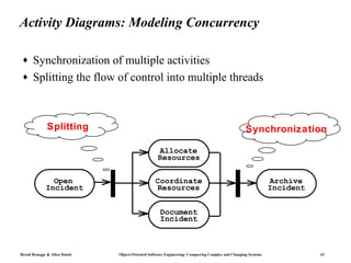
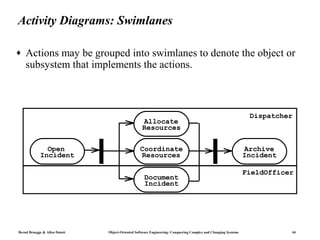
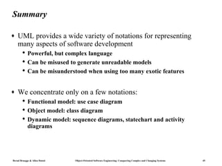

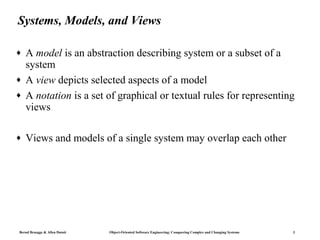
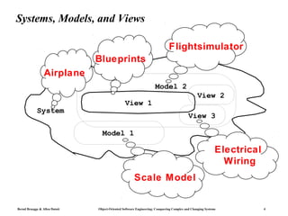
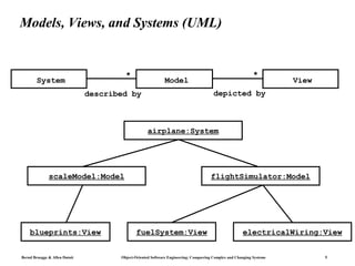
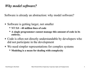
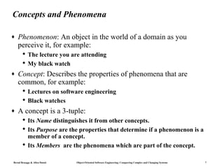
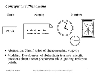
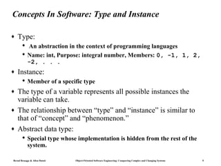
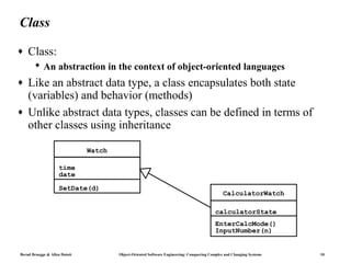
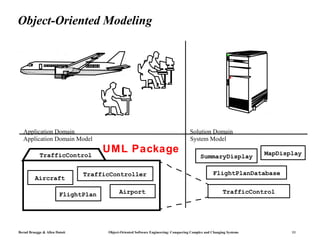
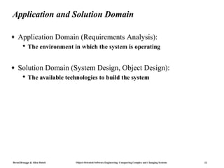
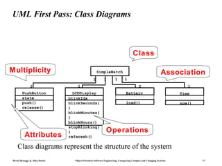
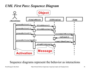
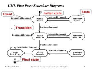
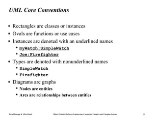
This document discusses object-oriented modeling and the Unified Modeling Language (UML). It introduces key concepts in modeling including systems, models, and views. Models abstract and simplify a system, while views depict selected aspects of a model. The document then discusses why software needs to be modeled, and introduces concepts, types, and classes in software modeling. It describes the relationship between the application domain and solution domain in object-oriented modeling. Finally, it provides an overview of commonly used UML diagrams including use case diagrams, class diagrams, sequence diagrams, statechart diagrams, and activity diagrams.