Download as PDF, PPTX


![Testing Facility: Nuovo Pignone
System Performance
Torque Ripple: 2%
Mod.
20-giu-07 Hybrid
Speed
3000
3000
3000
3000
3000
Load
(MW)
6,5
26
29
32
34
Motor in helper
mode
33KV
33KV
Current Voltage
THD%
THD%
7,5
3,0
2,6
3,0
2,5
3,0
2,5
3,0
2,5
3,0
Motor Torque
Torque
[kNm]
19
82
92
102
108
Ripple%
Mech
7,5
4,5
2,5
2,0
2,0
Grid side Current THD = 2,5%
Grid phase current
Mod.
15-giu-07 Asyn.
Speed
1500
2820
3000
3300
3300
3000
PPT2013.01.01.13EN
www.nidec-asi.com
AFE interleaving off AFE interleaving on
Grid
Grid
Grid
Grid
Load Current Voltage Current Voltage
(MW) THD%
THD%
THD%
THD%
5
26,0
13,0
9,0
3,0
21
7,0
13,0
3,0
3,0
21
7,0
13,0
3,0
3,0
20
6,5
13,0
3,0
3,0
27
5,5
13,0
2,5
3,0
27
5,5
13,0
2,5
3,0
20](https://image.slidesharecdn.com/nidecasisilcovertgn-131208203513-phpapp02/85/Nidec-asi-silcovert-gn-20-320.jpg)


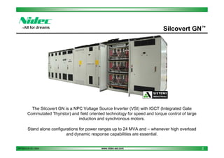
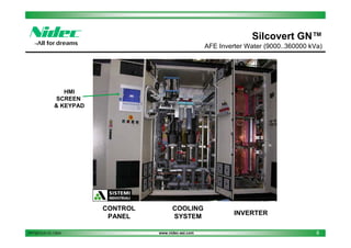
The Silcovert GN is a voltage source inverter using IGCT technology to control large induction and synchronous motors for power ranges up to 24 MVA. It provides high efficiency, power factor, and low harmonic content. A digital control platform provides a user-friendly interface for flexibility in applications. The document provides details on the specifications, components, cooling system, control architecture, HMI, testing facilities, and main applications of the Silcovert GN motor drive.


![Sectionanddevelopment(thedirectdata[1].com)](https://cdn.slidesharecdn.com/ss_thumbnails/sectionanddevelopmentthedirectdata1-170802182625-thumbnail.jpg?width=640&height=640&fit=bounds)


